Basic Design Features of Radiation Facilities
Hazards associated with the handling and use of radiation sources necessitate special features of design and construction that are not required for conventional laboratories or working areas. These special design features are incorporated so that the facility worker is not unduly hampered while ensuring that he or she is not exposed to undue external or internal radiation hazards.
Access to all areas where exposure to radiation sources or radioactive materials could occur must be controlled not only with respect to the facility workers who may be permitted to enter such work areas, but also with respect to the type of clothing or protective equipment that they should wear and the precautions that they should take in controlled areas. In the administration of such control measures, it helps to classify radiation work areas based on the presence of ionizing radiation, on the presence of radioactive contamination or both. The introduction of such work area classification concepts in early planning stages will result in the facility having all the features necessary to make operations with radiation sources less hazardous.
Classification of working areas and laboratory types
The basis for the classification of the work area is the grouping of radionuclides according to their relative radiotoxicities per unit activity. Group I should be classified as very high toxicity radionuclides, Group II as moderate-to-high toxicity radionuclides, Group III as moderate toxicity radionuclides, and Group IV as low toxicity radionuclides. Table 1 shows the toxicity group classification of many radionuclides.
Table 1. Radionuclides classified according to relative radiotoxicity per unit activity
|
Group I: Very high toxicity |
|||||||||
|
210Pb |
210Po |
223Ra |
226Ra |
228Ra |
227Ac |
227Th |
228Th |
230Th |
231Pa |
|
230U |
232U |
233U |
234U |
237Np |
238Pu |
239Pu |
240Pu |
241Pu |
242Pu |
|
241Am |
243Am |
242Cm |
243Cm |
244Cm |
245Cm |
246Cm |
249Cm |
250Cf |
252Cf |
|
Group II: High toxicity |
|||||||||
|
22Na |
36Cl |
45Ca |
46Sc |
54Mn |
56Co |
60Co |
89Sr |
90Sr |
91Y |
|
95Zr |
106Ru |
110Agm |
115Cdm |
114Inm |
124Sb |
125Sb |
127Tem |
129Tem |
124I |
|
126I |
131I |
133I |
134Cs |
137Cs |
140Ba |
144Ce |
152Eu (13 y) |
154Eu |
160Tb |
|
170Tm |
181Hf |
210Bi |
182Ta |
192Ir |
204Tl |
207Bi |
230Pa |
211At |
212Pb |
|
224Ra |
228Ac |
234Th |
236U |
249Bk |
|||||
|
Group III: Moderate toxicity |
|||||||||
|
7Be |
14C |
18F |
24Na |
38Cl |
31Si |
32P |
35S |
41A |
42K |
|
43K |
47Sc |
48Sc |
48V |
51Cr |
52Mn |
56Mn |
52Fe |
55Fe |
59Fe |
|
57Co |
53Ni |
65Ni |
64Cu |
65Zn |
69Znm |
72Ga |
73As |
74As |
76As |
|
77As |
82Br |
85Krm |
87Kr |
86Rb |
85Sr |
91Sr |
90Y |
92Y |
93Y |
|
97Zr |
95Nb |
99Mo |
96Tc |
97Tcm |
97Tc |
99Tc |
97Ru |
103Ru |
105Ru |
|
105Rh |
109Pd |
105Ag |
111Ag |
109Cd |
115Cd |
115Inm |
113Sn |
125Sn |
122Sb |
|
125Tem |
129Te |
131Tem |
132Te |
130I |
132I |
134I |
135I |
135Xe |
131Cs |
|
136Cs |
140La |
141Ce |
143Ce |
142Pr |
143Pr |
147Nd |
149Nd |
147Pm |
149Pm |
|
151Sm |
152Eu (9.2 h) |
155Eu |
153Gd |
159Gd |
165Dy |
166Dy |
166Ho |
169Er |
171Er |
|
171Tm |
177Lu |
181W |
185W |
187W |
183Re |
186Re |
188Re |
185Os |
191Os |
|
193Os |
190Ir |
195Ir |
191Pt |
193Pt |
197Pt |
196Au |
198Au |
199Au |
197Hg |
|
197Hgm |
203Hg |
200Tl |
201Tl |
202Tl |
203Pb |
206Bi |
212Bi |
220Rn |
222Rn |
|
231Th |
233Pa |
239Np |
|||||||
|
Group IV: Low toxicity |
|||||||||
|
3H |
15O |
37A |
58Com |
59Ni |
69Zn |
71Ge |
85Kr |
85Srm |
87Rb |
|
91Ym |
93Zr |
97Nb |
96Tcm |
99Tcm |
103Rhm |
133Inm |
129I |
131Xem |
133Xe |
|
134Csm |
135Cs |
147Sm |
187Re |
191Osm |
193Ptm |
197Ptm |
natTh |
232Th |
235U |
|
238U |
natU |
||||||||
(IAEA 1973)
Three broad types of laboratories can be envisaged on the basis of radiotoxicity considerations, the amounts or quantities of radioactive materials that will be handled in the work area and the type of operations involved.
Table 2 describes laboratories by type and provides examples for each type. Table 3 shows the types of laboratories along with the work area classification and access control (IAEA 1973).
Table 2. Classification of working areas
|
Type |
Definition |
Access control |
Typical operations |
|
1 |
Areas in which the external radiation absorbed dose levels or radioactive contamination levels could be high |
Access controlled to radiation workers only, under strictly controlled working conditions and with appropriate protective equipment |
Hot laboratories, highly contaminated areas |
|
2 |
Areas in which external radiation levels could exist and in which the possibility of contamination necessitates operating instructions |
Access limited to radiation workers with |
Luminizing factories and other equivalent |
|
3 |
Areas in which the average external radiation level is less than 1 mGy·wk-1 and in which the possibility of radioactive contamination necessitates special operating instructions |
Access limited to radiation workers, no |
Working areas in the immediate vicinity of |
|
4 |
Areas within the confines of a radiation facility where the external radiation levels are less than 0.1 mGy•wk-1 and where |
Access uncontrolled |
Administration and patient waiting areas |
(ICRP 1977, IAEA 1973)
Table 3. Classification of laboratories for handling radioactive materials
|
Group of |
Type of laboratory required for the activity specified below |
||
|
Type 1 |
Type 2 |
Type 3 |
|
|
I |
<370 kBq |
70 kBq to |
>37 MBq |
|
II |
<37 MBq |
37 MBq to |
>37 GBq |
|
III |
<37 GBq |
37 GBq to |
>370 GBq |
|
IV |
<370 GBq |
370 GBq to |
>37 Tbq |
|
Operational factors for laboratory use of radioactive material |
Multiplication factors for the activity levels |
|
Simple storage |
×100 |
|
Simple wet operations (for example, preparation of aliquots of stock solution) |
×10 |
|
Normal chemical operations (for example, simple chemical preparation and analysis) |
×1 |
|
Complex wet operations (for example, multiple operations or operations with complex glass ware) |
×0.1 |
|
Simple dry operations (for example, manipulations of powders of volatile radioactive compounds) |
×0.1 |
|
Dry and dusty operations (for example, grinding) |
×0.01 |
(ICRP 1977, IAEA 1973)
The hazards involved in working with radioactive material depend not only on the level of radiotoxicity or chemical toxicity and the activity of the radionuclides, but also on the radioactive material’s physical and chemical form and on the nature and complexity of the operation or procedure being performed.
Location of a radiation facility in a building
When a radiation facility is part of a large building, the following should be kept in mind when deciding on the location of such a facility:
- The radiation facility should be located in a relatively unfrequented part of the building, so that access to the area can be easily controlled.
- The potential for fires should be minimal in the area chosen.
- The location of the radiation facility and the heating and ventilation provided should be such that possibilities for the spread of both surface and airborne radioactive contamination are minimal.
- The location of the radiation facility should be chosen judiciously, so that with a minimum expenditure for shielding, radiation levels can be effectively maintained within established limits in the immediate vicinity.
Planning of radiation facilities
Where a gradation of levels of activity is envisioned, the laboratory should be located so that access to areas where high radiation or radioactive contamination levels exist is gradual; that is, one first enters a non-radiation area, then a low activity area, then a medium activity area and so on.
The need for elaborate control of ventilation in small laboratories can be avoided by the use of hoods or glove boxes for handling unsealed sources of radioactive material. However, the ventilation system should be designed to permit air flow in a direction such that any radioactive material that becomes airborne will flow away from the radiation worker. The air flow should always be from an uncontaminated area toward a contaminated or potentially contaminated area.
For the handling of unsealed sources of low to medium radioactivity, the average air speed through the opening in the hood must be about 0.5 ms–1. For highly radiotoxic or high-level radioactivity, the air velocity through the opening should be raised to an average of 0.6 to
1.0 ms–1. However, excessively high air speeds can draw out radioactive materials from open containers and contaminate the entire hood area.
The placement of the hood in the laboratory is important with respect to cross-drafts. In general, a hood should be located well away from doorways where supply or make-up air must enter. Dual-speed fans will permit operation at a higher air velocity while the hood is in use and a lower velocity when it is closed.
The aim of any ventilating system should be to:
- provide comfortable working conditions
- provide continuous air changes (three to five changes per hour) for the purposes of removing and diluting undesirable air contaminants
- minimize the contamination of other areas of the building and the environment.
In the design of radiation facilities, heavy shielding requirements can be minimized by the adoption of certain simple measures. For example, for radiation therapy, accelerators, neutron generators or panoramic radiation sources, a maze can reduce the need for a heavy lead-lined door. Tapering of the primary protective barrier in areas that are not directly in the useful beam or locating the facility partially or completely underground can significantly reduce the amount of required shielding.
Careful attention must be paid to the proper positioning of viewing windows, underground conduit cables and ventilation system baffles. The viewing window should intercept scattered radiation only. Even better is a closed circuit television, which can also improve efficiency.
Surface finishes within a work area
All raw surfaces, such as plaster, concrete, wood and so on, should be permanently sealed with a suitable material. The choice of material should be made with the following considerations in mind:
- the provision of a smooth, chemically inert surface
- the environmental conditions of temperature, humidity and mechanical wear and tear to which the surfaces may be exposed
- compatibility with radiation fields to which the surface is exposed
- the need for ease of repair in the event of damage.
Ordinary paints, varnishes and lacquers are not recommended for covering wear surfaces. The application of a surfacing material that can be easily removed may be helpful if contamination occurs and decontamination is required. However, the removal of such materials sometimes can be difficult and messy.
Plumbing
Sinks, wash basins and floor drains should be properly marked. Wash basins where contaminated hands may be washed should have knee- or foot-operated faucets. It may be economical to reduce maintenance by using piping which can be easily decontaminated or replaced if required. In some cases it may be advisable to install underground holding or storage tanks to control the disposal of liquid radioactive materials.
Radiation Shielding Design
Shielding is important for reducing radiation exposure of facility workers and members of the general public. Shielding requirements depend on a number of factors, including the time that radiation workers or members of the public are exposed to the radiation sources and the type and energy of the radiation sources and radiation fields.
In the design of radiation shields, the shielding material should be placed near the radiation source if possible. Separate shielding considerations must be made for each type of radiation concerned.
Shielding design can be a complex task. For example, the use of computers to model shielding for accelerators, reactors and other high-level radiation sources is beyond the scope of this article. Qualified experts always should be consulted for complex shielding design.
Gamma source shielding
The attenuation of gamma radiation is qualitatively different from that of either alpha or beta radiation. Both of those types of radiation have a definite range in matter and are completely absorbed. Gamma radiation, on the other hand, can be reduced in intensity by increasingly thicker absorbers but it cannot be completely absorbed. If the attenuation of monoenergetic gamma rays is measured under conditions of good geometry (that is, the radiation is well collimated in a narrow beam) the intensity data, when plotted on a semi-log graph versus absorber thickness, will lie on a straight line with the slope equal to the attenuation
coefficient, μ.
The intensity or absorbed dose rate transmitted through an absorber can be calculated as follows:
I(t) = I(0)e– μ t
where I(t) is the gamma-ray intensity or absorbed dose rate transmitted through an absorber of thickness t.
The units of μ and t are the reciprocal of each other. If the absorber thickness t is measured in cm, then μ is the linear attenuation coefficient and has units of cm–1. If t has units of areal density (g/cm2), then μ is the mass attenuation coefficient μm and has units of cm2/g.
As a first-order approximation using areal density, all materials have about the same photon attenuation properties for photons with energies between about 0.75 and 5.0 MeV (mega-electron volts). Within this energy range, gamma shielding properties are approximately proportional to the density of the shielding material. For lower or higher photon energies, absorbers of higher atomic number provide more effective shielding than those of lower atomic number, for a given areal density.
Under conditions of poor geometry (for example, for a broad beam or for a thick shield), the above equation will significantly underestimate the required shield thickness because it assumes that every photon that interacts with the shield will be removed from the beam and not be detected. A significant number of photons may be scattered by the shield into the detector, or photons that had been scattered out of the beam may be scattered back into it after a second interaction.
A shield thickness for conditions of poor geometry may be estimated through the use of the build-up factor B that may be estimated as follows:
I(t) = I(0)Be– μ t
The build-up factor is always greater than one, and may be defined as the ratio of the intensity of the photon radiation, including both the primary and scattered radiation, at any point in the beam, to the intensity of the primary beam only at that point. The build-up factor may apply either to radiation flux or to absorbed dose rate.
Build-up factors have been calculated for various photon energies and various absorbers. Many of the graphs or tables give the shield thickness in terms of relaxation lengths. A relaxation length is the thickness of a shield that will attenuate a narrow beam to 1/e (about 37%) of its original intensity. One relaxation length, therefore, is numerically equal to the reciprocal of the linear attenuation coefficient (that is, 1/μ).
The thickness of an absorber that, when introduced into the primary photon beam, reduces the absorbed dose rate by one-half is called the half-value layer (HVL) or half-value thickness (HVT). The HVL may be calculated as follows:
HVL = ln2 / μ
The required photon shield thickness can be estimated by assuming narrow-beam or good geometry while calculating the required shielding, and then increasing the value thus found by one HVL to account for build-up.
The thickness of an absorber that, when introduced into the primary photon beam, reduces the absorbed dose rate by one-tenth is the tenth-value layer (TVL). One TVL is equal to about 3.32 HVLs, since:
ln10 / ln2 ≈ 3.32
Values for both TVLs and HVLs have been tabulated for various photon energies and several common shielding materials (e.g., lead, steel and concrete) (Schaeffer 1973).
The intensity or absorbed dose rate for a point source obeys the inverse square law and may be calculated as follows:

where Ii is the photon intensity or absorbed dose rate at distance di from the source.
Medical and non-medical x-ray equipment shielding
Shielding for x-ray equipment is considered under the two categories, source shielding and structural shielding. Source shielding is usually provided by the manufacturer of the x-ray tube housing.
Safety regulations specify one type of protective tube housing for medical diagnostic x-ray facilities and another type for medical therapeutic x-ray facilities. For non-medical x-ray equipment, the tube housing and other parts of the x-ray apparatus, such as the transformer, are shielded to reduce the leakage x-ray radiation to acceptable levels.
All x-ray machines, both medical and non-medical, have protective tube housings designed to limit the amount of leakage radiation. Leakage radiation, as used in these specifications for tube housings, means all radiation coming from the tube housing except for the useful beam.
Structural shielding for an x-ray facility provides protection from the useful or primary x-ray beam, from leakage radiation and from scatter radiation. It encloses both the x-ray equipment and the object being irradiated.
The amount of scatter radiation depends on the x-ray field size, energy of the useful beam, the effective atomic number of the scattering media and the angle between the incoming useful beam and the direction of scatter.
A key design parameter is the facility workload (W):
![]()
where W is the weekly workload, usually given in mA-min per week; E is the tube current multiplied by the exposure time per view, usually given in mA s; Nv is the number of views per patient or object irradiated; Np is the number of patients or objects per week and k is a conversion factor (1 min divided by 60 s).
Another key design parameter is the use factor Un for a wall (or floor or ceiling) n. The wall may be protecting any occupied area such as a control room, office or waiting room. The use factor is given by:
![]()
where, Nv,n is the number of views for which the primary x ray beam is directed toward wall n.
The structural shielding requirements for a given x ray facility are determined by the following:
- the maximum tube potential, in kilovolts-peak (kVp), at which the x ray tube is operated
- the maximum beam current, in mA, at which the x ray system is operated
- the workload (W), which is a measure, in suitable units (usually mA-min per week), of the amount of use of the x ray system
- the use factor (U), which is the fraction of the workload during which the useful beam is pointed in the direction of interest
- the occupancy factor (T), which is the factor by which the workload should be multiplied to correct for the degree or type of occupancy of the area to be protected
- the maximum permissible dose equivalent rate (P) to a person for controlled and non-controlled areas (typical absorbed dose limits are 1 mGy for a controlled area in one week and 0.1 mGy for a non-controlled area in one week)
- type of shielding material (for example, lead or concrete)
- the distance (d) from the source to the location being protected.
With these considerations included, the value of the primary beam ratio or transmission factor K in mGy per mA-min at one metre is given by:
![]()
Shielding of the x-ray facility must be constructed so that protection is not impaired by joints; by openings for ducts, pipes and so on, that pass through the barriers; or by conduits, service boxes and so on, embedded in the barriers. The shielding should cover not only the back of the service boxes, but also the sides, or be extended sufficiently to offer equivalent protection. Conduits that pass through barriers should have sufficient bends to reduce the radiation to the required level. Observation windows must have shielding equivalent to that required for the partition (barrier) or door in which they are located.
Radiation therapy facilities may require door interlocks, warning lights, closed circuit television or means for audible (e.g., voice or buzzer) and visual communication between anyone who may be in the facility and the operator.
Protective barriers are of two types:
- primary protective barriers, which are sufficient to attenuate the primary (useful) beam to the required level
- secondary protective barriers, which are sufficient to attenuate leakage, scattered and stray radiation to the required level.
To design the secondary protective barrier, separately calculate the required thickness to protect against each component. If the required thicknesses are about the same, add an additional HVL to the greatest calculated thickness. If the greatest difference between the calculated thicknesses is one TVL or more, the thickest of the calculated values will suffice.
Scattered radiation intensity depends on scattering angle, energy of the useful beam, field size or scattering area, and subject composition.
When designing secondary protective barriers, the following simplifying conservative assumptions are made:
- When x rays are produced at 500 kV or less, the energy of the scattered radiation is equal to the energy of the useful beam.
- After being scattered, the x-ray energy spectrum for beams generated at voltages greater than 500 kV are degraded to that of a 500 kV beam, and the absorbed dose rate at 1 m and 90 degrees from the scatterer is 0.1% of that in the useful beam at the point of scattering.
The transmission relationship for scattered radiation is written in terms of the scattering transmission factor (Kμx) with units of mGy•m2 (mA-min)–1:
![]()
where P is the maximum weekly absorbed dose rate (in mGy), dscat is the distance from the x ray tube’s target and the object (patient), dsec is the distance from the scatterer (object) to the point of interest that the secondary barriers are meant to shield, a is the ratio of scattered radiation to incident radiation, f is the actual scattering field size (in cm2), and F is a factor accounting for the fact that x ray output increases with voltage. Smaller values of Kμx require thicker shields.
The leakage attenuation factor BLX for diagnostic x-ray systems is calculated as follows:
![]()
where d is the distance from the tube target to the point of interest and I is the tube current in mA.
The barrier attenuation relationship for therapeutic x-ray systems operating at 500 kV or less is given by:
![]()
For therapeutic x-ray tubes operating at potentials greater than 500 kV, the leakage is usually limited to 0.1% of the intensity of the useful beam at 1 m. The attenuation factor in this case is:
![]()
where Xn is the absorbed dose rate (in mGy/h) at 1 m from a therapeutic x-ray tube operated at a tube current of 1 mA.
The number n of HVLs required to obtain the desired attenuation BLX is obtained from the relationship:
![]()
or
![]()
Beta particle shielding
Two factors must be considered when designing a shield for a high-energy beta emitter. They are the beta particles themselves and the bremsstrahlung produced by beta particles absorbed in the source and in the shield. Bremsstrahlung consists of x-ray photons produced when high-speed charged particles undergo rapid deceleration.
Therefore, a beta shield often consists of a substance of low atomic number (to minimize bremsstrahlung production) that is thick enough to stop all the beta particles. This is followed by a material of high atomic number that is thick enough to attenuate bremsstrahlung to an acceptable level. (Reversing the order of the shields increases bremsstrahlung production in the first shield to a level so high that the second shield may provide inadequate protection.)
For purposes of estimating bremsstrahlung hazard, the following relationship may be used:
![]()
where f is the fraction of the incident beta energy converted into photons, Z is the atomic number of the absorber, and Eβ is the maximum energy of the beta particle spectrum in MeV. To assure adequate protection, it is normally assumed that all bremsstrahlung photons are of the maximum energy.
The bremsstrahlung flux F at a distance d from the beta source can be estimated as follows:
![]()
`Eβ is the average beta particle energy and can be estimated by:
![]()
The range Rβ of beta particles in units of areal density (mg/cm2) may be estimated as follows for beta particles with energies between 0.01 and 2.5 MeV:
![]()
where Rβ is in mg/cm2 and Eβ is in MeV.
For Eβ>2.5 MeV, the beta particle range Rβ may be estimated as follows:
![]()
where Rβ is in mg/cm2 and Eβ is in MeV.
Alpha particle shielding
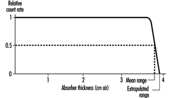
Alpha particles are the least penetrating type of ionizing radiation. Because of the random nature of its interactions, the range of an individual alpha particle varies between nominal values as indicated in figure 1. Range in the case of alpha particles may be expressed in different ways: by minimum, mean, extrapolated, or maximum range. The mean range is the most accurately determinable, corresponds to the range of the “average” alpha particle, and is used most often.
Figure 1. Typical range distribution of alpha particles
Air is the most commonly used absorbing medium for specifying the range-energy relationship of alpha particles. For alpha energy Eα less than about 4 MeV, Rα in air is approximately given by:
![]()
where Rα is in cm, Eα in MeV.
For Eα between 4 and 8 MeV, Rα in air is given approximately by:
![]()
where Rα is in cm, Eα in MeV.
The range of alpha particles in any other medium may be estimated from the following relationship:
Rα (in other medium; mg/cm2) » 0.56 A1/3 Rα (in air; cm) where A is the atomic number of the medium.
Neutron shielding
As a general rule of thumb for neutron shielding, neutron energy equilibrium is achieved and then remains constant after one or two relaxation lengths of shielding material. Therefore, for shields thicker than a few relaxation lengths, the dose equivalent outside concrete or iron shielding will be attenuated with relaxation lengths of 120 g/cm2 or 145 g/cm2, respectively.
Neutron energy loss by elastic scattering requires a hydrogenous shield to maximize the energy transfer as the neutrons are moderated or slowed down. For neutron energies above 10 MeV, inelastic processes are effective in attenuating neutrons.
As with nuclear power reactors, high-energy accelerators require heavy shielding to protect workers. Most of the dose equivalents to workers come from exposure to activated radioactive material during maintenance operations. Activation products are produced in the accelerator’s components and support systems.
Monitoring of the Workplace Environment
It is necessary to deal separately with the design of routine and of operational monitoring programs for the workplace environment. Special monitoring programs will be designed to achieve specific objectives. It is not desirable to design programs in general terms.
Routine monitoring for external radiation
An important part in the preparation of a program for routine monitoring for external radiation in the workplace is to conduct a comprehensive survey when a new radiation source or a new facility is put into service, or when any substantial changes have been made or may have been made in an existing installation.
The frequency of routine monitoring is determined by consideration of the expected changes in the radiation environment. If changes to the protective equipment or alterations of the processes conducted in the workplace are minimal or non-substantial, then routine radiation monitoring of the workplace is rarely required for review purposes. If the radiation fields are subject to increase rapidly and unpredictably to potentially hazardous levels, then an area radiation monitoring and warning system is required.
Operational monitoring for external radiation
The design of an operational monitoring program depends greatly on whether the operations to be conducted influence the radiation fields or whether the radiation fields will remain substantially constant throughout normal operations. The detailed design of such a survey depends critically on the form of the operation and on the conditions under which it takes place.
Routine monitoring for surface contamination
The conventional method of routine monitoring for surface contamination is to monitor a representative fraction of the surfaces in an area at a frequency dictated by experience. If operations are such that considerable surface contamination is likely and such that workers could carry significant amounts of radioactive material out of the work area in a single event, routine monitoring should be supplemented by the use of portal contamination monitors.
Operational monitoring for surface contamination
One form of operational monitoring is the surveying of items for contamination when they leave a radiologically controlled area. This monitoring must include workers’ hands and feet.
The principle objectives of a program of monitoring for surface contamination are:
- to assist in preventing the spread of radioactive contamination
- to detect failures of containment or departures from good operating procedures
- to limit surface contamination to levels at which general standards of good housekeeping are adequate to keep radiation exposures as low as reasonably achievable and to avoid excessive exposures caused by contamination of clothing and skin
- to provide information for the planning of optimized programs for individuals, for air monitoring and for defining operational procedures.
Monitoring for airborne contamination
The monitoring of airborne radioactive materials is important because inhalation is usually the most important route of intake of such material by radiation workers.
The monitoring of the workplace for airborne contamination will be needed on a routine basis in the following circumstances:
- when gaseous or volatile materials are handled in quantity
- when the handling of any radioactive material in such operations results in frequent and substantial contamination of the workplace
- during the processing of moderately to highly toxic radioactive materials
- during the handling of unsealed therapeutic radionuclides in hospitals
- during the use of hot cells, reactors and critical assemblies.
When an air monitoring program is required, it must:
- be able to assess the probable upper limit of the inhalation of radioactive material by radiation workers
- be able to draw attention to unexpected airborne contamination so that radiation workers can be protected and remedial measures instituted
- provide information for planning of programs of individual monitoring for internal contamination.
The most common form of monitoring for airborne contamination is the use of air samplers at a number of selected locations selected to be reasonably representative of the breathing zones of radiation workers. It may be necessary to make samples more accurately represent breathing zones by using personal air or lapel samplers.
Detection and measurement of radiation and radioactive contamination
The monitoring or surveying by wipes and instrument surveys of bench tops, floors, clothing, skin, and other surfaces are at best qualitative procedures. It is difficult to make them highly quantitative. The instruments used are usually detecting types rather than measuring devices. Since the amount of radioactivity involved is often small, the sensitivity of the instruments should be high.
The requirement for portability of contamination detectors depends on their intended uses. If the instrument is for general-purpose monitoring of laboratory surfaces, a portable type of instrument is desirable. If the instrument is for a specific use in which the item to be monitored can be brought to the instrument, then portability is not necessary. Clothing monitors and hand and shoe monitors generally are not portable.
Count-rate instruments and monitors usually incorporate meter readouts and aural outputs or earphone jacks. Table 4 identifies instruments that may be used for the detection of radioactive contamination.+
Table 4. Contamination detection instruments
|
Instrument |
Counting rate range and other characteristics1 |
Typical uses |
Remarks |
|
bg surface monitors2 |
|||
|
General |
|||
|
Portable count rate meter (thin-walled or thin window G-M3 counter) |
0-1,000 cpm |
Surfaces, hands, clothing |
Simple, reliable, battery-powered |
|
Thin end-window |
0-1,000 cpm |
Surfaces, hands, clothing |
Line-operated |
|
Personnel |
|||
|
Hand-and-shoe monitor, G-M or |
Between 1½ and 2 times natural |
Rapid monitoring for contamination |
Automatic operation |
|
Special |
|||
|
Laundry monitors, floor monitors, |
Between 1½ and 2 times natural |
Monitoring for contamination |
Convenient and rapid |
|
Alpha surface monitors |
|||
|
General |
|||
|
Portable air proportional counter with probe |
0-100,000 cpm over 100 cm2 |
Surfaces, hands, clothing |
Not for use in high humidity, battery- |
|
Portable gas-flow counter with probe |
0-100,000 cpm over 100 cm2 |
Surfaces, hands, clothing |
Battery-powered, fragile window |
|
Portable scintillation counter with probe |
0-100,000 cpm over 100 cm2 |
Surfaces, hands, clothing |
Battery-powered, fragile window |
|
Personal |
|||
|
Hand-and-shoe proportional counter-type, monitor |
0-2,000 cpm over about 300 cm2 |
Rapid monitoring of hands and shoes for contamination |
Automatic operation |
|
Hand-and-shoe scintillation counter-type, monitor |
0-4,000 cpm over about 300 cm2 |
Rapid monitoring of hands and shoes for contamination |
Rugged |
|
Wound monitors |
Low-energy photon detection |
Plutonium monitoring |
Special design |
|
Air monitors |
|||
|
Particle samplers |
|||
|
Filter paper, high-volume |
1.1 m3/min |
Quick grab samples |
Intermittent use, requires separate |
|
Filter paper, low volume |
0.2-20 m3/h |
Continuous room air monitoring |
Continuous use, requires separate |
|
Lapel |
0.03 m3/min |
Continuous breathing zone air monitoring |
Continuous use, requires separate |
|
Electrostatic precipitator |
0.09 m3/min |
Continuous monitoring |
Sample deposited on cylindrical shell, |
|
Impinger |
0.6-1.1 m3/min |
Alpha contamination |
Special uses, requires separate counter |
|
Tritium air monitors |
|||
|
Flow ionization chambers |
0-370 kBq/m3 min |
Continuous monitoring |
May be sensitive to other ionization |
|
Complete air monitoring systems |
Minimum detectable activity |
|
|
|
Fixed filter paper |
α » 0.04 Bq/m3; βγ » 0.04 Bq/m3 |
Background buildup can mask low-level activity, counter included |
|
|
Moving filter paper |
α » 0.04 Bq/m3; βγ » 0.04 Bq/m3 |
Continuous record of air activity, time of measurement can be adjusted from |
|
1 cpm = counts per minute.
2 Few surface monitors are suitable for detecting tritium (3H). Wipe tests counted by liquid scintillation devices are appropriate for detecting tritium contamination.
3 G-M = Geiger-Muller countrate meter.
Alpha contamination detectors
The sensitivity of an alpha detector is determined by its window area and window thickness. Generally window area is 50 cm2 or greater with a window areal density of 1 mg/cm2 or less. Alpha contamination monitors should be insensitive to beta and gamma radiation in order to minimize background interference. This is generally accomplished by pulse height discrimination in the counting circuit.
Portable alpha monitors can be either gas proportional counters or zinc sulphide scintillation counters.
Beta contamination detectors
Portable beta monitors of several types can be used for the detection of beta-particle contamination. Geiger-Mueller (G-M) count-rate meters generally require a thin window (areal density between 1 and 40 mg/cm2). Scintillation (anthracene or plastic) counters are very sensitive to beta particles and relatively insensitive to photons. Portable beta counters generally cannot be used to monitor for tritium (3H) contamination because tritium beta-particle energy is very low.
All instruments used for beta contamination monitoring also respond to background radiation. This must be taken into account when interpreting instrument readings.
When high background radiation levels exist, portable counters for contamination monitoring are of limited value, since they do not indicate small increases in initially high counting rates. Under these conditions smears or wipe tests are recommended.
Gamma contamination detectors
Since most gamma emitters also emit beta particles, most contamination monitors will detect both beta and gamma radiation. The usual practice is to use a detector that is sensitive to both types of radiation in order to have increased sensitivity, since the detection efficiency is usually greater for beta particles than for gamma rays. Plastic scintillators or sodium iodide (NaI) crystals are more sensitive to photons than are G-M counters, and are therefore recommended for detecting gamma rays.
Air samplers and monitors
Particulates may be sampled by the following methods: sedimentation, filtration, impaction and electrostatic or thermal precipitation. However, particulate contamination in the air is generally monitored by filtration (pumping air through filter media and measuring the radioactivity on the filter). Sampling flow rates generally are greater than 0.03 m3/min. However, most laboratories’ sampling flow rates are no more than 0.3 m3/min. Specific types of air samplers include “grab” samplers and continuous air monitors (CAM). The CAMs are available with either fixed or moving filter paper. A CAM should include an alarm since its principle function is to warn of changes in airborne contamination.
Because alpha particles have very short range, surface-loading filters (for example, membrane filters) must be used for the measurement of alpha-particle contamination. The sample collected must be thin. The time between collection and measurement must be considered to allow for the decay of radon (Rn) progeny.
Radioiodines such as 123I, 125I and 131I can be detected with filter paper (particularly if the paper is loaded with charcoal or silver nitrate) because some of the iodine will deposit on the filter paper. However, quantitative measurements require activated charcoal or silver zeolite traps or canisters to provide efficient absorption.
Tritiated water and tritium gas are the primary forms of tritium contamination. Although tritiated water has some affinity for most filter papers, filter paper techniques are not very effective for tritiated water sampling. The most sensitive and accurate measurement methods involve the absorption of tritiated water vapour condensate. Tritium in the air (for example, as hydrogen, hydrocarbons or water vapour) can be measured effectively with Kanne chambers (flow-through ionization chambers). Absorption of tritiated water vapour from an air sample can be accomplished by passing the sample through a trap containing a silica-gel molecular sieve or by bubbling the sample through distilled water.
Depending on the operation or process it may be necessary to monitor for radioactive gases. This can be accomplished with Kanne chambers. The most commonly used devices for sampling by absorption are fretted gas scrubbers and impingers. Many gases may also be collected by cooling the air below the freezing point of the gas and collecting the condensate. This method of collection is most often used for tritium oxide and noble gases.
There are a number of ways to obtain grab samples. The method selected should be appropriate for the gas to be sampled and the required method of analysis or measurement.
Monitoring of effluent
Effluent monitoring refers to the measurement of radioactivity at its point of release to the environment. It is relatively easy to accomplish because of the controlled nature of the sampling location, which is usually in a waste stream that is being discharged through a stack or liquid discharge line.
Continuous monitoring of airborne radioactivity may be necessary. In addition to the sample collection device, usually a filter, a typical sampling arrangement for particulates in air includes an air-moving device, a flowmeter and associated ducting. The air-moving device is located downstream from the sample collector; that is, the air is first passed through the sample collector, then through the remainder of the sampling system. Sampling lines, particularly those ahead of the sample collector system, should be kept as short as possible and free of sharp bends, areas of turbulence, or resistance to the air flow. Constant volume over a suitable range of pressure drops should be used for air sampling. Continuous sampling for radioactive xenon (Xe) or krypton (Kr) isotopes is accomplished by adsorption on activated charcoal or by cryogenic means. The Lucas cell is one of the oldest techniques and still the most popular method for the measurement of Rn concentrations.
Continuous monitoring of liquids and waste lines for radioactive materials is sometimes necessary. Waste lines from hot laboratories, nuclear medicine laboratories and reactor coolant lines are examples. Continuous monitoring can be performed, however, by routine laboratory analysis of a small sample proportional to the effluent flow rate. Samplers that take periodic aliquots or that continuously extract a small amount of liquid are available.
Grab sampling is the usual method used to determine the concentration of radioactive material in a hold-up tank. The sample must be taken after recirculation in order to compare the result of the measurement with allowable discharge rates.
Ideally, results of effluent monitoring and environmental monitoring will be in good agreement, with the latter calculable from the former with the aid of various pathway models. However, it must be recognized and emphasized that effluent monitoring, no matter how good or extensive, cannot substitute for actual measurement of radiological conditions in the environment.