All materials differ in the degree to which electric charges can pass through them. Conductors allow charges to flow, while insulators hinder the motion of charges. Electrostatics is the field devoted to studying charges, or charged bodies at rest. Static electricity results when electric charges which do not move are built up on objects. If the charges flow, then a current results and the electricity is no longer static. The current that results from moving charges is commonly referred to by laypeople as electricity, and is discussed in the other articles in this chapter. Static electrification is the term used to designate any process resulting in the separation of positive and negative electrical charges. Conduction is measured with a property called conductance, while an insulator is characterized by its resistivity. Charge separation which leads to electrification can occur as the result of mechanical processes—for example, contact between objects and friction, or the collision of two surfaces. The surfaces can be two solids or a solid and a liquid. The mechanical process can, less commonly, be the rupture or separation of solid or liquid surfaces. This article focuses on contact and friction.
Electrification Processes
The phenomenon of generation of static electricity by friction (triboelectrification) has been known for thousands of years. Contact between two materials is sufficient to induce electrification. Friction is simply a type of interaction which increases the area of contact and generates heat—friction is the general term to describe the movement of two objects in contact; the pressure exerted, its shear velocity and the heat generated are the prime determinants of the charge generated by friction. Sometimes friction will lead to the tearing away of solid particles as well.
When the two solids in contact are metals (metal-metal contact), electrons migrate from one to the other. Every metal is characterized by a different initial potential (Fermi potential), and nature always moves towards equilibrium—that is, natural phenomena work to eliminate the differences in potential. This migration of electrons results in the generation of a contact potential. Because the charges in a metal are very mobile (metals are excellent conductors), the charges will even recombine at the last point of contact before the two metals are separated. It is therefore impossible to induce electrification by bringing together two metals and then separating them; the charges will always flow to eliminate the potential difference.
When a metal and an insulator come into nearly friction-free contact in a vacuum, the energy level of electrons in the metal approaches that of the insulator. Surface or bulk impurities cause this to occur and also prevent arcing (the discharge of electricity between the two charged bodies—the electrodes) upon separation. The charge transferred to the insulator is proportional to the electron affinity of the metal, and every insulator also has an electron affinity, or attraction for electrons, associated with it. Thus, transfer of positive or negative ions from the insulator to the metal is also possible. The charge on the surface following contact and separation is described by equation 1 in table 1.
Table 1. Basic relationships in electrostatics - Collection of equations
Equation 1: Charging by contact of a metal and an insulator
In general, the surface charge density (![]() ) following contact and separation
) following contact and separation
can be expressed by:
![]()
where
e is the charge of an electron
NE is the energy state density at the insulator’s surface
fi is the electron affinity of the insulator, and
fm is the electron affinity of the metal
Equation 2: Charging following contact between two insulators
The following general form of equation 1 applies to the charge transfer
between two insulators with different energy states (perfectly clean surfaces only):
![]()
where NE1 and NE2 are the energy state densities at the surface of the two insulators,
and Ø1 and Ø 2 are the electron affinities of the two insulators.
Equation 3: Maximum surface charge density
The dielectric strength (EG) of the surrounding gas imposes an upper limit on the charge it is
possible to generate on a flat insulating surface. In air, EG is approximately 3 MV/m.
The maximum surface charge density is given by:
![]()
Equation 4: Maximum charge on a spherical particle
When nominally spherical particles are charged by the corona effect, the maximum
charge which each particle can acquire is given by Pauthenier’s limit:
![]()
where
qmax is the maximum charge
a is the particle radius
eI is the relative permittivity and
![]()
Equation 5: Discharges from conductors
The potential of an insulated conductor carrying charge Q is given by V = Q/C and
the stored energy by:
![]()
Equation 6: Time course of potential of charged conductor
In a conductor charged by a constant current (IG), the time course of the
potential is described by:
![]()
where Rf is the conductor’s leak resistance
Equation 7: Final potential of charged conductor
For long time course, t >Rf C, this reduces to:
![]()
and the stored energy is given by:
Equation 8: Stored energy of charged conductor
![]()
When two insulators come into contact, charge transfer occurs because of the different states of their surface energy (equation 2, table 1). Charges transferred to the surface of an insulator can migrate deeper within the material. Humidity and surface contamination can greatly modify the behaviour of charges. Surface humidity in particular increases surface energy state densities by increasing surface conduction, which favours charge recombination, and facilitates ionic mobility. Most people will recognize this from their daily life experiences by the fact that they tend to be subjected to static electricity during dry conditions. The water content of some polymers (plastics) will change as they are being charged. The increase or decrease in water content may even reverse the direction of the charge flow (its polarity).
The polarity (relative positivity and negativity) of two insulators in contact with each other depends on each material’s electron affinity. Insulators can be ranked by their electron affinities, and some illustrative values are listed in table 2. The electron affinity of an insulator is an important consideration for prevention programmes, which are discussed later in this article.
Table 2. Electron affinities of selected polymers*
|
Charge |
Material |
Electron affinity (EV) |
|
– |
PVC (polyvinyl chloride) |
4.85 |
|
Polyamide |
4.36 |
|
|
Polycarbonate |
4.26 |
|
|
PTFE (polytetrafluoroethylene) |
4.26 |
|
|
PETP (polyethylene terephthalate) |
4.25 |
|
|
Polystyrene |
4.22 |
|
|
+ |
Polyamide |
4.08 |
* A material acquires a positive charge when it comes into contact with a material listed above it, and a negative charge when it comes into contact with a material listed below it. The electron affinity of an insulator is multifactorial, however.
Although there have been attempts to establish a triboelectric series which would rank materials so that those which acquire a positive charge upon contact with materials would appear higher in the series than those that acquire a negative charge upon contact, no universally recognized series has been established.
When a solid and a liquid meet (to form a solid-liquid interface), charge transfer occurs due to the migration of ions that are present in the liquid. These ions arise from the dissociation of impurities which may be present or by electrochemical oxidation-reduction reactions. Since, in practice, perfectly pure liquids do not exist, there will always be at least some positive and negative ions in the liquid available to bind to the liquid-solid interface. There are many types of mechanisms by which this binding may occur (e.g., electrostatic adherence to metal surfaces, chemical absorption, electrolytic injection, dissociation of polar groups and, if the vessel wall is insulating, liquid-solid reactions.)
Since substances which dissolve (dissociate) are electrically neutral to begin with, they will generate equal numbers of positive and negative charges. Electrification occurs only if either the positive or the negative charges preferentially adhere to the solid’s surface. If this occurs, a very compact layer, known as the Helmholtz layer is formed. Because the Helmholtz layer is charged, it will attract ions of the opposite polarity to it. These ions will cluster into a more diffuse layer, known as the Gouy layer, which rests on top of the surface of the compact Helmholtz layer. The thickness of the Gouy layer increases with the resistivity of the liquid. Conducting liquids form very thin Gouy layers.
This double layer will separate if the liquid flows, with the Helmholtz layer remaining bound to the interface and the Gouy layer becoming entrained by the flowing liquid. The movement of these charged layers produces a difference in potential (the zeta potential), and the current induced by the moving charges is known as the streaming current. The amount of charge that accumulates in the liquid depends on the rate at which the ions diffuse towards the interface and on the liquid’s resistivity (r). The streaming current is, however, constant over time.
Neither highly insulating nor conducting liquids will become charged—the first because very few ions are present, and the second because in liquids which conduct electricity very well, the ions will recombine very rapidly. In practice, electrification occurs only in liquids with resistivity greater than 107Ωm or less than 1011Ωm, with the highest values observed for r 109 to 1011 Ωm.
Flowing liquids will induce charge accumulation in insulating surfaces over which they flow. The extent to which the surface charge density will build up is limited by (1) how quickly the ions in the liquid recombine at the liquid-solid interface, (2) how quickly the ions in the liquid are conducted through the insulator, or (3) whether surface or bulk arcing through the insulator occurs and the charge is thus discharged. Turbulent flow and flow over rough surfaces favour electrification.
When a high voltage—say several kilovolts—is applied to a charged body (an electrode) which has a small radius (e.g., a wire), the electrical field in the immediate vicinity of the charged body is high, but it decreases rapidly with distance. If there is a discharge of the stored charges, the discharge will be limited to the region in which the electrical field is stronger than the dielectric strength of the surrounding atmosphere, a phenomenon known as the corona effect, because the arcing also emits light. (People may actually have seen small sparks formed when they have personally experienced a shock from static electricity.)
The charge density on an insulating surface can also be changed by the moving electrons that are generated by a high-intensity electrical field. These electrons will generate ions from any gas molecules in the atmosphere with which they come into contact. When the electric charge on the body is positive, the charged body will repel any positive ions which have been created. Electrons created by negatively charged objects will lose energy as they recede from the electrode, and they will attach themselves to gas molecules in the atmosphere, thus forming negative ions which continue to recede away from the charge points. These positive and negative ions can come to rest on any insulating surface and will modify the surface’s charge density. This type of charge is much easier to control and more uniform than the charges created by friction. There are limits to the extent of the charges it is possible to generate in this way. The limit is described mathematically in equation 3 in table 1.
To generate higher charges, the dielectric strength of the environment must be increased, either by creating a vacuum or by metallizing the other surface of the insulating film. The latter stratagem draws the electrical field into the insulator and consequently reduces the field strength in the surrounding gas.
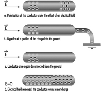
When a conductor in an electrical field (E) is grounded (see figure 1), charges can be produced by induction. Under these conditions, the electrical field induces polarization—the separation of the centres of gravity of the negative and positive ions of the conductor. A conductor temporarily grounded at only one point will carry a net charge when disconnected from the ground, due to the migration of charges in the vicinity of the point. This explains why conducting particles located in a uniform field oscillate between electrodes, charging and discharging at each contact.
Figure 1. Mechanism of charging a conductor by induction
Hazards Associated with Static Electricity
The ill effects caused by the accumulation of static electricity range from the discomfort one experiences when touching a charged object, such as a door handle, to the very serious injuries, even fatalities, which can occur from an explosion induced by static electricity. The physiological effect of electrostatic discharges on humans ranges from uncomfortable prickling to violent reflex actions. These effects are produced by the discharge current and, especially, by the current density on the skin.
In this article we will describe some practical ways in which surfaces and objects can become charged (electrification). When the electrical field induced exceeds the ability of the surrounding environment to withstand the charge (that is, exceeds the dielectric strength of the environment), a discharge occurs. (In air, the dielectric strength is described by Paschen’s curve and is a function of the product of the pressure and the distance between the charged bodies.)
Disruptive discharges can take the following forms:
- sparks or arcs which bridge two charged bodies (two metal electrodes)
- partial, or brush, discharges which bridge a metal electrode and an insulator, or even two insulators; these discharges are termed partial because the conducting path does not totally short-circuit two metal electrodes, but is usually multiple and brushlike
- corona discharges, also known as point effects, which arise in the strong electric field around small-radius charged bodies or electrodes.
Insulated conductors have a net capacitance C relative to ground. This relationship between charge and potential is expressed in equation 5 in table 1.
A person wearing insulating shoes is a common example of an insulated conductor. The human body is an electrostatic conductor, with a typical capacitance relative to ground of approximately 150 pF and a potential of up to 30 kV. Because people can be insulating conductors, they can experience electrostatic discharges, such as the more or less painful sensation sometimes produced when a hand approaches a door handle or other metal object. When the potential reaches approximately 2 kV, the equivalent to an energy of 0.3 mJ will be experienced, although this threshold varies from person to person. Stronger discharges may cause uncontrollable movements resulting in falls. In the case of workers using tools, the involuntary reflex motions may lead to injuries to the victim and others who may be working nearby. Equations 6 to 8 in table 1 describe the time course of the potential.
Actual arcing will occur when the strength of the induced electrical field exceeds the dielectric strength of air. Because of the rapid migration of charges in conductors, essentially all the charges flow to the discharge point, releasing all the stored energy into a spark. This can have serious implications when working with flammable or explosive substances or in flammable conditions.
The approach of a grounded electrode to a charged insulating surface modifies the electric field and induces a charge in the electrode. As the surfaces approach each other, the field strength increases, eventually leading to a partial discharge from the charged insulated surface. Because charges on insulating surfaces are not very mobile, only a small proportion of the surface participates in the discharge, and the energy released by this type of discharge is therefore much lower than in arcs.
The charge and transferred energy appear to be directly proportional to the diameter of the metal electrode, up to approximately 20 mm. The initial polarity of the insulator also influences charge and transferred energy. Partial discharges from positively charged surfaces are less energetic than those from negatively charged ones. It is impossible to determine, a priori, the energy transferred by a discharge from an insulating surface, in contrast to the situation involving conducting surfaces. In fact, because the insulating surface is not equipotential, it is not even possible to define the capacitances involved.
Creeping Discharge
We saw in equation 3 (table 1) that the surface charge density of an insulating surface in air cannot exceed 2,660 pC/cm2.
If we consider an insulating plate or a film of thickness a, resting on a metal electrode or having one metal face, it is easy to demonstrate that the electrical field is drawn into the insulator by the induced charge on the electrode as charges are deposited on the non-metallic face. As a result, the electric field in the air is very weak, and lower than it would be if one of the faces were not metal. In this case, the dielectric strength of air does not limit charge accumulation on the insulating surface, and it is possible to reach very high surface charge densities (>2,660 pC/cm2). This charge accumulation increases the surface conductivity of the insulator.
When an electrode approaches an insulating surface, a creeping discharge involving a large proportion of the charged surface which has become conducting occurs. Because of the large surface areas involved, this type of discharge releases large amounts of energy. In the case of films, the air field is very weak, and the distance between the electrode and the film must be no more than the film thickness for a discharge to occur. A creeping discharge may also occur when a charged insulator is separated from its metallic undercoating. Under these circumstances, the air field increases abruptly and the entire surface of the insulator discharges to re-establish equilibrium.
Electrostatic Discharges and Fire and Explosion Hazards
In explosive atmospheres, violent exothermic oxidation reactions, involving energy transfer to the atmosphere, may be triggered by:
- open flames
- electric sparks
- radio-frequency sparks near a strong radio source
- sparks produced by collisions (e.g., between metal and concrete)
- electrostatic discharges.
We are interested here only in the last case. The flash points (the temperature at which liquid vapours ignite on contact with a naked flame) of various liquids, and the auto-ignition temperature of various vapours are given in the Chemical Section of this Encyclopaedia. The fire hazard associated with electrostatic discharges can be assessed by reference to the lower flammability limit of gases, vapours and solid or liquid aerosols. This limit may vary considerably, as table 3 illustrates.
Table 3. Typical lower flammability limits
|
Discharge |
Limit |
|
Some powders |
Several joules |
|
Very fine sulphur and aluminium aerosols |
Several millijoules |
|
Vapours of hydrocarbons and other organic liquids |
200 microjoules |
|
Hydrogen and acetylene |
20 microjoules |
|
Explosives |
1 microjoule |
A mixture of air and a flammable gas or vapour can explode only when the concentration of the flammable substance is between its upper and lower explosive limits. Within this range, the minimal ignition energy (MIE)—the energy which an electrostatic discharge must possess to ignite the mixture—is highly concentration dependent. The minimal ignition energy has been consistently shown to depend on the speed of energy release and, by extension, on discharge duration. Electrode radius is also a factor:
- Small-diameter electrodes (of the order of several millimetres) result in corona discharges rather than sparks.
- With larger-diameter electrodes (of the order of several centimetres), the electrode mass serves to cool the sparks.
In general, the lowest MIEs are obtained with electrodes that are just big enough to prevent corona discharges.
The MIE also depends on the interelectrode distance, and is lowest at the quenching distance (“distance de pincement”), the distance at which the energy produced in the reaction zone exceeds the thermal losses at the electrodes. It has been experimentally demonstrated that each flammable substance has a maximum safe distance, corresponding to the minimum interelectrode distance at which an explosion can occur. For hydrocarbons, this is less than 1 mm.
The probability of powder explosions is concentration dependent, with the highest probability associated with concentrations of the order of 200 to 500 g/m3. The MIE is also dependent on particle size, with finer powders exploding more easily. For both gases and aerosols, the MIE decreases with temperature.
Industrial Examples
Many processes routinely used for handling and transporting chemicals generate electrostatic charges. These include:
- pouring powders from sacks
- screening
- transport in pipework
- liquid agitation, especially in the presence of multiple phases, suspended solids or droplets of non-miscible liquids
- liquid spraying or misting.
The consequences of electrostatic charge generation include mechanical problems, an electrostatic discharge hazard for operators and, if products containing inflammable solvents or vapours are used, even explosion (see table 4).
Table 4. Specific charge associated with selected industrial operations
|
Operation |
Specific charge |
|
Screening |
10-8 –10-11 |
|
Silo filling or emptying |
10-7 –10-9 |
|
Transport by worm conveyor |
10-6 –10-8 |
|
Grinding |
10-6 –10-7 |
|
Micronization |
10-4 –10-7 |
|
Pneumatic transport |
10-4 –10-6 |
Liquid hydrocarbons, such as oil, kerosene and many common solvents, have two characteristics which render them particularly sensitive to problems of static electricity:
- high resistivity, which allows them to accumulate high levels of charges
- flammable vapours, which increase the risk of low-energy discharges triggering fires and explosions.
Charges may be generated during transport flow (e.g., through pipework, pumps or valves). Passage through fine filters, such as those used during the filling of aeroplane tanks, may result in the generation of charge densities of several hundred microcoulombs per cubic metre. Particle sedimentation and the generation of charged mists or foams during flow-filling of tanks may also generate charges.
Between 1953 and 1971, static electricity was responsible for 35 fires and explosions during or following the filling of kerosene tanks, and even more accidents occurred during the filling of truck tanks. The presence of filters or splashing during filling (due to the generation of foams or mists) were the most commonly identified risk factors. Accidents have also occurred on board oil tankers, especially during tank cleaning.
Principles of Static Electricity Prevention
All problems related to static electricity derive from the:
- generation of electric charges
- accumulation of these charges on insulators or insulated conductors
- electric field produced by these charges, which in turn results in a force or a disruptive discharge.
Preventive measures seek to avoid the accumulation of electrostatic charges, and the strategy of choice is to avoid generating the electric charges in the first place. If this is not possible, measures designed to ground the charges should be implemented. Finally, if discharges are unavoidable, sensitive objects should be protected from the effects of the discharges.
Suppression or reduction of the electrostatic charge generation
This is the first approach to electrostatic prevention that should be undertaken, because it is the only preventive measure that eliminates the problem at its source. However, as discussed earlier, charges are generated whenever two materials, at least one of which is insulating, come into contact and are subsequently separated. In practice, charge generation can occur even on contact and separation of a material with itself. In fact, charge generation involves the surface layers of materials. Because the slightest difference in surface humidity or surface contamination results in the generation of static charges, it is impossible to avoid charge generation completely.
To reduce the quantity of charges generated by surfaces coming into contact:
- Avoid having materials come into contact with one another if they have very different electron affinities—that is, if they are very far apart in the triboelectric series. For example, avoid contact between glass and Teflon (PTFE), or between PVC and polyamide (nylon) (see table 2).
- Reduce the rate of flow between materials. This reduces the shear velocity between solid materials. For example, one can reduce the flow rate of the extrusion of plastic films, of the movement of crushed materials on a conveyor, or of liquids in a pipeline.
No definitive safety limits for flow rates have been established. The British standard BS-5958-Part 2 Code of Practice for Control of Undesirable Static Electricity recommends that the product of the velocity (in metres per second) and the pipe diameter (in metres) be less than 0.38 for liquids with conductivities of less than 5 pS/m (in pico-siemens per metre) and less than 0.5 for liquids with conductivities above 5 pS/m. This criterion is valid only for single-phase liquids transported at speeds no greater than 7 m/s.
It should be noted that reducing shear or flow velocity not only reduces charge generation but also helps dissipate any charges that are generated. This is because lower flow velocities result in residence times that are higher than those associated with relaxation zones, where flow rates are reduced by strategies such as increasing pipe diameter. This, in turn, increases grounding.
Grounding of static electricity
The basic rule of electrostatic prevention is to eliminate the potential differences between objects. This can be done by connecting them or by grounding (earthing) them. Insulated conductors, however, can accumulate charges and thus may become charged by induction, a phenomenon which is unique to them. Discharges from conductors may take the form of high-energy—and dangerous—sparks.
This rule is consistent with recommendations regarding the prevention of electric shocks, which also require all accessible metal parts of electrical equipment to be grounded as in the French standard Low voltage electrical installations (NFC 15-100). For maximum electrostatic safety, our concern here, this rule should be generalized to all conducting elements. This includes metal table frames, door handles, electronic components, tanks used in the chemical industries, and the chassis of vehicles used to transport hydrocarbons.
From the point of view of electrostatic safety, the ideal world would be one in which everything would be a conductor and would be permanently grounded, thus transferring all charges into the earth. Under these circumstances, everything would be permanently equipotential, and the electric field—and the discharge risk—would consequently be zero. However, it is almost never possible to attain this ideal, for the following reasons:
- Not all products which have to be handled are conductors, and many cannot be made conductive by the use of additives. Agricultural and pharmaceutical products, and high-purity liquids, are examples of these.
- Desirable end-product properties, such as optical transparency or low thermal conductivity, may preclude the use of conductive materials.
- It is impossible to permanently ground mobile equipment such as metal carts, cordless electronic tools, vehicles and even human operators.
Protection against electrostatic discharges
It should be borne in mind that this section is concerned only with the protection of electrostatically sensitive equipment from unavoidable discharges, the reduction of charge generation and the elimination of charges. The ability to protect equipment does not eliminate the fundamental necessity of preventing electrostatic charge accumulation in the first place.
As figure 2 illustrates, all electrostatic problems involve a source of electrostatic discharge (the initially charged object), a target which receives the discharge, and the environment through which the discharge travels (dielectric discharge). It should be noted that either the target or the environment can be electrostatically sensitive. Some examples of sensitive elements are listed in table 5.
Figure 2. Schematic of electrostatic discharge problem
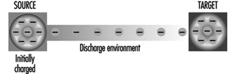
Table 6. Examples of equipment sensitive to electrostatic discharges
|
Sensitive element |
Examples |
|
Source |
An operator touching a door handle or the chassis of a car A |
|
Target |
Electronic components or materials touching a charged operator |
|
Environment |
An explosive mixture ignited by an electrostatic discharge |
Protection of workers
Workers who have reason to believe that they have become electrically charged (for example, when dismounting from a vehicle in dry weather or walking with certain types of shoes), can apply a number of protective measures, such as the following:
- Reduce the current density at the skin level by touching a grounded conductor with a piece of metal such as a key or tool.
- Reduce the peak value of the current by discharging to a dissipating object, if one is available (a table top or special device such as a protective wrist strap with serial resistance).
Protection in explosive atmospheres
In explosive atmospheres, it is the environment itself that is sensitive to electrostatic discharges, and discharges may result in ignition or explosion. Protection in these cases consists of replacing the air, either with a gas mixture whose oxygen content is less than the lower explosive limit, or with an inert gas, such as nitrogen. Inert gas has been used in silos and in reaction vessels in the chemical and pharmaceutical industries. In this case, adequate precautions to assure that workers receive an adequate air supply are needed.