- You are here:
-
Home

-
Contents
-
Part XII. Chemical Industries
- Chemical Processing

77. Chemical Processing
Chapter Editors: Jeanne Mager Stellman and Michael McCann
Table of Contents
Tables and Figures
Chemical Industry
L. De Boer
Developing a Process Safety Management Programme
Richard S. Kraus
Major Unit Operations and Processes: An Overview
Sydney Lipton
Examples of Chemical Processing Operations
Chlorine and Caustic Production
The Chlorine Institute, Inc.
Paint and Coating Manufacture
Michael McCann
Plastics Industry
P.K. Law and T.J. Britton
Biotechnology Industry
Susan B. Lee and Linda B. Wolfe
Pyrotechnics Industry
J. Kroeger
Tables
Click a link below to view table in article context.
1. Chemical industry employment in selected countries
2. Some general site selection factors
3. Plant siting safety considerations
4. Facilities generally separated in overall plant layouts
5. General considerations in a process unit layout
6. Steps for limiting inventory
7. Tank separation & location considerations
8. Pumps in the chemicals process industry
9. Potential explosion sources in equipment
10. Volatile products of the decomposition of plastics
11. Microorganisms of industrial importance
12. Raw materials used in the manufacture of pyrotechnics
Figures
Point to a thumbnail to see figure caption, click to see figure in article context.
|
|


Children categories

Examples of Chemical Processing Operations (5)
Examples of Chemical Processing Operations
Chemical Industry
Adapted from 3rd edition, Encyclopaedia of Occupational Health and Safety.
The business of the chemical industry is to change the chemical structure of natural materials in order to derive products of value to other industries or in daily life. Chemicals are produced from these raw materials-principally minerals, metals and hydrocarbons-in a series of processing steps. Further treatment, such as mixing and blending, is often required to convert them into end-products (e.g., paints, adhesives, medicines and cosmetics). Thus the chemical industry covers a much wider field than what is usually called “chemicals” since it also includes such products as artificial fibres, resins, soaps, paints, photographic films and more.
Chemicals fall into two main classes: organic and inorganic. Organic chemicals have a basic structure of carbon atoms, combined with hydrogen and other elements. Oil and gas are today the source of 90% of world organic chemical production, having largely replaced coal and vegetable and animal matter, the earlier raw materials. Inorganic chemicals are derived chiefly from mineral sources. Examples are sulphur, which is mined as such or extracted from ores, and chlorine, which is made from common salt.
The products of the chemical industry can be broadly divided into three groups, which correspond to the principal steps in manufacture: base chemicals (organic and inorganic) are normally manufactured on a large scale and are normally converted to other chemicals; intermediates are derived from base chemicals. Most intermediates require further processing in the chemical industry, but some, such as solvents, are used as they are; finished chemical products are made by further chemical processing. Some of these (drugs, cosmetics, soaps) are consumed as such; others, such as fibres, plastics, dyes and pigments, are processed still further.
The main sectors of the chemical industry are as follows:
- basic inorganics: acids, alkalis and salts, mainly used elsewhere in industry and industrial gases, such as oxygen, nitrogen and acetylene
- basic organics: feedstocks for plastics, resins, synthetic rubbers, and synthetic fibres; solvents and detergent raw materials; dyestuffs and pigments
- fertilizers and pesticides (including herbicides, fungicides and insecticides)
- plastics, resins, synthetic rubbers, cellulosic and synthetic fibres
- pharmaceuticals (drugs and medicines)
- paints, varnishes and lacquers
- soaps, detergents, cleaning preparations, perfumes, cosmetics and other toiletries
- miscellaneous chemicals, such as polishes, explosives, adhesives, inks, photographic film and chemicals
In the International Standard Industrial Classification of All Economic Activities (ISIC) system, used by the United Nations to classify economic activity into ten major divisions, the chemical industry is classified as Division 35, one of the nine subdivisions of Major Division 3: Manufacturing. Division 35 is further subdivided into industrial chemicals (351), other chemicals (352), petroleum refineries (353), miscellaneous coal and petroleum products, e.g., asphalt (354), rubber products including tyres (355) and plastics processing (356).
In reporting chemical industry statistics each country normally uses its own classification system, and this can be misleading. Thus comparison between countries of total chemical industry performance cannot be based on national sources. However, international bodies like the Organization for Economic Cooperation and Development (OECD) and the United Nations normally supply data on the ISIC basis, though with a delay of about two years.
Trade statistics are published internationally under the Standard International Trade Classification (SITC), which differs from the ISIC system. Trade statistics by individual countries nearly always refer to SITC section 5, which covers about 90% of total chemicals reported in the ISIC system.
The chemical industry has grown much more rapidly in the half century than industry as a whole. Although there was an economic depression in the world’s chemical industry in the early 1990s, chemical production increased in the mid-1990s. The biggest area of growth of chemical production has been in Southeast Asia. Figure 1 shows the percentage change in chemical production for 1992-95 for selected countries.
Figure 1.Change in chemical production for selected countries, 1992-95

Much of the chemical industry is highly capital-intensive and is also strongly dependent on research and development (e.g., pharmaceuticals). The combined result of these two factors is that the industry employs an abnormally low number of unskilled manual workers for its size, in comparison with manufacturing industry in general. Total employment in the industry rose slightly during the period of rapid growth prior to 1970, but since then the drive for increased productivity has resulted in a decline in employment in the chemical industry in most developed countries. Table 1 shows chemical industry employment in the United States and several European countries for 1995.
Table 1. Chemical industry employment in selected countries (1995)
|
Country |
Employment |
|
United States |
1, 045,000 |
|
Germany |
538,000 |
|
France |
248,000 |
|
United Kingdom |
236,000 |
|
Italy |
191,000 |
|
Poland |
140,000 |
|
Spain |
122,000 |
Source: Chemical and Engineering News 1996.
Chlorine and Caustic Production
The Chlorine Institute, Inc.
Electrolysis of salt brines produces chlorine and caustic. Sodium chloride (NaCl) is the primary salt used; it yields caustic soda (NaOH). However, the use of potassium chloride (KCl) produces caustic potash (KOH).
2 NaCl + 2 H2O → Cl2↑+ 2 NaOH + H2↑
salt + water → chlorine (gas) + caustic + hydrogen (gas)
Currently the diaphragm cell process is in greatest use for the commercial production of chlorine followed by the mercury cell process and then the membrane cell process. Due to economic, environmental and product quality issues, manufacturers now prefer the membrane cell process for new production facilities.
The Diaphragm Cell Process
A diaphragm cell (see figure 1) is fed saturated salt brine into a compartment containing a titanium anode coated with salts of ruthenium and other metals. A plastic cell head collects the hot, wet chlorine gas produced at this anode. Suction by a compressor then draws the chlorine into a collection header for further processing consisting of cooling, drying and compression. Water and unreacted brine percolate through a porous diaphragm separator into the cathode compartment where water reacts at a steel cathode to produce sodium hydroxide (caustic soda) and hydrogen. The diaphragm keeps the chlorine produced at the anode from the sodium hydroxide and hydrogen produced at the cathode. If these products combine, the result is sodium hypochlorite (bleach) or sodium chlorate. Commercial producers of sodium chlorate use cells that do not have separators. The most common diaphragm is a composite of asbestos and a fluorocarbon polymer. Modern diaphragm cell plants do not have the health or environmental problems historically associated with the use of asbestos diaphragms. Some plants do employ non-asbestos diaphragms, which are now commercially available. The diaphragm cell process produces a weak sodium hydroxide solution containing unreacted salt. An additional evaporation process concentrates the caustic and removes most of the salt to make a caustic of commercial quality.
Figure 1. Types of chloralkali cell processes
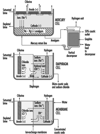
The Mercury Cell Process
A mercury cell actually consists of two electrochemical cells. The reaction in the first cell at the anode is:
2 Cl– → C12 + 2 e–
chloride → chlorine + electrons
The reaction in the first cell at the cathode is:
Na+ + Hg + e– → Na · Hg
sodium ion + mercury + electrons → sodium amalgam
Salt brine flows in an inclined steel trough with rubber-lined sides (see figure 4) Mercury, the cathode, flows under the brine. Anodes of coated titanium are suspended in the brine for the production of chlorine, which exits the cell to a collection and processing system. Sodium is electrolyzed in the cell and leaves the first cell amalgamated with the mercury. This amalgam flows into a second electrochemical cell called the decomposer. The decomposer is a cell with graphite as a cathode and the amalgam as the anode.
The reaction in the decomposer is:
2 Na•Hg + 2 H2O → 2 NaOH + 2 Hg + H2 ↑
The mercury cell process produces commercial (50%) NaOH directly from the cell.
The Membrane Cell Process
The electrochemical reactions in a membrane cell are the same as in the diaphragm cell. A cation-exchange membrane is used in place of the porous diaphragm (see figure 1). This membrane prevents the migration of chloride ions into the catholyte, thereby producing essentially salt free 30 to 35% caustic directly from the cell. The elimination of the need to remove salt makes the evaporation of the caustic to commercial 50% strength simpler, and it requires less investment and energy. Expensive nickel is used as the cathode in the membrane cell due to the stronger caustic.
Safety and Health Hazards
At ordinary temperatures, dry chlorine, either liquid or gas, does not corrode steel. Wet chlorine is highly corrosive because it forms hydrochloric and hypochlorous acids. Precautions should be taken to keep chlorine and chlorine equipment dry. Piping, valves and containers should be closed or capped when not in use to keep out atmospheric moisture. If water is used on a chlorine leak the resulting corrosive conditions will make the leak worse.
The volume of liquid chlorine increases with temperature. Precautions should be taken to avoid hydrostatic rupture of piping, vessels, containers or other equipment filled with liquid chlorine.
Hydrogen is a co-product of all chlorine manufactured by the electrolysis of aqueous brine solutions. Within a known concentration range, mixtures of chlorine and hydrogen are flammable and potentially explosive. The reaction of chlorine and hydrogen can be initiated by direct sunlight, other sources of ultraviolet light, static electricity or sharp impact.
Small quantities of nitrogen trichloride, an unstable and highly explosive compound, can be produced in the manufacturing of chlorine. When liquid chlorine containing nitrogen trichloride is evaporated, the nitrogen trichloride may reach hazardous concentrations in the remaining liquid chlorine.
Chlorine can react, at times explosively, with a number of organic materials such as oil and grease from sources such as air compressors, valves, pumps and oil-diaphragm instrumentation, as well as wood and rags from maintenance work.
As soon as there is any indication of a chlorine release, immediate steps must be taken to correct the condition. Chlorine leaks always get worse if they are not promptly corrected. When a chlorine leak occurs, authorized, trained personnel equipped with respiratory and other appropriate personal protective equipment (PPE) should investigate and take proper action. Personnel should not enter into atmospheres containing concentrations of chlorine in excess of the immediately dangerous to life and health (IDLH) concentration (10 ppm) without appropriate PPE and back-up personnel. Unnecessary personnel should be kept away and the hazard area should be isolated. Persons potentially affected by a chlorine release should be evacuated or sheltered in place as circumstances warrant.
Area chlorine monitors and wind direction indicators can supply timely information (e.g., escape routes) to help determine whether personnel are to be evacuated or sheltered in place.
When evacuation is utilized, potentially exposed persons should move to a point upwind of the leak. Because chlorine is heavier than air, higher elevations are preferable. To escape in the shortest time, persons already in a contaminated area should move crosswind.
When inside a building and sheltering in place is selected, shelter can be achieved by closing all windows, doors and other openings, and turning off air conditioners and air intake systems. Personnel should move to the side of the building furthest from the release.
Care must be taken not to position personnel without an escape route. A safe position may be made hazardous by a change in wind direction. New leaks may occur or the existing leak may get larger.
If fire is present or imminent, chlorine containers and equipment should be moved away from the fire, if possible. If a non-leaking container or equipment cannot be moved, it should be kept cool by applying water. Water should not be used directly on a chlorine leak. Chlorine and water react forming acids and the leak quickly will get worse. However, where several containers are involved and some are leaking, it may be prudent to use a water spray to help prevent overpressure of the non-leaking containers.
Whenever containers have been exposed to flames, cooling water should be applied until well after the fire is out and the containers are cooled. Containers exposed to fire should be isolated and the supplier should be contacted as soon as possible.
Sodium hydroxide solutions are corrosive, especially when concentrated. Workers at risk for exposure to spills and leaks should wear gloves, face shield and goggles and other protective clothing.
Acknowledgements: Dr. R.G. Smerko is acknowledged for making available the resources of the Chlorine Institute, Inc.
Developing a Process Safety Management Programme
Whenever there are processes that use temperature and pressure to change the molecular structure or create new products from chemicals, the possibility exists for fires, explosions or releases of flammable or toxic liquids, vapours, gases or process chemicals. The control of these undesired events requires a special science called process safety management. The terms process safety and process safety management are most commonly used to describe the protection of employees, the public and the environment from the consequences of undesirable major incidents involving flammable liquids and highly hazardous materials. According to the United States Chemical Manufacturers’ Association (CMA), “process safety is the control of hazards which are caused by maloperation or malfunction of the processes used to convert raw materials into finished products, which may lead to the unplanned release of hazardous material” (CMA 1985).
Industry and labour process safety involvement
Process safety technology has played an important role in the chemical processing industries so that handling flammable and combustible liquids and gases could proceed without undesirable consequences. During the 1980s, the oil and gas industries, for example, recognized that process safety technology alone, without process safety management, would not prevent catastrophic incidents. With this in mind, a number of industry associations, such as, in the United States, the Center for Chemical Process Safety (CCPS), the American Petroleum Institute (API) and the Chemical Manufacturers' Association (CMA), initiated programmes to develop and provide process safety management guidelines for use by their members. As stated by the CCPS, "The evolution of process safety from a purely technical issue to one that demanded management approaches was essential to continued process safety improvement".
The CCPS was formed in 1985 to promote the improvement of process safety management techniques among those who store, handle, process and use hazardous chemicals and materials. In 1988, the Chemical Manufacturer's Association (CMA) initiated its Responsible Care® programme outlining each member company's commitment to environmental, health and safety responsibility in managing chemicals.
In 1990, the API initiated an industry-wide programme entitled, STEP-Strategies for Today's Environmental Partnership, with the intention of improving the oil and gas industry's environmental, health and safety performance. One of the seven strategic elements of the STEP programme covers petroleum operating and process safety. The following documents are examples of some of the materials developed as a result of the STEP programme which provide guidance to the oil and gas industry to help prevent the occurrence or minimize the consequences of catastrophic releases of flammable liquids and vapours or hazardous process materials:
- Management of Process Hazards (RP 750)
RP 750 covers the management of hydrocarbon process hazards in design, construction, start-up, operations, inspection, maintenance and facility modifications. It applies specifically to refineries, petro-chemical plants and major processing facilities that use, produce, process or store flammable liquids and toxic processing chemicals in quantities above certain hazardous amounts (as defined therein).
- Management of Hazards Associated with Location of Process Plant Buildings (RP 752)
RP 752, co-developed by API and CMA, is intended to help identify process plant buildings of concern, understand the potential hazards related to their location within the process facility and manage the risk of fire, explosion and toxic releases.
- Management Practices, Self-assessment Process, and Resource Materials (RP 9000)
RP 9000 provides resource materials and self assessment methodology to measure progress in implementing process safety management elements.
Examples of other organizations which have developed materials and programmes providing guidance covering chemical process safety management include, but are not limited to, the following:
- Organizations Resource Counselors' (ORC) report, Process Hazards Management of Substances with Catastrophic Potential
- National Petroleum Refiners Association (NPRA), BEST (Building Environmental Stewardship Tools) programme
- International Labour Organization (ILO), Code of Practice on the Prevention of Major Accident Hazards
- International Chamber of Commerce (ICC), Charter for Sustainable Development.cmp01ce.doc
The process design and technology, changes in the process, materials and changes in materials, operations and maintenance practices and procedures, training, emergency preparedness and other elements affecting the process must all be considered in the systematic identification and evaluation of hazards so as to determine whether or not they have the potential to lead to a catastrophe in the workplace and surrounding community.
Beginning in the early 1980s, a number of serious major incidents occurred in the petroleum and chemical industries involving highly hazardous materials, which resulted in considerable numbers of fatalities and injuries and significant property losses. These incidents provided the impetus for government agencies, labour organizations and industry associations throughout the world to develop and implement codes, regulations, procedures and safe work practices directed toward the elimination or mitigation of these undesirable events, through the application of the principles of process safety management. They are discussed more fully in the Disasters, natural and technological chapter and elsewhere in this Encyclopaedia.
In response to public concern over the potential hazards of chemicals, governments and regulatory agencies throughout the world initiated programmes which required manufacturers and users to identify hazardous materials in the workplace and inform employees and consumers of the hazards presented by their manufacture, use, storage and handling. These programmes, which covered emergency preparedness and response, hazard recognition, product knowledge, control of hazardous chemicals and reporting of toxic releases, included hydrocarbon processing.
Process Safety Management Requirements
Process safety management is an integral part of the overall chemical processing facility safety programme. An effective process safety management programme requires the leadership, support and involvement of top management, facility management, supervisors, employees, contractors and contractor employees.
Components to be considered when developing a process safety management programme include:
- Interdependent continuity of operations, systems and organization
- Management of information. The process safety management programme relies upon providing availability and access to good records and documentation.
- Control of process quality, deviations and exceptions and alternate methods
- Management and supervisory accessibility and communications. Because process safety management is the basis for all safety efforts within the facility, managerial, supervisory and employee responsibility and accountability should be clearly delineated, communicated and understood in order for the programme to work.
- Goals and objectives, compliance audits and performance measurement. Prior to implementation, it is important to establish both long-term and short-term goals and objectives for each of the elements of the process safety management programme.
Elements of the Process Safety Management Programme
All chemical facility process safety management programmes cover the same basic requirements, although the number of programme elements may vary depending on the criteria used. Regardless which government, company or association source document is used as a guide, there are a number of basic requirements which should be included in every chemical process safety management programme:
- process safety information
- employee involvement
- process hazard analysis
- management of change
- operating procedures
- safe work practices and permits
- employee information and training
- contractor personnel
- pre-startup safety reviews
- design quality assurance
- maintenance and mechanical integrity
- emergency response
- periodic safety audits
- process incident investigation
- standards and regulations
- trade secrets.
Process safety information
Process safety information is used by the process industry to define critical processes, materials and equipment. Process safety information includes all available written information concerning process technology, process equipment, raw materials and products and chemical hazards before conducting a process hazard analysis. Other critical process safety information is documentation relating to capital project reviews and design basis criteria.
Chemical information includes not only the chemical and physical properties, reactivity and corrosive data and thermal and chemical stability of chemicals such as hydrocarbons and highly hazardous materials in the process, but also the hazardous effects of inadvertently mixing different incompatible materials. Chemical information also includes that which may be needed to conduct environmental hazard assessments of toxic and flammable releases and permissible exposure limits.
Process technology information includes block flow diagrams and/ or simple process flow diagrams as well as descriptions of the chemistry of each specific process with the safe upper and lower limits for temperatures, pressures, flows, compositions and, where available, process design material and energy balances. The consequences of deviations in the process and materials, including their effect on employee safety and health, are also determined. Whenever processes or materials are changed, the information is updated and re-evaluated in accordance with the facility’s management of change system.
Process equipment and mechanical design information includes documentation covering the design codes employed and whether or not equipment complies with recognized engineering practices. A determination is made as to whether existing equipment which was designed and constructed in accordance with codes, standards and practices no longer in general use is maintained, operated, inspected and tested to assure continued safe operation. Information on materials of construction, piping and instrument diagrams, relief system design, electrical classification, ventilation design and safety systems is updated and re-evaluated when changes occur.
Employee involvement
Process safety management programmes should include employee participation in the development and conduct of process safety analyses and other elements of the programme. Access to process safety information, incident investigation reports and process hazard analyses is usually provided to all employees and contractor employees working in the area. Most industrialized nations require that workers be systematically instructed in the identification, nature and safe-handling of all chemicals to which they may be exposed.
Process hazard analysis
After the process safety information is compiled, a thorough and systematic multi-disciplinary process hazard analysis, appropriate to the complexity of the process, is conducted in order to identify, evaluate and control the hazards of the process. Persons performing the process hazard analysis should be knowledgeable and experienced in relevant chemistry, engineering and process operations. Each analysis team normally includes at least one person who is thoroughly familiar with the process being analysed and one person who is competent in the hazard analysis methodology being used.
The priority order used to determine where within the facility to begin conducting process hazard analyses is based on the following criteria:
- extent and nature of the process hazards
- number of potentially affected workers
- operating and incident history of the process
- age of the process.
A number of methods for conducting process safety analyses are used in the chemical industry.
The “what if?” method asks a series of questions to review potential hazard scenarios and possible consequences and is most often used when examining proposed modifications or changes to the process, materials, equipment or facility.
The “checklist” method is similar to the “what if?” method, except that a previously developed checklist is used which is specific to the operation, materials, process and equipment. This method is useful when conducting pre-startup reviews upon completion of initial construction or following major turnarounds or additions to the process unit. A combination of the “what if?” and “checklist” methods is often used when analysing units that are identical in construction, materials, equipment and process.
The hazard and operability (HAZOP) study method is commonly used in the chemical and petroleum industries. It involves a multi-disciplinary team, guided by an experienced leader. The team uses specific guide words, such as “no”, “increase”, “decrease” and “reverse”, which are systematically applied to identify the consequences of deviations from design intent for the processes, equipment and operations being analysed.
Fault tree/event tree analyses are similar, formal deductive techniques used to estimate the quantitative likelihood of an event occurring. Fault tree analysis works backward from a defined incident to identify and display the combination of operational errors and/ or equipment failures which were involved in the incident. Event tree analysis, which is the reverse of fault tree analysis, works forwards from specific events, or sequences of events, in order to pinpoint those that could result in hazards, and thereby calculate the likelihood of an event’s sequence occurring.
The failure mode and effects analysis method tabulates each process system or unit of equipment with its failure modes, the effect of each potential failure on the system or unit and how critical each failure could be to the integrity of the system. The failure modes are then ranked in importance to determine which is most likely to cause a serious incident.
No matter which method is used, all chemical process hazard analyses consider the following:
- process location, siting and hazards of the process
- identification of any prior incident or near miss with potential catastrophic consequences
- engineering and administrative controls applicable to the hazards
- interrelationships of controls and appropriate application of detection methodology to provide early warnings
- consequences of human factors, facility siting and failure of the controls
- consequences of safety and health effects on workers within areas of potential failure.
Management of change
Chemical process facilities should develop and implement programmes which provide for the revision of process safety information, procedures and practices as changes occur. Such programmes include a system of management authorization and written documentation for changes to materials, chemicals, technology, equipment, procedures, personnel and facilities that affect each process.
Management of change programmes in the chemical industry, for example, include the following areas:
- change of hydrocarbon process technology
- changes in facility, equipment or materials (e.g., catalysts or additives)
- management of change personnel and organizational and personnel changes
- temporary changes, variances and permanent changes
- enhancement of process safety knowledge, including:
- technical basis for proposed change
- impact of change on safety, health and environment
- modifications to operating procedures and safe work practices
- modifications required to other processes
- time required for the change
- authorization requirements for the proposed change
- updating documentation relating to process information, operating procedures and safety practices
- required training or education due to change
- management of subtle change (anything which is not replacement in kind)
- non-routine changes.
The management of change system includes informing employees involved in the process and maintenance and contractor personnel whose tasks would be affected by any changes of the changes and providing updated operating procedures, process safety information, safe work practices and training as needed, prior to the startup of the process or affected part of the process.
Operating procedures
Chemical processing facilities must develop and provide operating instructions and detailed procedures to workers. Operating instructions should be regularly reviewed for completeness and accuracy (and updated or amended as changes occur) and cover the process unit’s operating limits, including the following three areas:
- consequences of deviation
- steps to avoid or correct deviation
- functions of safety systems related to operating limits.
Workers involved in the process have access to operating instructions covering the following areas:
- initial startup (startup after turnarounds, emergencies and temporary operations)
- normal startup (normal and temporary operations and normal shutdown)
- emergency operations and emergency shutdown
- conditions under which emergency shutdown is required and assignment of shutdown responsibilities to qualified operators
- non-routine work
- operator-process and operator-equipment interface
- administrative controls vs. automated controls.
Safe work practices
Chemical process facilities should implement hot-work and safe work permit and work order programmes to control work conducted in or near process areas. Supervisors, employees and contractor personnel must be familiar with the requirements of the various permit programmes, including permit issuance and expiration and appropriate safety, materials handling and fire protection and prevention measures.
The types of work included in typical chemical facility permit programmes include the following:
- hot work (welding, hot tapping, internal combustion engines, etc.)
- lockout/tagout of electrical, mechanical, pneumatic energy and pressure
- confined-space entry and use of inert gas
- venting, opening and cleaning process vessels, tanks, equipment and lines
- control of entry into process areas by non-assigned personnel.
Chemical facilities should develop and implement safe work practices to control potential hazards during process operations, covering the following areas of concern:
- properties and hazards of materials, catalysts and chemicals used in the process
- engineering, administrative and personal protection controls to prevent exposures
- measures to be taken in event of physical contact or exposure with hazardous chemical
- quality control of raw materials, catalysts and inventory control of hazardous chemicals
- safety and protection system (interlock, suppression, detection, etc.) functions
- special or unique hazards in the workplace.
Employee information and training
Chemical process facilities should use formal process safety training programmes to train and educate incumbent, reassigned and new supervisors and workers. The training provided for chemical process operating and maintenance supervisors and workers should cover the following areas:
- required skills, knowledge and qualifications of process employees
- selection and development of process related training programmes
- measuring and documenting employee performance and effectiveness
- design of process operating and maintenance procedures
- overview of process operations and process hazards
- availability and suitability of materials and spare parts for the processes in which they are to be used
- process start-up, operating, shut-down and emergency procedures
- safety and health hazards related to the process, catalysts and materials
- facility and process area safe work practices and procedures.
Contractor personnel
Contractors are often employed in chemical processing facilities. The facilities must institute procedures to assure that contractor personnel performing maintenance, repair, turnaround, major renovation or specialty work are fully aware of the hazards, materials, processes, operating and safety procedures and equipment in the area. Periodic evaluations of performance are made to assure that contractor personnel are trained, qualified, follow all safety rules and procedures and are informed and aware of the following:
- potential fire, explosion and toxic release hazards related to their work
- plant safety procedures and contractor safe work practices
- emergency plan and contractor personnel actions
- controls for contractor personnel entry, exit and presence in process areas.
Pre-startup safety reviews
Pre-startup process safety reviews are conducted in chemical plants prior to startup of new process facilities and introduction of new hazardous materials or chemicals into facilities, following a major turnaround and where facilities have had significant process modifications.
The pre-startup safety reviews assure the following have been accomplished:
- construction, materials and equipment are verified as in accordance with design criteria
- process systems and hardware, including computer control logic, have been inspected, tested and certified
- alarms and instruments are inspected, tested and certified
- relief and safety devices and signal systems are inspected, tested and certified
- fire protection and prevention systems are inspected, tested and certified
- safety, fire prevention and emergency response procedures are developed, reviewed, in place and are appropriate and adequate
- startup procedures are in place and proper actions have been taken
- a process hazard analysis has been performed and all recommendations addressed, implemented or resolved and actions documented
- all required initial and/ or refresher operator and maintenance personnel training, including emergency response, process hazards and health hazards, is completed
- all operating procedures (normal and upset), operating manuals, equipment procedures and maintenance procedures are completed and in place
- management of change requirements for new processes and modifications to existing processes have been met.
Design Quality Assurances
When new processes or major changes to existing processes are undertaken, a series of process safety design reviews are normally conducted before and during construction (prior to the pre-startup review). The design control review, conducted just before plans and specifications are issued as “final design drawings”, covers the following areas:
- plot plan, siting, spacing, electrical classification and drainage
- hazards analysis and process chemistry design
- project management requirements and qualifications
- process equipment and mechanical equipment design and integrity
- piping and instrument drawings
- reliability engineering, alarms, interlocks, reliefs and safety devices
- materials of construction and compatibility.
Another review is normally conducted just prior to the start of construction covering the following:
- demolition and excavation procedures
- control of raw materials
- control of construction personnel and equipment on facility and site
- fabrication, construction and installation procedures and inspection.
One or more reviews are usually conducted during the course of construction or modification to assure the following areas are in accordance with design specifications and facility requirements:
- materials of construction provided and used as specified
- proper assembly and welding techniques, inspections, verifications and certifications
- chemical and occupational health hazards considered during construction
- physical, mechanical and operational safety hazards considered during construction and facility permit and safety practices followed
- interim protective and emergency response systems provided and working.
Maintenance and mechanical integrity
Process facilities have programmes to maintain ongoing integrity of process-related equipment, including periodic inspection, testing, performance maintenance, corrective action and quality assurance. The programmes are intended to assure that mechanical integrity of equipment and materials is reviewed and certified and deficiencies corrected prior to startup, or provisions made for appropriate safety measures.
Mechanical integrity programmes cover the following equipment and systems:
- pressure vessels and storage tanks
- emergency shutdown and fire protection systems
- process safeguards such as relief and vent systems and devices, controls, interlocks, sensors and alarms
- pumps and piping systems (including components such as valves)
- quality assurance, materials of construction and reliability engineering
- maintenance and preventive maintenance programmes.
Mechanical integrity programmes also cover inspection and testing of maintenance materials, spare parts and equipment to assure proper installation and adequacy for the process application involved. The acceptance criteria and frequency of inspections and tests should conform with manufacturers’ recommendations, good engineering practices, regulatory requirements, industry practices, facility policies or prior experience.
Emergency Response
Emergency preparedness and response programmes are developed to cover an entire process facility and to provide for hazard identification and assessment of potential process hazards. These programmes include training and educating employees and contractor employees in emergency notification, response and evacuation procedures.
A typical process facility emergency preparedness programme complies with applicable company and regulatory requirements and includes the following:
- distinctive employee and/ or community alarm or notification system
- preferred method of internal reporting of fires, spills, releases and emergencies
- requirements for reporting process-related incidents to appropriate government agencies
- emergency shutdown, evacuation, procedures to account for personnel, emergency escape procedures, vehicle and equipment removal and route assignments
- emergency response and rescue procedures, duties and capabilities including employees, public safety, contractors and mutual aid organizations
- procedures for handling small spills or releases of hazardous chemicals
- procedures for providing and safeguarding emergency power and utilities
- business continuation plans, personnel and equipment sources
- document and record preservation, site security, cleanup, salvage and restoration.
Periodic safety audits
Many process facilities use self-evaluation process safety management audits to measure facility performance and assure compliance with internal and external (regulatory, company and industry) process safety requirements. The two basic principles of conducting self evaluation audits are: gathering all of the relevant documentation covering process safety management requirements at a specific facility and determining the programme’s implementation and effectiveness by following up on their application in one or more selected processes. A report of the audit findings and recommendations is developed and facility management maintains documentation which notes how deficiencies had been corrected or mitigated, and if not, reasons why no corrective action had been taken.
Compliance audit programmes in hydrocarbon process facilities cover the following areas:
- establishment of goals, schedule and methods of verification of findings prior to the audit
- determination of the methodology (or format) to be used in conducting the audit, and develop appropriate checklists or audit report forms
- readiness to certify compliance with government, industry and company requirements
- assignment of knowledgeable audit teams (internal and/ or external expertise)
- prompt responses to all findings and recommendations and documentation of actions taken
- maintenance of a copy of at least the most recent compliance audit report on file.
Facility and process unit specific checklists are often developed for use when conducting process safety audits which cover the following items:
- orientation and process safety management programme overview
- preliminary walk-around through the refinery or gas processing facility
- process facility documentation review
- “prior incidents” and near misses (in the process facility or specific unit)
- determination and review of selected process units to be audited
- process unit construction (initial and subsequent modifications)
- process unit chemistry hazards (feedstocks, catalysts, process chemicals, etc.)
- process unit operations
- process unit controls, reliefs and safety systems
- process unit maintenance, repair, testing and inspection
- process unit-related training and employee involvement
- process facility management of change programme, implementation and effectiveness
- process fire protection and emergency notification and response procedures.
Because the objectives and scope of audits can vary, the compliance audit team should include at least one person knowledgeable in the process being audited, one person with applicable regulatory and standards expertise and other persons with the skills and qualifications necessary for conducting the audit. Management may decide to include one or more outside experts on the audit team due to lack of facility personnel or expertise, or because of regulatory requirements.
Process incident investigation
Process facilities have established programmes to thoroughly investigate and analyse process-related incidents and near misses, promptly address and resolve findings and recommendations and review the results with workers and contractors whose jobs are relevant to the incident findings. Incidents (or near misses) are thoroughly investigated as soon as possible by a team which includes at least one person knowledgeable in the process operation involved and others with appropriate knowledge and experience.
Standards and Regulations
Process facilities are subject to two distinct and separate forms of standards and regulations.
- External codes, standards and regulations applicable to the design, operation and protection of process facilities and employees typically include government regulations and association and industry standards and practices.
- Internal policies, guidelines and procedures, developed or adopted by the company or facility to complement external requirements and to cover processes which are distinct or unique, are reviewed periodically and changed when necessary, in accordance with the facility’s management of change system.
Trade Secrets
Process facility management should provide process information, without regard to possible trade secrets or confidentiality agreements, to persons who are:
- responsible for gathering and compiling process safety information
- conducting process hazard analyses and compliance audits
- developing maintenance, operating and safe work procedures
- involved in incident (near miss) investigations
- responsible for emergency planning and response.
Facilities typically require that persons to whom process information is made available enter into agreements not to disclose the information.
Paint and Coating Manufacture
Adapted from NIOSH 1984.
Paints and coatings include paints, varnishes, lacquers, stains, printing inks and more. Traditional paints consist of a dispersion of pigment particles in a vehicle consisting of a film-former or binder (usually an oil or resin) and a thinner (usually a volatile solvent). In addition, there can be a wide variety of fillers and other additives. A varnish is a solution of oil and natural resin in an organic solvent. Synthetic resins may also be used. Lacquers are coatings in which the film dries or hardens entirely by evaporation of the solvent.
Traditional paints were under 70% solids with the remainder being mostly solvents. Air pollution regulations limiting the amount of solvents that can be emitted into the atmosphere have resulted in the development of a wide variety of substitute paints with low or no organic solvents. These include: water-based latex paints; two-part catalysed paints (e.g., epoxy and urethane systems); high solids paints (over 70% solids), including plastisol paints consisting primarily of pigments and plasticizers; radiation-cured paints; and powder coatings.
According to the US National Institute for Occupational Safety and Health (NIOSH 1984), about 60% of paint manufacturers employed fewer than 20 workers, and only about 3% had more than 250 workers. These statistics would be expected to be representative of paint manufacturers worldwide. This indicates a predominance of small shops, most of which would not have in-house health and safety expertise.
Manufacturing Processes
In general, the manufacture of paints and other coatings is a series of unit operations using batch processes. There are few or no chemical reactions; the operations are mostly mechanical. The manufacture involves the assembling of raw materials, mixing, dispersing, thinning and adjusting, filling of containers and warehousing.
Paints
Raw materials used to manufacture paints come as liquids, solids, powders, pastes and slurries. These are manually weighed out and premixed. Agglomerated pigment particles must be reduced to the original pigment size, and the particles must be wet with the binder to ensure dispersion in the liquid matrix. This dispersion process, called grinding, is done with a variety of types of equipment, including high-speed shaft-impeller dispersers, dough mixers, ball mills, sand mills, triple roll mills, pug mills and so forth. After an initial run, which might take as long as 48 hours, resin is added to the paste and the grinding process is repeated for a shorter period. The dispersed material is then transferred by gravity to a let-down tank where additional material such as tinting compounds can be added. For water-based paints, the binder is usually added at this stage. The paste is then thinned with resin or solvent, filtered and then transferred again by gravity to the can filling area. The filling can be done manually or mechanically.
After the dispersion process, it may be necessary to clean the tanks and mills before introducing a new batch. This can involve hand and power tools, as well as alkali cleaners and solvents.
Lacquers
Lacquer production usually is carried out in enclosed equipment such as tanks or mixers in order to minimize evaporation of the solvent, which would result in deposits of a dry lacquer film on processing equipment. Otherwise, lacquer production occurs in the same manner as paint production.
Varnishes
The manufacture of oleoresinous varnishes involves cooking the oil and resin to render them more compatible, to develop high molecular weight molecules or polymers and to increase solubility in the solvent. Older plants may use portable, open kettles for the heating. The resin and oil or resin alone are added to the kettle and then heated to about 316ºC. Natural resins must be heated prior to adding the oils. The materials are poured in over the top of the kettle. During cooking, the kettles are covered with refractory exhaust hoods. After cooking, the kettles are moved to rooms where they are cooled quickly, often by water spray, and then thinner and driers are added.
Modern plants use large closed reactors with capacities of 500 to 8,000 gallons. These reactors are similar to those used in the chemical process industry. They are fitted with agitators, sight-glasses, lines to fill and empty the reactors, condensers, temperature measuring devices, heat sources and so forth.
In both older and modern plants, the thinned resin is filtered as the final step before packaging. This is normally done while the resin is still hot, usually using a filter press.
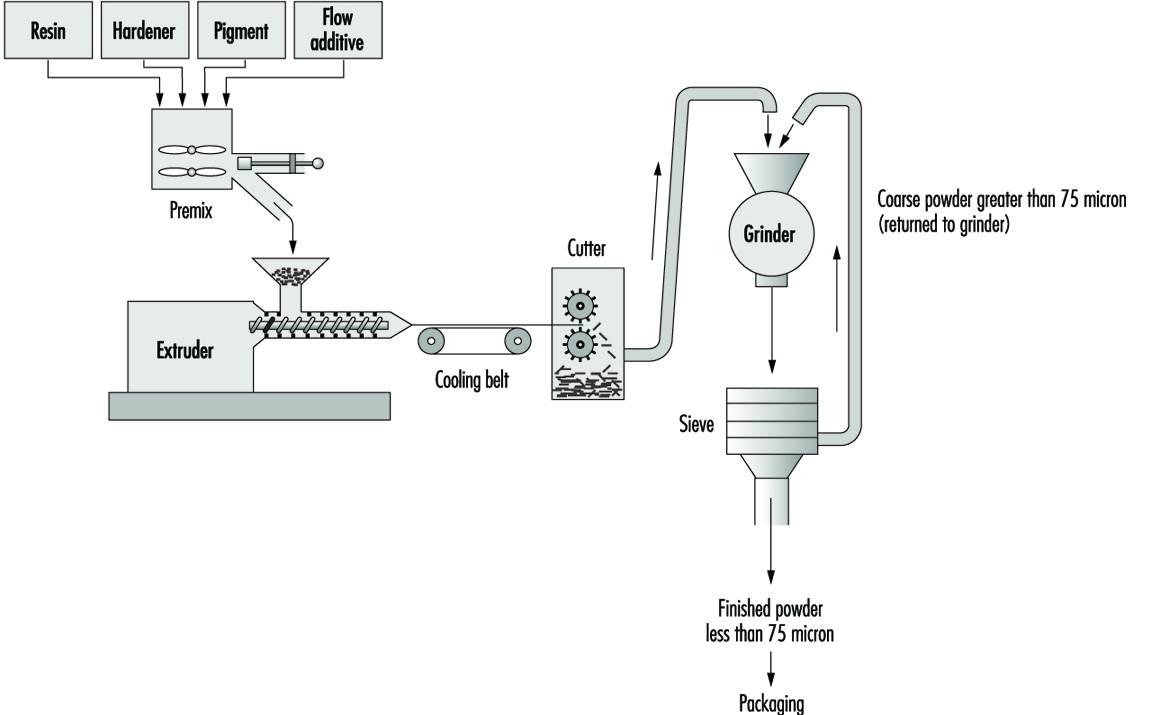
Powder coatings
Powder coatings are solventless systems based on the melting and fusion of resin and other additive particles onto surfaces of heated objects. The powder coatings may be either thermosetting or thermoplastic, and include such resins as epoxies, polyethylene, polyesters, polyvinyl chloride and acrylics.
The most common method of manufacture involves dry blending of the powdered ingredients and extrusion melt-mixing (see figure 1). The dry resin or binder, pigment, filler and additives are weighed and transferred to a premixer. This process is similar to dry blending operations in rubber manufacture. After mixing, the material is placed in an extruder and heated until molten. The molten material is extruded onto a cooling conveyor belt and then transferred to a coarse granulator. The granulated material is passed through a fine grinder and then sieved to achieve the desired particle size. The powder coating is then packaged.
Figure 1. Flow chart for the manufacture of powder coatings by extrusion melt-mixing method
Hazards and Their Prevention
In general, the major hazards associated with the paint and coatings manufacture involve materials handling; toxic, flammable or explosive substances; and physical agents such as electrical shock, noise, heat and cold.
The manual handling of boxes, barrels, containers and so forth which contain the raw materials and finished products are major sources of injury due to improper lifting, slips, falls, dropping containers and so on. Precautions include engineering/ergonomic controls such as materials handling aids (rollers, jacks and platforms) and mechanical equipment (conveyors, hoists and fork-lift trucks), non-skid floors, personal protective equipment (PPE) such as safety shoes and proper training in manual lifting and other materials handling techniques.
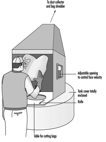
Chemical hazards include exposure to toxic dusts such as lead chromate pigment, which can occur during weighing, filling of mixer and mill hoppers, operations of unenclosed equipment, filling of powdered paint containers, cleaning of equipment and from spills of containers. The manufacture of powder coatings can result in high dust exposures. Precautions include substitution of pastes or slurries for powders; local exhaust ventilation (LEV) for opening bags of powders (see figure 2) and for processing equipment, enclosure of equipment, spill cleanup procedures and respiratory protection when needed.
Figure 2. Bag & dust control system
A wide variety of volatile solvents are used in paint and coating manufacture, including aliphatic and aromatic hydrocarbons, alcohols, ketones and so forth. The most volatile solvents are usually found in lacquers and varnishes. Exposure to solvent vapours can occur during thinning in solvent-based paint manufacture; while charging reaction vessels (especially older kettle types) in varnish manufacture; during can filling in all solvent-based coatings; and during manual cleaning of process equipment with solvents. Enclosure of equipment such as varnish reactors and lacquer mixers usually involves lower solvent exposures, except in the case of leaks. Precautions include enclosure of process equipment, LEV for thinning and can filling operations and respiratory protection and confined-space procedures for cleaning vessels.
Other health hazards include inhalation and/or skin contact with isocyanates used in manufacturing polyurethane paints and coatings; with acrylates, other monomers and photoinitiators used in the manufacture of radiation-curing coatings; with acrolein and other gaseous emissions from varnish cooking; and with curing agents and other additives in powder coatings. Precautions include enclosure, LEV, gloves and other personal protective clothing and equipment, hazardous material training and good work practices.
Flammable solvents, combustible powders (especially nitrocellulose used in lacquer production) and oils are all fire or explosion risks if ignited by a spark or high temperatures. Sources of ignition can include faulty electrical equipment, smoking, friction, open flames, static electricity and so forth. Oil-soaked rags can be a source of spontaneous combustion. Precautions include bonding and grounding containers while transferring flammable liquids, grounding of equipment such as ball mills containing combustible dusts, ventilation to keep vapour concentrations below the lower explosive limit, covering containers when not in use, removal of sources of ignition, using spark-resistant tools of non-ferrous metals around flammable or combustible materials and good housekeeping practices.
Noise hazards can be associated with the use of ball and pebble mills, high speed dispersers, vibrating screens used for filtering and so forth. Precautions include vibration isolators and other engineering controls, replacing noisy equipment, good equipment maintenance, isolation of noise source and a hearing conservation programme where excessive noise is present.
Other hazards include inadequate machine guarding, a common source of injuries around machinery. Electrical hazards are a particular problem if there is not a proper lockout/tagout programme for equipment maintenance and repair. Burns can result from hot varnish cooking vessels and spattering materials and from hot melt glues used for packages and labels.
Major Unit Operations and Processes: An Overview
This article presents information on basic process equipment, storage, plant layout and operations considerations in chemical process industries, including major items and concepts that are broadly applicable throughout the chemical industry. However, much of the equipment required in chemical processing is highly specialized and cannot be broadly generalized. More detailed information on toxicity and hazardous materials and process safety are reviewed elsewhere in this Encyclopaedia.
There are two basic categories of layout in chemical processing industries: plant layout, which covers all process units, utilities, storage areas, loading/unloading areas, buildings, shops and warehousing, and unit or process layout, which covers only equipment placement for a specific process, also termed a process block.
Plant Layout
Siting
Locating or siting an overall plant is based upon a number of general factors, as shown in table 1 (CCPS 1993). These factors vary considerably with locations, governments and economic policies. Of these various factors, safety considerations are an extremely important concern, and in some locations they can be the major factor that governs plant siting.
Table 1. Some general site selection factors
- Population density around the site
- Natural disaster occurrence (earthquake, flood, etc.)
- Prevailing winds and meteorological data
- Availability of power, steam and water
- Safety considerations
- Air, water and waste regulations and their complexity
- Accessibility to raw materials and markets
- Transportation
- Siting permits and complexity of obtaining them
- Interaction requirements in industrial developments
- Labour availability and costs
- Investment incentives
One important aspect of plant safety in siting is defining a buffer zone between a plant with hazardous processes and nearby plants, dwellings, schools, hospitals, highways, waterways and airplane corridors. Some overall safety considerations are presented in table 2. The buffer zone is important because distance tends to reduce or mitigate potential exposures from various accidents. The distance necessary to reduce toxic concentrations to acceptable levels through atmospheric interaction and the dispersion of toxic materials from an accidental release can be defined. Moreover, the time lag between a toxic release and public exposure created by a buffer zone can be used to warn the population through pre-planned emergency response programmes. Since plants have various types of facilities containing toxic materials, dispersion analyses should be conducted on the potentially hazardous systems to ensure the buffer zone is adequate in each area surrounding the plant perimeter.
Table 2. Plant siting safety considerations
- Buffer zone
- Location of other hazardous installations in vicinity
- Inventory of toxic and hazardous materials
- Adequacy of firefighting water supply
- Emergency equipment access
- Availability of emergency response support from adjacent industries and the community
- Weather extremes and prevailing winds
- Location of highways, waterways, railroad and airplane corridors
- Environmental and waste disposal restrictions during emergencies
- Draining and grade slope
- Maintenance and inspection
Fire is a potential hazard in process plants and facilities. Large fires can be a source of thermal radiation which can also be mitigated by distance. Elevated flares can also be a source of thermal radiation during an emergency or startup/shutdown operation. A flare is a device that automatically burns exhaust gases or emergency vapour releases at elevated positions or special ground locations. These should be sited away from the plant perimeter (for community protection) and an area at the flare base should be prohibited to workers. If not operated properly, liquid carryover into the flare can result in burning liquid droplets. In addition to fire, there can be explosions within equipment or a vapour cloud that produces blast waves. Although distance will reduce the blast intensity somewhat over the buffer zone, the blast will still have an effect on the nearby community.
The potential of accidental releases or fires from existing facilities that may be near the proposed site should also be considered. Potential incidents should be modelled and evaluated to determine the possible effect on the proposed plant layout. Emergency responses to an external event should be evaluated and responses coordinated with other plants and affected communities.
Other considerations
Dow Chemical Company has developed another approach to plant layout based on an acceptable level of Maximum Probable Property Damage (MPPD) and Business Interruption Risk (B1) (Dow Chemical Company 1994a). These considerations are important for both new and existing plants. The Dow Fire and Explosion Index is useful in new plant layouts or in the addition of equipment to existing plants. If risks calculated from the Index are found to be unacceptable, the separation distances should be increased. Alternatively, layout changes may also reduce the risk potential.
Overall layout
In an overall plant layout, the prevailing winds are an important consideration. Ignition sources should be located upwind of potential leak sources. Fired heaters, boilers, incinerators and flares are in this category (CCPS 1993). The location of storage tanks downwind of process units and utilities is another recommendation (CCPS 1993). Environmental regulations have led to significantly reduced leakage from tankage (Lipton and Lynch 1994).
Minimum separation distances have been outlined in various publications for process units, equipment and different plant functions (CCPS 1993; Dow Chemical Company 1994a; IRI 1991). General facilities that normally have recommended distance separations in overall plant layouts are shown in table 3. Actual distance recommendations should be carefully defined. While fired heaters and process furnaces are not shown in table 3, they are an important item and recommended distance separations must be included in a unit process layout.
Table 3. Facilities generally separated in overall plant layouts
- Process units
- Tank farms
- Loading and unloading facilities
- Flares
- Power, boilers and incinerators
- Cooling towers
- Substations, large electrical switch yards
- Central control houses
- Warehouses
- Analytical laboratories
- Incoming utility metering and block systems
- Fire hoses, fixed monitors, reservoirs and emergency fire pumps
- Waste treatment areas
- Maintenance buildings and areas
- Administrative buildings
In addition, roads are necessary for emergency and maintenance vehicle or equipment access and require careful placement between process units and throughout the various sections of the plant. Acceptable clearances for overhead pipe racks and other overhead equipment should be established along with lateral clearances at cross-roads and entrances to all facilities.
The layout requirements can be based on recommended minimum separation distances (CCPS 1993; NFPA 1990; IRI 1991; Mecklenburgh 1985) or determined through a hazard analysis (Dow Chemical Company 1994a).
Process Unit Layout
Table 3 presents an overall plant separations layout summary. The process units are contained within the specific block shown in the general layout. The chemical process is generally shown in detail in process and implementation diagrams (P&IDs). A process layout requires considerations beyond specific equipment separation distances, some of which are shown in table 4.
Table 4. General considerations in a process unit layout
- Area definition for future expansion and unit accessibility
- Repair equipment accessibility for frequent maintenance
- Space requirements for individual equipment repair (e.g., area needed for pulling heat exchanger bundle or accessibility for control valve)
- Barriers for high pressure equipment or reactors with explosion potential
- Mechanical and space requirements for loading/unloading solids-filled reactors or towers
- Space for venting dust explosions
- Separation of frequently opened or maintained equipment from high temperature piping, vessels, etc.
- Special buildings or structures and necessary clearance (e.g., a compressor house with an internal bridge crane or external crane)
The assemblage of equipment in any particular process unit will vary considerably, depending on the process. The toxicity and hazardous characteristics of the streams and materials within the units also vary widely. Despite these differences, minimum distance standards have been developed for many equipment items (CCPS 1993; NFPA 1990; IRI 1991; Mecklenburgh 1985). Procedures for calculating potential leakage and toxic exposures from process equipment that can also affect separation distance are available (Dow Chemical Company 1994b). In addition, dispersion analysis can be applied when leakage estimates have been calculated.
Equipment and separation distance
A matrix technique can be used to calculate the space needed for separating equipment (CCPS 1993; IRI 1991). Calculations based upon specific processing conditions and an equipment hazard evaluation may result in separation distances that differ from a standard matrix guide.
Extensive lists for a matrix can be developed by refinement of individual categories and by the addition of equipment. For example, compressors may be split into several types, such as those handling inert gas, air and hazardous gases. Separation distances for engine-driven compressors may differ from motor- or steam-driven machines. Separation distances in storage facilities that house liquefied gases should be analysed on the basis of whether the gas is inert.
The process battery limits should be carefully defined. They are the boundary lines or plot limits for a process unit (the name derives from the early use of a battery of ovens in processing). Other units, roads, utilities, pipeways, runoff ditches and so on are plotted based upon battery limits. While unit equipment location does not extend to the battery limits, separation distances of equipment from battery limits should be defined.
Control rooms or control houses
In the past each process unit was designed with a control room that provided operational control of the process. With the advent of electronic instrumentation and computer-controlled processing, individual control rooms have been replaced by a central control room that controls a number of process units in many operations. The centralized control room is economically advantageous because of process optimization and increases in efficiency of personnel. Individual process units still exist and, in some specialized units, older control houses which have been supplanted by centralized control rooms may still be used for local process monitoring and for emergency control. Although control room functions and locations are generally determined by process economics, the design of the control room or control house is very important for maintaining emergency control and for worker protection. Some considerations for both central and local control houses include:
- pressurizing the control house to prevent the entrance of toxic and hazardous vapours
- designing the control house for blast and explosion resistance
- establishing a location that is at minimal risk (based upon separation distance and probability of gas releases)
- purifying all inlet air and installing an inlet stack location that minimizes the intake of toxic or hazardous vapours
- sealing all sewer outlets from the control house
- installing a fire suppression system.
Inventory reduction
An important consideration in process and plant layouts is the quantity of toxic and hazardous material in the overall inventory, including the equipment. The consequences of a leak are more severe as the volume of material increases. Consequently, the inventory should be minimized wherever possible. Improved processing that reduces the number and size of pieces of equipment reduces the inventory, lowers the risk and also results in lower investment and improved operating efficiencies.
Some potential inventory reduction considerations are shown in table 6. Where a new process facility will be installed, processing should be optimized by taking into consideration some of the objectives shown in table 5.
Table 5. Steps for limiting inventory
- Reducing storage tank inventory reduction through improved process control, operation and just-in-time inventory control
- Eliminating or minimizing onsite tank inventory through process integration
- Using reaction variable analysis and development for reactor volume reduction
- Replacing batch reactors with continuous reactors, which also reduces downstream holdup
- Lowering distillation column holdup through bottoms-volume reductions and tray holdup with either more advanced trays or packings
- Replacing kettle reboilers with thermosyphon reboilers
- Minimizing overhead drum and bottoms surge drum volumes
- Improving pipe layout and sizing to minimize holdup
- Where toxic materials are produced, minimizing the toxic section holdup
Storage Facilities
The storage facilities in a chemical processing plant can house liquid and solid feed, intermediate chemicals, by-products and process products. Products stored in many facilities serve as intermediates or precursors for other processes. Storage may also be required for diluents, solvents or other process materials. All of these materials are generally stored in above-ground storage tankage (AST). Underground tankage is still used in some locations, but use is generally limited due to access problems and limited capacity. In addition, potential leakage of such underground storage tanks (USTs) presents environmental problems when leaks contaminate ground water. General earth contamination can lead to potential atmospheric exposures with higher vapour-pressure materials leaks. Leaked materials can be a potential exposure problem during ground remediation efforts. UST leakage has resulted in stringent environmental regulations in many countries, such as the requirements for double-walled tanks and underground monitoring.
Typical above-ground storage tanks are shown in figure 1. Vertical ASTs are cone or domed roof tanks, floating roof tanks that are covered or non-covered floating roof or external floating roof tanks (EFRTs). Converted or closed roof tanks are EFRTs with covers installed on the tanks that are frequently geodesic type domes. Since EFRTs over time do not maintain a perfectly circular shape, sealing the floating roof is difficult and a covering is installed on the tank. A geodesic dome design eliminates roof trusses needed for cone roof tanks (FRTs). The geodesic dome is more economical than a cone roof and, in addition, the dome reduces losses of materials to the environment.
Figure 1. Typical above-ground storage tanks
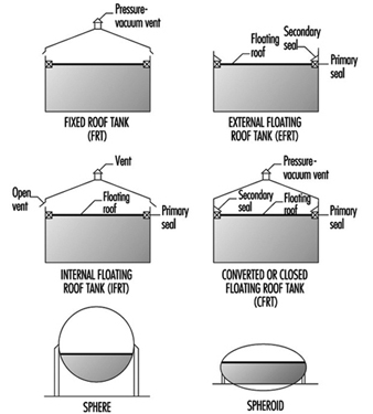
Normally, the tanks are limited to liquid storage where the liquid vapour pressure does not exceed 77 kPa. Where the pressure exceeds this value, spheroids or spheres are used since both are designed for pressure operation. Spheroids can be quite large but are not installed where the pressure may exceed certain limits defined by the mechanical design. For most higher vapour-pressure storage applications, spheres are normally the storage container and are equipped with pressure relief valves to prevent over pressuring. A safety concern that has developed with spheres is rollover, which generates excessive vapour and results in relief valve discharges or in more extreme situations such as sphere wall rupture (CCPS 1993). In general, the liquid contents stratify and if warm (less dense) material is loaded into the sphere bottom, the warm material rises to the surface with the cooler, higher density surface material rolled over to the bottom. The warm surface material vaporizes, raising the pressure, which may result in relief valve discharge or sphere overpressuring.
Tank layout
Tankage layout requires careful planning. There are recommendations for tank separation distances and other considerations (CCPS 1988; 1993). In many locations, separation distances are not specified by code, but minimum distances (OSHA 1994) can be a result of various decisions applicable to separation distances and locations. Some of these considerations are presented in table 6. In addition, tank service is a factor in tank separation for pressurized, refrigerated and atmospheric tanks (CCPS 1993).
Table 6. Tank separation and location considerations
- Separation based on shell to shell distances can be based on references and subject to calculating the thermal radiation distance in the event of fire in an adjacent tank.
- Tanks should be separated from process units.
- A tank location, preferably downwind from other areas, minimizes ignition problems in the event of a tank releasing a significant vapour quantity.
- Storage tanks should have dykes, which are also required by law in most regions.
- Tanks can be grouped for utilization of common dykes and firefighting equipment.
- Dykes should have isolation capability in an emergency.
Dykes are required and are nominally sized volumetrically to hold the contents of a tank. Where multiple tanks are within a dyke, the minimum volumetric dyke capacity is equivalent to the capacity of the largest tank (OSHA 1994). The dyke walls can be constructed of earth, steel, concrete or solid masonry. However, the earth dykes should be impenetrable and have a flat top with a minimum width of 0.61 m. In addition, the soil within the dyked area should also have an impenetrable layer to prevent any chemical or oil leakage into the soil.
Tank leakage
A problem that has been developing through the years is tank leakage as a result of corrosion in the tank bottom. Frequently, tanks have water layers in the tank bottom that can contribute to corrosion, and electrolytic corrosion may occur due to contact with the earth. As a result, regulatory requirements have been instituted in various regions to control tank bottom leakage and underground soil and water contamination from contaminants in the water. A variety of design procedures have been developed to control and monitor leakage (Hagen and Rials 1994). In addition, double bottoms have also been installed. In some installations, cathodic protection has been installed to further control metal deterioration (Barletta, Bayle and Kennelley 1995).
Water draw off
Manually discharging water periodically from the tank bottom can result in exposure. Visual observation to determine the interface through open manual draining can result in worker exposure. A closed discharge can be installed with an interface sensor and control valve minimizing potential worker exposures (Lipton and Lynch 1994). A variety of sensors are commercially available for this service.
Overfilling tanks
Frequently, tanks are overfilled, creating potential safety and worker exposure hazards. This can be prevented with redundant or dual-level instruments controlling inlet block valves or feed pumps (Bahner 1996). For many years, overflow lines were installed on chemical tanks, but they terminated a short distance above a drain opening to permit visual observation of the overflow discharge. Moreover, the drain had to be sized for greater than the maximum fill rate to ensure proper drainage. However, such a system is a potential exposure source. This can be eliminated by connecting the overflow line directly to the drain with a flow indicator in the line to show the overflow. Although this will function satisfactorily, this results in overloading the drain system with a very large contaminant volume and potential health and safety problems.
Tank inspection and cleaning
Periodically, tanks are removed from service for inspection and/ or cleaning. These procedures must be carefully controlled to prevent worker exposure and minimize potential safety hazards. Following draining, tanks are frequently flushed with water to remove process liquid traces. Historically, the tanks have then been cleaned manually or mechanically where necessary. When tanks are drained, they are filled with vapour that may be toxic and can be within a combustible range. Water flushing may not significantly affect vapour toxicity, but it may reduce potential combustion problems. With floating roofs, the material below the floating roof can be flushed and drained, but some tanks may still have material in the sump. This bottom material must be removed manually and may present potential exposure concerns. Personnel may be required to wear personal protective equipment (PPE).
Normally, enclosed tanks and any volume below the floating roofs are purged with air until a specified oxygen concentration level is achieved before entry is permitted. However, concentration measurements should be continually obtained to ensure toxic concentration levels are satisfactory and do not change.
Vapour venting and emission control
For fixed roof or converted floating roof tanks (CFRTs), venting to the atmosphere may not be acceptable in many locations. The pressure-vacuum (PV) vent (shown in figure 2 these tanks are removed and the vapours flow through a closed duct to a control device where the contaminants are destroyed or recovered. For both tanks, an inert purge (e.g., nitrogen) can be injected to eliminate the diurnal vacuum effect and maintain a positive pressure for the recovery device. In the CFRT tank, the nitrogen eliminates the diurnal effect and reduces any vapours to the atmosphere through a PV vent. However, vapour emissions are not eliminated. A large number of control devices and techniques are available including combustion, absorbers, condensers and absorption (Moretti and Mukhopadhyay 1993; Carroll and Ruddy 1993; Basta 1994; Pennington 1996; Siegall 1996). Selection of a control system is a function of final emission targets and operating and investment costs.
In floating roof tanks, both external and internal, seals and auxiliary fitting controls effectively minimize vapour losses.
Safety hazards
Flammability is a major concern in tankage and fire-fighting systems are required to aid in control and prevention of expanded fire zones. Firewater systems and installation recommendations are available (CCPS 1993; Dow Chemical Company 1994a; NFPA 1990). Water can be sprayed directly on a fire under certain conditions and is essential in cooling adjacent tankage or equipment to prevent overheating. In addition, foam is an effective fire-fighting agent and permanent foam equipment can be installed on tanks. The installation of foam equipment on mobile fire-fighting equipment should be reviewed with a manufacturer. Environmentally acceptable and low toxicity foams are now available that are effective and comparable to other foams in quickly extinguishing fires.
Processing Equipment
A wide variety of process equipment is required in chemicals processing as a result of the numerous processes, specialized process requirements and variations in products. Consequently, all of the chemical equipment in use today cannot be reviewed; this section will concentrate on the more widely applied equipment found in processing sequences.
Reactors
There are a large number of reactor types in the chemical industry. The basis for reactor selection is a function of a number of variables, beginning with classifying whether the reaction is a batch or continuous reaction. Frequently, batch reactions are converted to continuous operations as experience with the reaction increases and some modifications, such as improved catalysts, become available. Continuous reaction processing is generally more efficient and produces a more consistent product, which is desirable in meeting product quality targets. However, there are still a large number of batch operations.
Reaction
In all reactions, the classifications of a reaction as exothermic or endothermic (producing heat or requiring heat) is necessary in order to define the heating or cooling requirements necessary to control the reaction. In addition, runaway reaction criteria must be established to install instrument sensors and controls that can prevent a reaction from becoming out of control. Prior to full-scale operation of a reactor, emergency procedures must be investigated and developed to ensure the runaway reaction is safely contained. Some of the various potential solutions are emergency control equipment that is automatically activated, injection of a chemical that stops the reaction and vent facilities that can accommodate and contain the reactor contents. Safety valve and vent operation are extremely important requiring well-maintained and functioning equipment at all times. Consequently, multiple interlocked safety valves are frequently installed to ensure that maintenance on one valve will not reduce the required relief capacity.
Should a safety valve or vent discharge due to malfunction, the discharge effluent must be contained in practically all circumstances to minimize potential safety and health hazards. As a result, the method of containing the emergency discharge through piping along with final disposition of the reactor discharge should be carefully analysed. In general, liquid and vapour should be separated with the vapour sent to a flare or recovery and liquid recycled where possible. Solids removal may require some study.
Batch
In reactors involving exothermic reactions, an important consideration is fouling on the walls or internal tubing by the cooling media used to maintain the temperature. Removal of fouled material varies considerably and the method of removal is a function of the fouled material characteristics. Fouled material can be removed with a solvent, a high-pressure jet nozzle stream or, in some cases, manually. In all these procedures, safety and exposure must be carefully controlled. Movement of material in and out of the reactor must not permit the entrance of air, which may result in a flammable vapour mixture. Vacuums should be broken with an inert gas (e.g., nitrogen). Vessel entry for inspection or work can be classified as entry into a confined space and the rules for this procedure should be observed. Vapour and dermal toxicity should be understood and technicians must be knowledgeable about health hazards.
Continuous
Flow-through reactors can be filled with liquid or a vapour and liquid. Some reactions produce slurries in the reactors. Also, there are reactors that contain solid catalysts. The reaction fluid may be liquid, vapour or a combination of vapour and liquid. Solid catalysts, which promote a reaction without participating in it, are normally contained within grids and are termed fixed beds. The fixed-bed reactors may have single or multiple beds and can have exotherinic or endothermic reactions, with most reactions requiring a constant temperature (isothermal) through each bed. This frequently requires the injection of feed streams or a diluent at various locations between beds to control the temperature. With these reaction systems, temperature indication and sensor location through the beds are extremely important to prevent a reaction runaway and product yield or quality changes.
Fixed beds generally lose their activity and must be regenerated or replaced. For regeneration, deposits on the bed may be burned off, dissolved in a solvent or, in some cases, regenerated through the injection of a chemical in an inert fluid into the bed, thereby restoring catalyst activity. Depending on the catalyst, one of these techniques may be applied. Where beds are burned, the reactor is emptied and purged of all process fluids then filled with an inert gas (usually nitrogen), which is heated and recirculated, raising the bed to a specified temperature level. At this point, a very small volume of oxygen is added to the inert stream to initiate a flame front that gradually moves through the bed and controls the temperature rise. Excessive oxygen quantities have a deleterious effect on the catalyst.
Fixed-bed catalyst removal
Removal of fixed-bed catalysts must be carefully controlled. The reactors are drained of process fluid and then the remaining fluid is displaced with a flushing fluid or purged with a vapour until all of the process fluid has been removed. Final purging may require other techniques before the vessel can be purged with an inert gas or air prior to opening the vessel or discharging the catalyst from the vessel under an inert blanket. Should water be used in this process, the water is drained through closed piping to a process sewer. Some catalysts are sensitive to air or oxygen, becoming pyrophoric or toxic. These require special procedures to eliminate air during filling or emptying the vessels. Personal protection along with handling procedures must be carefully defined to minimize potential exposures and protect personnel.
Spent catalyst disposal may require further treating before it is sent to a catalyst manufacturer for recycling or into an environmentally acceptable disposal procedure.
Other catalyst systems
Gas flowing through a loose solid catalyst bed expands the bed and forms a suspension that is similar to a liquid and termed a fluid bed. This type of reaction is used in various processes. Spent catalysts are removed as a gas-solids side stream for regeneration and then returned to the process through an enclosed system. In other reactions, catalyst activity may be very high and, although catalyst is discharged in the product, the concentration is extremely low and does not pose a problem. Where a high concentration of catalyst solids in the product vapour is undesirable, solids carryover must be removed before purification. However, traces of solids will remain. These are removed for disposal in one of the by-product streams, which in turn must be clarified.
In situations where spent catalyst is regenerated through burning, extensive solids recovery facilities are required in fluid-bed systems to meet environmental restrictions. Recovery may consist of various combinations of cyclones, electric precipitators, bag filters) and/ or scrubbers. Where burning occurs in fixed beds, the basic concern is temperature control.
Since fluid-bed catalysts are frequently within the respiratory range, care must be exercised during solids handling to ensure worker protection with either fresh or recovered catalysts.
In some instances a vacuum may be used to remove various components from a fixed bed. In these situations, a steam-driven vacuum jet is frequently the vacuum producer. This produces a steam discharge that frequently contains toxic materials although in very low concentration in the jet stream. However, the discharge of a steam jet should be carefully reviewed to determine contaminant quantities, toxicity and potential dispersion if it is discharged directly to the atmosphere. Should this be unsatisfactory, the jet discharge may require condensing in a sump where all vapours are controlled and the water is sent to the closed sewer system. A rotary vacuum pump will perform in this service. The discharge from a reciprocating vacuum pump may not be permitted to discharge directly to the atmosphere, but can in some instances discharge into a flare line, incinerator or process heater.
Safety
In all reactors, pressure increases are a major concern since the vessel pressure rating must not be exceeded. These pressure increases may be a result of poor process control, malfunction or a runaway reaction. Consequently, pressure relief systems are required to maintain vessel integrity by preventing reactor overpressuring. Relief valve discharges must be carefully designed to maintain adequate relief under all conditions, including relief-valve maintenance. Multiple valves may be required. Should a relief valve be designed to discharge into the atmosphere, the discharge point should be elevated above all nearby structures and a dispersion analysis should be conducted to ensure adequate protection for workers and nearby communities.
If a rupture disk is installed with a safety valve, the discharge should also be enclosed and the final discharge location designated as described above. Since a disk rupture will not reseat, a disk without a safety valve will probably release most of the reactor contents and air may enter the reactor at the end of the release. This requires a careful analysis to ensure that a flammable situation is not created and that highly undesirable reactions do not occur. Moreover, the discharge from a disk may release liquid and the vent system must be designed to contain all liquids with vapour discharged, as described above. Atmospheric emergency releases must be approved by regulatory authorities before installation.
Mixer agitators installed in reactors are sealed. Leaks may be hazardous and if they occur the seal must be repaired which requires a reactor shutdown. The reactor contents may require special handling or precautions and an emergency shutdown procedure should include reaction termination and disposition of the reactor contents. Flammability and exposure control must be carefully reviewed for each step including final disposition of the reactor mix. Since a shutdown can be expensive and involve production loss, magnetic driven mixers and newer seal systems have been introduced to reduce maintenance and reactor shutdowns.
Entrance to all reactors requires compliance with safe confined-space entry procedures.
Fractionation or distillation towers
Distillation is a process whereby chemical substances are separated through methods which take advantage of differences in boiling points. The familiar towers in chemical plants and refineries are distillation towers.
Distillation in various forms is a processing step found in the great majority of chemical processes. Fractionation or distillation can be found in purification, separation, stripping, azeotropic and extractive process steps. These applications now include reactive distillation, where a reaction occurs in a separate section of the distillation tower.
Distillation is conducted with a series of trays in a tower, or it can be conducted in a tower filled with packing. The packings have special configurations that readily permit the passage of vapour and liquid, but provide sufficient surface area for vapour-liquid contact and efficient fractionation.
Operation
Heat is normally supplied to a tower with a reboiler, although the heat content of specific streams may be sufficient to eliminate the reboiler. With reboiler heat, multiple step vapour-liquid separation occurs on the trays and lighter materials ascend through the tower. Vapours from the top tray are fully or partially condensed in the overhead condenser. The condensed liquid is collected in the distillate recovery drum, where part of the liquid is recycled to the tower and the other portion is withdrawn and sent to a specific location. Non-condensed vapours may be recovered elsewhere or sent to a control device which can be a combustor or recovery system.
Pressure
Towers typically operate at pressures higher than atmospheric pressure. However, towers are frequently operated under vacuum to minimize liquid temperatures that may affect product quality or in situations where tower materials become a mechanical and economic concern due to the temperature level that may be difficult to achieve. Also, high temperatures may affect the fluid. In heavy petroleum fractions, very high tower bottoms temperatures frequently result in coking problems.
Vacuums are typically obtained with ejectors or vacuum pumps. In process units, vacuum loadings consist of some light vapour materials, inerts that may have been in the tower feed stream and air from leakage. Normally the vacuum system is installed after a condenser to reduce the organic loading to the vacuum system. The vacuum system is sized based upon the estimated vapour loading, with ejectors handling larger vapour loadings. In certain systems a vacuum machine may be directly connected to a condenser outlet. A typical ejector system operation is a combination of ejectors and direct barometric condensers where the ejector vapours have direct contact with the cooling water. Barometric condensers are very large consumers of water and the steam-water mixture results in high water outlet temperatures that tend to vaporize any organic compound traces in the atmospheric barometric sump, potentially increasing workplace exposures. In addition, a large effluent load is added to the waste-water system.
A large water reduction is achieved along with a substantial reduction in steam consumption in modified vacuum systems. Since the vacuum pump will not handle a large vapour load, a steam ejector is used in the first stage in combination with a surface condenser to reduce the vacuum pump load. In addition, a sump drum is installed for above-ground operation. The simpler system reduces waste-water loading and maintains a closed system that eliminates potential vapour exposures.
Safety
All towers and drums must be protected from overpressure that may result from malfunction, fire (Mowrer 1995) or utility failure. A hazard review is necessary and is required by law in some countries. A general process safety management approach that is applicable to process and plant operation improves safety, minimizes losses and protects worker health (Auger 1995; Murphy 1994; Sutton 1995). Protection is provided by pressure relief valves (PRVs) that discharge to the atmosphere or to a closed system. The PRV is generally mounted at the tower top to relieve the large vapour load, although some installations locate the PRV in other tower locations. The PRV can also be located on the distillate overhead recovery drum as long as valves are not placed between the PRV and the tower top. If block valves are installed in the process lines to the condenser then the PRV must be installed on the tower.
When distillation tower overpressure is relieved, under certain emergency scenarios, the PRV discharge may be exceedingly large. Very high loading in a closed system discharge vent line may be the largest load in the system. Since a PRV discharge can be sudden and the overall relieving time may be quite short (less than 15 minutes), this extremely large vapour load must be carefully analysed (Bewanger and Krecter 1995; Boicourt 1995). Since this short, large peak load is difficult to process in control devices such as absorbers, adsorbers, furnaces and so on, the preferable control device in most situations is a flare for vapour destruction. Normally, a number of PRVs are connected to a flare line header that in turn is connected to a single flare. However, the flare and overall system must be carefully designed to cover a large group of potential contingencies (Boicourt 1995).
Health hazards
For direct relief to the atmosphere, a detailed dispersion analysis of the relief valve discharge vapours should be conducted to ensure that workers are not exposed and that community concentrations are well within allowable concentration guidelines. In controlling dispersion, atmospheric relief valve discharge lines may have to be raised to prevent excessive concentrations on nearby structures. A very tall flare-like stack may be necessary to control dispersion.
Another area of concern is entering a tower for maintenance or mechanical changes during a shutdown. This entails entering a confined space and exposes workers to the associated hazards. The flushing and purging method prior to opening must be carefully conducted to ensure minimal exposures by reducing any toxic concentrations below recommended levels. Before commencing with flushing and purging operations, the tower pressure must be reduced and all piping connections to the tower must be blinded (i.e., flat metal disks must be placed between the tower flanges and the connecting pipe flanges). This step should be carefully managed to ensure minimum exposures. In different processes, the methods of clearing the tower of toxic fluids vary. Frequently, the tower fluid is displaced with a fluid that has very low toxicity characteristics. This displacement fluid is then drained and pumped to a selected location. The remaining liquid film and droplets can be steamed to the atmosphere through a top flange that has a special stand-off blind with an opening between the blind and tower flange. Following steaming, air enters the tower through the special blind opening as the tower cools. A manhole at the tower bottom and one at the tower top are opened permitting the blowing of air through the tower. When the internal tower concentration reaches a predetermined level, the tower can be entered.
Heat exchangers
There are a wide variety of heat exchangers in the chemical process industry. Heat exchangers are mechanical devices for the transfer of heat to or from a process stream. They are selected in accordance with process conditions and exchanger designs. A few of the common exchanger types are shown in figure 2. Selection of the optimum exchanger for a process service is somewhat complicated and requires a detailed investigation (Woods 1995). In many situations, certain types are not suitable because of pressure, temperature, solids concentration, viscosity, flow quantity and other factors. Moreover, an individual heat exchanger design can vary considerably; several types of floating head tube and sheet exchangers are available (Green, Maloney and Perry 1984). The floating head is normally selected where the temperatures may cause excessive tube expansion that otherwise could not maintain integrity in a fixed tube sheet exchanger. In the simplified floating head exchanger in figure 2, the floating head is contained completely within the exchanger and does not have any connection with the shell cover. In other floating head designs, there may be packing around the floating tubesheet (Green, Maloney and Perry 1984).
Figure 2. Typical heat exchangers

Leakage
The packing on floating tubesheets is in contact with the atmosphere and may be a source of leakage and potential exposure. Other exchangers may also have potential leakage sources and should be examined carefully. As a result of their heat transfer characteristics, plate and frame exchangers are often installed in the chemical industry. The plates have various corrugations and configurations. Plates are separated by gaskets that prevent mixing of the streams and provide an external seal. However, the seals limit temperature applications to about 180 ºC, although seal improvements may overcome this limitation. Since there are a number of plates, the plates must be compressed properly to ensure proper sealing between them. Consequently, careful mechanical installation is necessary to prevent leakage and potential hazards. Since there are a large number of seals, careful seal monitoring is important to minimize potential exposures.
Air cooled exchangers are attractive economically and have been installed in a wide number of process applications and in various locations within process units. To save space, these exchangers are often installed over pipe runs and are frequently stacked. Since tube material selection is important, a variety of materials is used in the chemical industry. These tubes are connected to the tube sheet. This requires use of compatible materials. Leakage through a tube crack or at the tube sheet is a concern since the fan will circulate vapours from the leak and dispersion may result in potential exposures. Air dilution may significantly reduce the potential exposure hazard. However, fans are frequently shut down under some weather conditions and in these circumstances leak concentrations can increase thereby increasing potential exposures. Moreover, if leaking tubes are not repaired, the crack may worsen. With toxic liquids that do not readily vaporize, dripping can occur and result in potential dermal exposure.
Shell and tube heat exchangers may develop leaks through any of the various flanges (Green, Maloney and Perry 1984). Since shell and tube heat exchangers vary in size from small to very large surface areas, the diameter of outer flanges is generally much larger than typical pipe flanges. With these large flanges, the gaskets must not only withstand process conditions, but provide a seal under bolt load variations. Various gasket designs are used. Maintaining constant bolt load stresses on all of the flange bolts is difficult, resulting in leakage in many exchangers. The flange leakage can be controlled with flange sealing rings (Lipton and Lynch 1994).
Tube leakage may occur in any of the available exchanger types, with the exception of plate exchangers and a few other specialty exchangers. However, these latter exchangers have other potential problems. Where tubes leak into a cooling water system, the cooling water discharges the contaminant into a cooling tower which can be an exposure source to both workers and a nearby community. Consequently, the cooling water should be monitored.
The dispersion of cooling tower vapours can be widespread as a result of the fans in forced and induced draft cooling towers. In addition, natural convection towers discharge vapours to the atmosphere which then disperse. However, dispersion varies considerably based upon both weather conditions and the discharge elevation. Less volatile toxic materials remain in the cooling water and the cooling tower blowdown stream, which should have sufficient treatment capability to destroy contaminants. The cooling tower and tower basin must be cleaned periodically and contaminants add to the potential hazards in the basin and in the tower fill. Personal protection is necessary for much of this work.
Exchanger cleaning
A problem with tubes in cooling water service is the build-up of material in the tubes resulting from corrosion, biological organisms and solids deposition. As described above, tubes may also leak through cracks, or leakage may occur where tubes are rolled into striations in the tube sheet. When any of these conditions occur, exchanger repair is required and the process fluids must be removed from the exchanger. This requires a completely contained operation, which is necessary to meet environmental, safety and health exposure objectives.
Generally, the process fluid is drained to a receiver and the remaining material is flushed out of the exchanger with a solvent or inert material. The latter material is also sent to a receiver for the contaminated material by draining or pressuring with nitrogen. Where toxic material was in the exchanger, the exchanger should be monitored for any traces of toxic material. If testing results are unsatisfactory, the exchanger can be steamed to vaporize and remove all traces of material. However, the steam vent should be connected to a closed system to prevent vapour escape into the atmosphere. While the closed vent may not be absolutely necessary, at times there may be more contaminant material in the exchanger, requiring closed steam venting at all times to control potential hazards. Following steaming, a vent to the atmosphere admits air. This general procedure is applicable to the exchanger side or sides containing toxic material.
Chemicals then used for cleaning the tubes or the shell side should be circulated in a closed system. Normally, the cleaning solution is recirculated from a tank truck system and the contaminated solution in the system is drained to a truck for disposition.
Pumps
One of the most important process functions is the movement of liquids and in the chemical industry all types of liquid materials are moved with a wide variety of pumps. Canned and magnetic pumps are sealless centrifugal pumps. Magnetic pump drivers are available for installation on other pump types to prevent leakage. Types of pumps used in the chemical process industry are listed in table 7.
Table 7. Pumps in the chemicals process industry
- Centrifugal
- Reciprocating (plunger)
- Canned
- Magnetic
- Turbine
- Gear
- Diaphragm
- Axial flow
- Screw
- Moving cavity
- Lobe
- Vane
Sealing
From a health and safety standpoint, sealing and repairing centrifugal pumps are major concerns. Mechanical seals, which constitute the prevalent shaft sealing system, can leak and at times have blown out. However, there have been major advances in seal technology since the 1970s that have resulted in significant leakage reductions and extended pump service life. Some of these improvements are bellows seals, cartridge seals, improved face designs, better face materials and improvements in pump variable monitoring. Moreover, continuing research in seal technology should result in further technology improvements.
Where process fluids are highly toxic, leakless or sealless canned or magnetic pumps are frequently installed. Operating service periods or the mean time between maintenance (MTBM) has improved markedly and generally varies between three and five years. In these pumps, the process fluid is the lubricating fluid for the rotor bearings. Vaporization of the internal fluid adversely affects the bearings and often makes bearing replacement necessary. Liquid conditions in the pumps can be maintained by ensuring the internal pressure in the bearing system is always greater than the liquid vapour pressure at the operating temperature. When repairing a sealless pump, completely draining a relatively low volatility material is important and should be carefully reviewed with the supplier.
In typical centrifugal process pumps, packing has essentially been replaced with mechanical seals. These seals are generally classified as single or dual mechanical seals, with the latter term covering tandem or double mechanical seals. There are other dual seal combinations, but they are not as widely used. In general, tandem or double mechanical seals with liquid buffer fluids between the seals are installed to reduce seal leakage. Pump mechanical seal standards for both centrifugal and rotary pumps covering single and dual mechanical seal specification and installation were issued by the American Petroleum Institute (API 1994). A mechanical seal application guide is now available to aid in the evaluation of seal types (STLE 1994).
To prevent excessive leakage or blow-out from a failed seal, a gland plate is installed following the seal. It may have a gland flush fluid to move the leakage into a closed drain system (API 1994). Since the gland system is not a complete seal, auxiliary seal systems, such as throttle bushings are available.They are installed in the gland that controls excessive leakage to the atmosphere or seal blow-out (Lipton and Lynch 1994). These seals are not designed for continuous operation; after activation they will operate for up to two weeks before failure, thereby providing time for operations to switch pumps or make process adjustments.
A newer mechanical seal system is available that essentially reduces emissions to the nil level. This is a double mechanical seal system with a gas buffer system that replaces the liquid buffer in the standard dual mechanical seal system (Fone 1995; Netzel 1996; Adams, Dingman and Parker 1995). In the liquid buffer systems, the seal faces are separated by an extremely thin lubricating film of buffer fluid that also cools the seal faces. Although separated slightly, a certain amount of face contact exists which results in seal wear and seal face heating. The gas seals are called non-contact seals since one seal face with curved indentations pumps gas through the seal faces and builds a gas layer or dam that completely separates the seal faces. This lack of contact results in a very long seal life and also reduces the seal friction loss, thereby noticeably decreasing power consumption. Since the seal pumps gas there is a very small flow into the process and to the atmosphere.
Health hazards
A major concern with pumps is draining and flushing to prepare the pump for maintenance or repair. Draining and removal covers both process fluid and buffer fluids. Procedures should require discharge of all fluids into a closed connection drain system. In the pump stuffing box where a throat bushing separates the impeller from the stuffing box, the bushing acts as a weir in holding some liquid in the stuffing box. Weep holes in the bushing or a drain in the stuffing box will permit complete process liquid removal through draining and flushing. For buffer fluids, there should be a method of draining all fluid from the dual seal area. Maintenance requires seal removal and if the seal volume is not completely drained and flushed, the seals are a potential source of exposure during repair.
Dust and powders
Handling of dusts and powders in solids processing equipment is a concern due to the potential for fire or explosion. An explosion within equipment may burst through a wall or enclosure as a result of explosion-generated pressure sending a combined pressure and fire wave into the workplace area. Workers can be at risk, and adjacent equipment can be severely impacted with drastic effects. Dusts or powders suspended in air or in a gas with oxygen present and in a confined space are susceptible to explosion when a source of ignition with sufficient energy is present. Some typical explosive equipment environments are shown in table 8.
Table 8. Potential explosion sources in equipment
|
Conveying equipment |
Storage |
|
Pneumatic ducts |
Bins |
|
Mechanical conveyors |
Hoppers |
|
Rotary valves |
|
|
Processing equipment |
|
|
Filter dust collectors |
Grinders |
|
Fluid bed dryers |
Ball mills |
|
Transfer line dryers |
Powder mixing |
|
Screening |
Cyclones |
An explosion produces heat and rapid gas expansion (pressure increase) and generally results in deflagration, which is a flame front that moves rapidly but at less than the sound velocity for these conditions. When the flame front velocity is greater than the sound velocity or is at supersonic velocity the condition is termed detonation, which is more destructive than deflagration. Explosion and flame front expansion occur in milliseconds and do not provide sufficient time for standard process responses. Consequently, the potential fire and explosion characteristics of the powder must be defined to determine the potential hazards that may exist in the various processing steps (CCPS 1993; Ebadat 1994; Bartknecht 1989; Cesana and Siwek 1995). This information can then provide a basis for the installation of controls and the prevention of explosions.
Explosion hazard quantification
Since the explosions generally occur in enclosed equipment, various tests are conducted in specially-designed laboratory equipment. While powders may appear similar, published results should not be used since small differences in the powders can have very different explosion characteristics.
A variety of tests conducted on powder can define the explosion hazard and the test series should encompass the following.
The classification test determines whether a powder dust cloud can initiate and propagate flames (Ebadat 1994). Powders that have these characteristics are considered Class A powders. Those powders that do not ignite are termed Class B. The Class A powders then require a further series of tests to evaluate their explosion and hazard potential.
The minimum ignition energy test defines the minimum spark energy necessary for ignition of a powder cloud (Bartknecht 1989).
In explosion severity and analysis Group A powders are then tested as a dust cloud in a sphere where the pressure is measured during a test explosion based on minimum ignition energy. The maximum explosion pressure is defined along with the rate of change in pressure per unit time. From this information, the explosion specific characteristic value (Kst) in bar metres per second is determined and the explosion class is defined (Bartknecht 1989; Garzia and Senecal 1996):
Kst(bar·m/s) Dust explosion class Relative strength
1-200 St 1 Somewhat weaker
201-300 St 2 Strong
300+ St 3 Very strong
A large number of powders have been tested and the majority were in the St 1 class (Bartknecht 1989; Garzia and Senecal 1996).
In assessment of non-cloud powders, powders are tested to determine safe operating procedures and conditions.
Explosion prevention tests
Explosion prevention tests can be helpful where explosion suppression systems cannot be installed. They provide some information on desirable operating conditions (Ebadat 1994).
The minimum oxygen test defines the oxygen level below which the dust will not ignite (Fone 1995). Inert gas in the process will prevent ignition if the gas is acceptable.
The minimum dust concentration is determined in order to establish the operating level below which ignition will not occur.
Electrostatic hazard tests
Many explosions are a result of electrostatic ignitions and various tests indicate the potential hazards. Some of the tests cover the minimum ignition energy, powder electric charge characteristics and volume resistivity. From the test results, certain steps can be taken to prevent explosions. Steps include increasing humidity, modifying construction materials, proper grounding, controlling certain aspects of equipment design and preventing sparks (Bartknecht 1989; Cesana and Siwek 1995).
Explosion control
There are basically two methods of controlling explosions or fronts from propagating from one location and another or containing an explosion within a piece of equipment. These two methods are chemical suppressants and isolation valves (Bartknecht 1989; Cesana and Siwek 1995; Garzia and Senecal 1996). Based upon the explosion pressure data from the explosion severity tests, rapid response sensors are available that will trigger a chemical suppressant and/ or rapidly close isolation barrier valves. Suppressants are commercially available, but suppressant injector design is very important.
Explosion vents
In equipment where a potential explosion may occur, explosion vents that rupture at specific pressures are frequently installed. These must be carefully designed and the exhaust path from the equipment must be defined to prevent a worker presence in this path area. Moreover, impingement on equipment in the explosion path should be analysed to ensure equipment safety. A barrier may be required.
Loading and Unloading
Products, intermediates and by-products are loaded into tank trucks and railcars. (In some cases, depending on location of facilities and dockage requirements, tankers and barges are used.) Location of the loading and unloading facilities are important. While the materials loaded and unloaded usually are liquids and gases, solids are also loaded and unloaded at preferred locations based upon the type of solids moved, potential explosion hazard and the degree of transfer difficulty.
Open hatches
In loading tank trucks or railcars through top opening hatches, a very important consideration is minimizing splashing as the container is filled. If the fill pipe is located well above the bottom of the container, filling results in splashing and generation of vapour or mixed liquid-vapour evolvement. Splashing and vapour generation can be minimized by locating the fill pipe outlet well below the liquid level. The fill pipe is normally extended through the container a minimum distance above the container bottom. Since liquid filling also displaces vapour, toxic vapours can be a potential health hazard and also present safety concerns. Consequently, the vapours should be collected. Fill arms are commercially available that have deep fill pipes and extend through a special cover that closes the hatch opening (Lipton and Lynch 1994). In addition, a vapour collection pipe extends a short distance below the special hatch cover. At the upstream end of the arm, the vapour outlet is connected to a recovery device (e.g., an absorber or condenser), or the vapour can be returned to the storage tank as a vapour balance transfer (Lipton and Lynch 1994).
In the tank truck open hatch system, the arm is raised to permit draining into the tank truck and some of the liquid in the arm can be pressured with nitrogen as the arm is withdrawn, but the fill pipes during this operation should remain within the hatch opening. As the fill arm clears the hatch, a bucket should be placed over the outlet to catch arm drippings.
Railcars
Many railcars have closed hatches with deep fill legs very close to the bottom of the container and a separate vapour collection outlet. Through an arm that extends to the closed hatch, liquid is loaded and vapour collected in a fashion similar to the open hatch arm method. In railcar loading systems, following valve shut off at the arm inlet, nitrogen is injected into the container side of the arms to blow the liquid remaining in the arm into the railcar before the fill valve on the railcar is closed (Lipton and Lynch 1994).
Tank trucks
Many tank trucks are filled through the bottom to minimize vapour generation (Lipton and Lynch 1994). The fill lines can be special hoses or manoeuvrable arms. Dry break couplers are placed on the hose or arm ends and on the tank truck bottom connections. When the tank truck is filled and the line is automatically blocked, the arm or hose is disconnected at the drybreak coupling, which automatically closes as the couplings are separated. Newer couplings have been designed to disconnect with almost zero leakage.
In bottom loading, vapour is collected through a top vapour vent and the vapour is conducted through an external line that terminates near the bottom of the container (Lipton and Lynch 1994). This permits worker access to the vapour coupling connections. The collected vapour, which is at a pressure slightly above atmospheric, must be collected and sent to a recovery device (Lipton and Lynch 1994). These devices are selected based upon initial cost, effectiveness, maintenance and operability. Generally, the recovery system is preferable to a flare, which destroys the recovered vapours.
Loading control
In tank trucks, level sensors are permanently installed within the truck body to indicate when the fill level has been reached and signal a remote control block valve that stops flow to the truck. (Lipton and Lynch 1994). There may be more than one sensor in the tank truck as backup to ensure that the truck is not overfilled. Overfilling can result in serious safety and health exposure problems.
Railcars in dedicated chemical service may have level sensors mounted internally in the car. For non-dedicated cars, a flow totalizer controls the amount of liquid sent to the railcar and automatically shuts the remote control block valve at a predetermined setting (Lipton and Lynch 1994). Both container types should be investigated to determine whether liquid remains in the container prior to filling. Many railcars have manual level indicators that can be used for this service. However, where level is shown by opening a small level stick vent to the atmosphere, this procedure should only be performed under properly controlled and approved conditions due to the toxicity of some of the loaded chemicals.
Unloading
Where chemicals have a very high vapour pressure and the railcar or tank truck has a relatively high pressure, the chemical is unloaded under its own vapour pressure. Should the vapour pressure fall to a level that will interfere with the unloading procedure, nitrogen gas can be injected to maintain a satisfactory pressure. Vapour from a tank of the same chemical can also be compressed and injected to raise the pressure.
For toxic chemicals that have a relatively low vapour pressure, such as benzene, the liquid is unloaded under nitrogen pressure, which eliminates pumping and simplifies the system (Lipton and Lynch 1994). Tank trucks and railcars for this service have design pressures capable of handling the pressures and variations encountered. However, lower pressures after unloading a container are maintained until the tank truck or railcar is refilled; the pressure rebuilds during loading. Nitrogen can be added if sufficient pressure has not been attained during loading.
One of the problems in loading and unloading operations is draining and purging lines and equipment in the loading/unloading facilities. Closed drains and particularly low point drains are necessary with nitrogen purges to remove all traces of the toxic chemicals. These materials can be collected in a drum and returned to a receiving or recovery facility (Lipton and Lynch 1994).
Plastics Industry
Adapted from 3rd edition, Encyclopaedia of Occupational Health and Safety
The plastics industry is divided into two major sectors, the inter-relationship of which can be seen in figure 1. The first sector comprises the raw material suppliers who manufacture polymers and moulding compounds from intermediates which they may also have produced themselves. In terms of invested capital this is usually the largest of the two sectors. The second sector is made up of processors who convert the raw materials into saleable items using various processes such as extrusion and injection moulding. Other sectors include machinery manufacturers who supply equipment to the processors and suppliers of special additives for use within the industry.
Figure 1. Production sequence in the processing of plastics
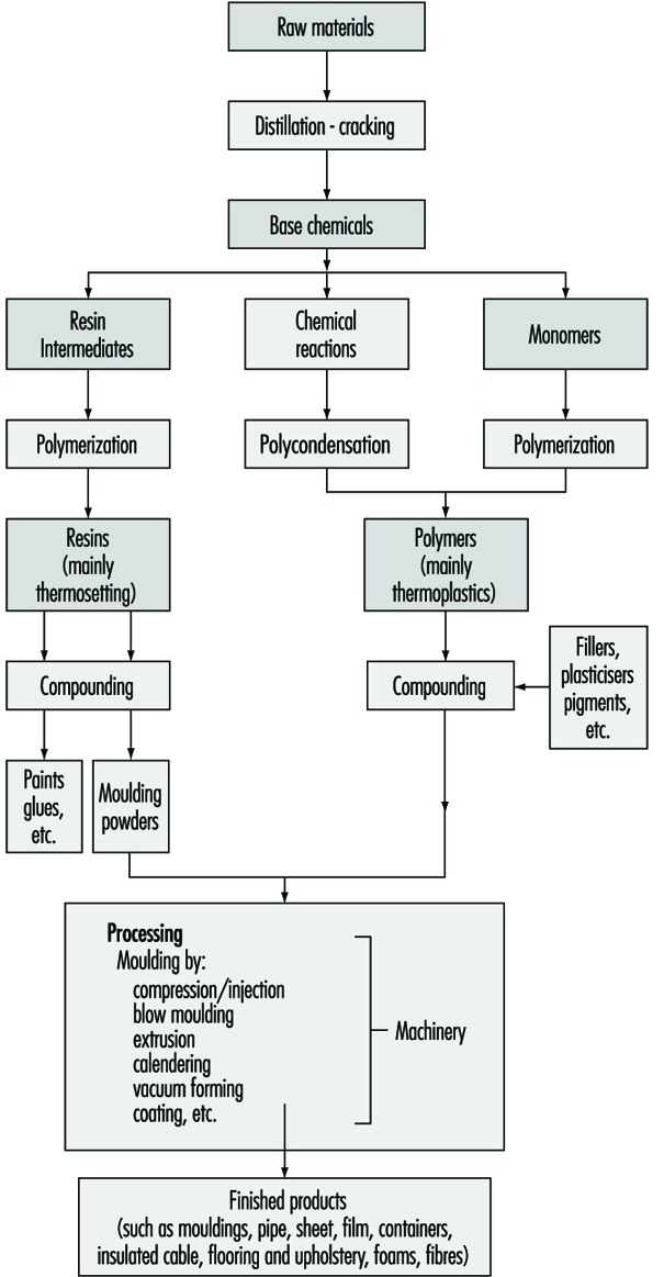
Polymer Manufacturing
Plastics materials fall broadly into two distinct categories: thermoplastics materials, which can be softened repeatedly by the application of heat and thermosetting materials, which undergo a chemical change when heated and shaped and cannot thereafter be reshaped by the application of heat. Several hundred individual polymers can be made with widely differing properties but as few as 20 types constitute about 90% of total world output. Thermoplastics are the largest group and their production is increasing at a higher rate than the thermosetting. In terms of production quantity the most important thermoplastics are high and low density polyethylene and polypropylene (the polyolefins), polyvinyl chloride (PVC) and polystyrene.
Important thermosetting resins are phenol-formaldehyde and urea-formaldehyde, both in the form of resins and moulding powders. Epoxy resins, unsaturated polyesters and polyurethanes are also significant. A smaller volume of “engineering plastics”, for example, polyacetals, polyamides and polycarbonates, have a high value in use in critical applications.
The considerable expansion of the plastics industry in the post Second World War world was greatly facilitated by the broadening of the range of the basic raw materials feeding it; availability and price of raw materials are crucial to any rapidly developing industry. Traditional raw materials could not have provided chemical intermediates in sufficient quantities at an acceptable cost to facilitate the economic commercial production of large-tonnage plastics materials and it was the development of the petrochemicals industry which made growth possible. Petroleum as a raw material is abundantly available, easily transported and handled and was, until the oil crisis of the 1970s, relatively cheap. Therefore, throughout the world, the plastics industry is primarily tied to the use of intermediates obtained from oil cracking and from natural gas. Unconventional feedstocks like biomass and coal have not yet had a major impact on supply to the plastics industry.
The flow chart in figure 2 illustrates the versatility of crude petroleum and natural gas feedstocks as starting points for the important thermosetting and thermoplastics materials. Following the first processes of crude oil distillation, naphtha feedstock is either cracked or reformed to provide useful intermediates. Thus the ethylene produced by the cracking process is of immediate use for the manufacture of polyethylene or for utilization in another process which provides a monomer, vinyl chloride—the basis of PVC. Propylene, which also arises during the cracking process, is used via either the cumene route or the isopropyl alcohol route for the manufacture of acetone needed for polymethylmethacrylate; it is also used in the manufacture of propylene oxide for polyester and polyether resins and again may be polymerized directly to polypropylene. Butenes find use in the manufacture of plasticisers and 1,3-butadiene is utilized directly for synthetic rubber manufacture. Aromatic hydrocarbons such as benzene, toluene and xylene are now widely produced from the derivatives of oil distillation operations, instead of being obtained from coal-coking processes; as the flow chart shows, these are intermediates in the manufacture of important plastics materials and auxiliary products such as plasticizers. The aromatic hydrocarbons are also a starting point for many polymers required in the synthetic fibres industry, some of which are discussed elsewhere in this Encyclopaedia.
Figure 2. Production of raw materials into plastics
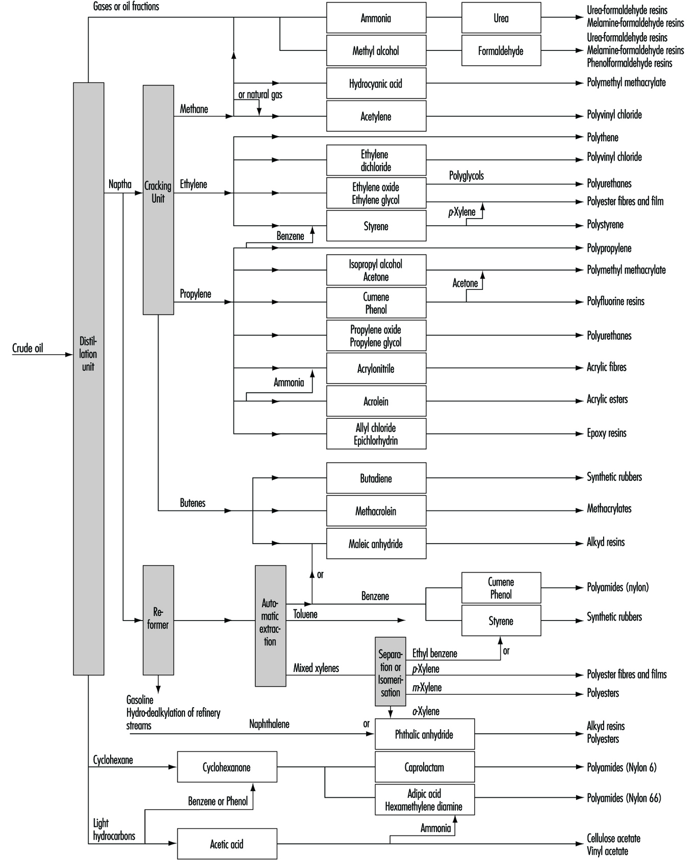
Many widely differing processes contribute to the final production of a finished article made wholly or partly of plastics. Some processes are purely chemical, some involve purely mechanical mixing procedures while others-particularly those towards the lower end of the diagram-involve extensive use of specialized machinery. Some of this machinery resembles that used in rubber, glass, paper and textile industries; the remainder is specific to the plastics industry.
Plastics processing
The plastics processing industry converts bulk polymeric material into finished articles.
Raw materials
The processing section of the plastics industry receives its raw materials for production in the following forms:
- fully compounded polymeric material, in the form of pellets, granules or powder, which is fed directly into the machinery for processing
- uncompounded polymer, in the form of granules or powder, which must be compounded with additives before it is suitable for feeding into to machinery
- polymeric sheet, rod, tube and foil materials which are processed further by the industry
- miscellaneous materials which can be fully polymerized matter in the form of suspensions or emulsions (generally known as latices) or liquids or solids which can polymerise, or substances in an intermediate state between the reactive raw materials and the final polymer. Some of these are liquids and some true solutions of partially polymerised matter in water of controlled acidity (pH) or in organic solvents.
Compounding
The manufacture of compound from polymer entails the mixing of the polymer with additives. Though a great variety of machinery is employed for this purpose, where powders are dealt with, ball mills or high-speed propeller mixers are most common, and where plastic masses are being mixed, kneading machines such as the open rolls or Banbury-type mixers, or extruders themselves are normally employed.
The additives required by the industry are many in number, and range widely in chemical type. Of some 20 classes, the most important are:
- plasticisers—generally esters of low volatility
- antioxidants—organic chemicals to protect against thermal decomposition during processing
- stabilisers—inorganic and organic chemicals to protect against thermal decomposition and against degradation from radiant energy
- lubricants
- fillers—inexpensive matter to confer special properties or to cheapen compositions
- colourants—inorganic or organic matter to colour compounds
- blowing agents—gases or chemicals that emit gases to produce plastic foams.
Conversion processes
All the conversion processes call on the “plastic” phenomenon of polymeric materials and fall into two types. Firstly, those where the polymer is brought by heat to a plastic state in which it is given a mechanical constriction leading to a form which it retains on consolidation and cooling. Secondly, those in which a polymerisable material-which may be partially polymerised-is fully polymerised by the action of heat, or of a catalyst or by both acting together whilst under a mechanical constraint leading to a form which it retains when fully polymerised and cold. Plastics technology has developed to exploit these properties to produce goods with the minimum of human effort and the greatest consistency in physical properties. The following processes are commonly used.
Compression moulding
This consists of heating a plastic material, which can be in the form of granules or powder, in a mould which is held in a press. When the material becomes “plastic” the pressure forces it to conform to the shape of the mould. If the plastic is of the type that hardens on heating, the formed article is removed after a short heating period by opening the press. If the plastic does not harden on heating, cooling must be effected before the press can be opened. Articles made by compression moulding include bottle caps, jar closures, electric plugs and sockets, toilet seats, trays and fancy goods. Compression moulding is also employed to make sheet for subsequent forming in the vacuum forming process or for building into tanks and large containers by welding or by lining existing metal tanks.
Transfer moulding
This is a modification of compression moulding. The thermosetting material is heated in a cavity and then forced by a plunger into the mould, which is physically separate and independently heated from the heating cavity. It is preferred to normal compression moulding when the final article has to carry delicate metallic inserts such as in small electrical switchgear, or when, as in very thick objects, completion of the chemical reaction could not be obtained by normal compression moulding.
Injection moulding
In this process, plastics granules or powders are heated in a cylinder (known as the barrel), which is separate from the mould. The material is heated until it becomes fluid, while it is conveyed through the barrel by a helical screw and then forced into the mould where it cools and hardens. The mould is then opened mechanically and the formed articles are removed (see figure 3). This process is one of the most important in the plastics industry. It has been extensively developed and has become capable of making articles of considerable complexity at very low cost.
Figure 3. An operator removing a polypropylene bowl from an injection-moulding machine.
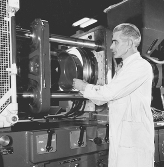
Though transfer and injection moulding are identical in principle, the machinery employed is very different. Transfer moulding is normally restricted to thermosetting materials and injection moulding to thermoplastics.
Extrusion
This is the process in which a machine softens a plastic and forces it through a die which gives it the shape that it retains on cooling. The products of extrusion are tubes or rods which may have cross sections of almost any configuration (see figure 4). Tubes for industrial or domestic purposes are produced in this way, but other articles can be made by subsidiary processes. For example, sachets can be made by cutting tubes and sealing both ends, and bags from thin-walled flexible tubes by cutting and sealing one end.
The process of extrusion has two major types. In one, a flat sheet is produced. This sheet can be converted into useful goods by other processes, such as vacuum forming.
Figure 4. Plastic extrusion: The ribbon is chopped to make pellets for injection moulding machines.
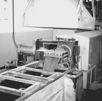
Ray Woodcock
The second is a process in which the extruded tube is formed and when still hot is greatly expanded by a pressure of air maintained inside the tube. This results in a tube which can be several feet in diameter with a very thin wall. On slitting, this tube gives film which is extensively used in the packaging industry for wrapping. Alternatively the tube can be folded flat to give a two-layer sheet which can be used to make simple bags by cutting and sealing. Figure 5 provides an example of appropriate local ventilation on an extrusion process.
Figure 5. Plastic extrusion with local exhaust hood and water bath at extruder head
Ray Woodcock
Calendering
In this process, a plastic is fed to two or more heated rollers and forced into a sheet by passing through a nip between two such rollers and cooling thereafter. Sheet thicker than film is made in this way. Sheet so made is employed in industrial and domestic applications and as the raw material in the manufacture of clothing and inflated goods such as toys (see figure 6).
Figure 6. Canopy hoods to capture hot emissions from warm-up mills on a calender process
Ray Woodcock
Blow moulding
This process can be regarded as a combination of the process of extrusion and thermo-forming. A tube is extruded downwards into an opened mould; as it reaches the bottom the mould is closed round it and the tube expanded by air pressure. Thus the plastic is forced to the sides of the mould and the top and bottom sealed. On cooling, the article is taken from the mould. This process makes hollow articles of which bottles are the most important.
The compression and impact strength of certain plastic products made by blow moulding can be considerably improved by using stretch-blow moulding techniques. This is achieved by producing a pre-form which is subsequently expanded by air pressure and stretched biaxially. This has led to such an improvement in the burst pressure strength of PVC bottles that they are used for carbonated drinks.
Rotational moulding
This process is used for the production of moulded articles by heating and cooling a hollow form which is rotated to enable gravity to distribute finely divided powder or liquid over the inner surface of that form. Articles produced by this method include footballs, dolls and other similar articles.
Film casting
Apart from the extrusion process, films can be formed by extruding a hot polymer on to a highly polished metal drum, or a solution of polymer can be sprayed on to a moving belt.
An important application of certain plastics is the coating of paper. In this, a film of molten plastic is extruded on to paper under conditions in which the plastic adheres to the paper. Board can be coated in the same way. Paper and board so coated are widely used in packaging, and board of this type is used in box making.
Thermo-forming
Under this heading are grouped a number of processes in which a sheet of a plastic material, more often than not thermoplastic, is heated, generally in an oven, and after clamping at the perimeter is forced to a predesigned shape by pressure which may be from mechanically operated rams or by compressed air or steam. For very large articles the “rubbery” hot sheet is manhandled with tongs over formers. Products so made include external light fittings, advertising and directional road signs, baths and other toilet goods and contact lenses.
Vacuum-forming
There are many processes which come under this general heading, all of which are aspects of thermal forming, but they all have in common that a sheet of plastic is heated in a machine above a cavity, around the edge of which it is clamped, and when pliable it is forced by suction into the cavity, where it takes some specific form and cools. In a subsequent operation, the article is trimmed free from the sheet. These processes produce very cheaply thin-walled containers of all types, as well as display and advertising goods, trays and similar articles, and shock-absorbing materials for packing goods such as fancy cakes, soft fruit and cut meat.
Laminating
In all of the various laminating processes, two or more materials in the form of sheets are compressed to give a consolidated sheet or panel of special properties. At one extreme are found decorative laminates made from phenolic and amino resins, at the other complex films used in packaging having, for example, cellulose, polyethylene and metal foil in their constitution.
Resin technology processes
These include plywood manufacture, furniture manufacture and the construction of large and elaborate articles such as car bodies and boat hulls from glass fibre impregnated with polyester or epoxy resins. In all these processes, a liquid resin is caused to consolidate under the action of heat or of a catalyst and so bind together discrete particles or fibres or mechanically weak films or sheets, resulting in a robust panel of rigid construction. These resins can be applied by hand layup techniques such as brushing and dipping or by spraying.
Small objects such as souvenirs and plastic jewellery can also be made by casting, where the liquid resin and catalyst are mixed together and poured into a mould.
Finishing processes
Included under this heading are a number of processes common to many industries, for example the use of paints and adhesives. There are, however, a number of specific techniques used for the welding of plastics. These include the use of solvents such as chlorinated hydrocarbons, methyl ethyl ketone (MEK) and toluene, which are used for bonding together rigid plastic sheets for general fabrication, advertising display stands and similar work. Radiofrequency (RF) radiation utilizes a combination of mechanical pressure and electromagnetic radiation with frequencies generally in the range of 10 to 100 mHz. This method is commonly used for welding together flexible plastic material in the manufacture of wallets, briefcases and children’s push chairs (see the accompanying box). Ultrasonic energies are also used in combination with mechanical pressure for a similar range of work.
RF dielectric heaters and sealers
Radiofrequency (RF) heaters and sealers are used in many industries to heat, melt or cure dielectric materials, such as plastics, rubber and glue which are electrical and thermal insulators and hard to heat using normal methods. RF heaters are commonly used for sealing polyvinyl chloride (e.g., manufacture of plastic products such as raincoats, seat covers and packaging materials); curing of glues used in woodworking; embossing and drying of textiles, paper, leather and plastics; and curing of many materials containing plastic resins.
RF heaters use RF radiation in the frequency range 10 to 100MHz with output power from under 1kW to about 100kW to produce heat. The material to be heated is placed between two electrodes under pressure, and the RF power is applied for periods ranging from a few seconds to about a minute, depending on the use. RF heaters can produce high stray RF electric and magnetic fields in the surrounding environment, especially if the electrodes are unshielded.
Absorption of RF energy by the human body can cause localized and whole body heating, which can have adverse health effects. The body temperature can rise 1 °C or more, which can cause cardiovascular effects such as increased heart rate and cardiac output. Localized effects include eye cataracts, lowered sperm counts in the male reproductive system and teratogenic effects in the developing foetus.
Indirect hazards include RF burns from direct contact with metal parts of the heater which are painful, deep seated and slow to heal; hand numbness; and neurological effects, including carpal tunnel syndrome and peripheral nervous system effects.
Controls
The two basic types of controls that can be used to reduce hazards from RF heaters are work practices and shielding. Shielding, of course, is preferred, but proper maintenance procedures and other work practices can also reduce exposure. Limiting the amount of time the operator is exposed, an administrative control, has also been used.
Proper maintenance or repair procedures are important because failure to properly reinstall shielding, interlocks, cabinet panels and fasteners can result in excessive RF leakage. In addition, electric power to the heater should be disconnected and locked out or tagged out to protect maintenance personnel.
Operator exposure levels can be reduced by keeping the operator’s hands and upper body as far as possible from the RF heater. The operator’s control panels for some automated heaters are positioned at a distance from the heater electrodes by using shuttle trays, turning tables or conveyor belts to feed the heater.
The exposure of both operating and non-operating personnel can be reduced by measuring RF levels. Since RF levels decrease with increasing distance from the heater, an “RF hazard area” can be identified around each heater. Workers can be alerted to not occupy these hazard areas when the RF heater is being operated. Where possible, nonconductive physical barriers should be used to keep people at a safe distance.
Ideally, RF heaters should have a box shield around the RF applicator to contain the RF radiation. The shield and all joints should have high conductivity for the interior electrical currents that will flow in the walls. There should be as few openings in the shield as possible, and they should be as small as is practical for operation. The openings should be directed away from the operator. Currents in the shield can be minimized by having separate conductors inside the cabinet to conduct high currents. The heater should be properly grounded, with the ground wire in the same pipe as the power line. The heater should have proper interlocks to prevent exposure to high voltages and high RF emissions.
It is much easier to incorporate this shielding into new designs of RF heaters by the manufacturer. Retrofitting is more difficult. Box enclosures can be effective. Proper grounding can also often be effective in reducing RF emissions. RF measurements have to be carefully taken afterwards to ensure that RF emissions have actually been reduced. The practice of enclosing the heater in a metal screen-encased room can actually increase exposure if the operator is also in that room, although it does reduce exposures outside the room.
Source: ICNIRP in press.
Hazards and Their Prevention
Polymer manufacturing
The special hazards of the polymers industry relate closely to those of the petrochemicals industry and depend to a large extent on the substances used. The health hazards of individual raw materials are found elsewhere in this Encyclopaedia. The danger of fire and explosion is an important general hazard. Many polymer/resin processes have a fire and explosion risk owing to the nature of the primary raw materials used. If adequate safeguards are not taken there is sometimes a risk during reaction, generally inside partly enclosed buildings, of flammable gases or liquids escaping at temperatures above their flash points. If the pressures involved are very high, provision should be made for adequate venting to the atmosphere. An excessive build-up of pressure due to unexpectedly fast exothermic reactions may occur and the handling of some additives and preparation of some catalysts may add to the explosion or fire risk. The industry has addressed these problems and particularly on the manufacture of phenolic resins has produced detailed guidance notes on plant design engineering and safe operating procedures.
Plastics processing
The plastics processing industry has injury hazards because of the machinery used, fire hazards because of the combustibility of plastics and their powders and health hazards because of the many chemicals used in the industry.
Injuries
The major area for injuries is in the plastics processing sector of the plastics industry. The majority of the plastics conversion processes depend almost entirely upon the use of machinery. As a result the principal hazards are those associated with the use of such machinery, not only during normal operation but also during cleaning, setting and maintenance of the machines.
Compression, transfer, injection and blow moulding machines all have press platens with a locking force of many tonnes per square centimetre. Adequate guarding should be fitted to prevent amputation or crushing injuries. This is generally achieved by enclosing the dangerous parts and by interlocking any movable guards with the machine controls. An interlocking guard should not allow dangerous movement within the guarded area with the guard open and should bring the dangerous parts to rest or reverse the dangerous motion if the guard is opened during the machine operation.
Where there is a severe risk of injury at machinery such as at the platens of moulding machines, and regular access to the danger area, then a higher standard of interlocking is called for. This may be achieved by a second independent interlocking arrangement at the guard to interrupt the power supply and prevent a dangerous motion when it is open.
For processes involving plastic sheet, a common machinery hazard found is in-running traps between rollers or between rollers and the sheet being processed. These occur at tension rollers and haul-off devices at extrusion plant and calenders. Safeguarding may be achieved by using a suitably located trip device, which immediately brings the rollers to rest or reverses the dangerous motion.
Many of the plastics processing machines operate at high temperatures and severe burns may be sustained if parts of the body come into contact with hot metal or plastics. Where practical, such parts should be protected when the temperature exceeds 50 ºC. In addition, blockages which occur on injection moulding machines and extruders can violently free themselves. A safe system of work should be followed when attempting to free frozen plugs of plastic, which should include the use of suitable gloves and face protection.
Most modern machine functions are now controlled by programmed electronic control or computer systems which may also control mechanical take-off devices or are linked with robots. On new machinery there is less need for an operator to approach the danger areas and it follows that safety at machinery should correspondingly improve. There is, however, a greater need for setters and engineers to approach these parts. It is essential therefore that an adequate lockout/tagout programme be instituted before this type of work is carried out, particularly where full protection by the machine safety devices cannot be achieved. In addition adequate back up or emergency systems should be so designed and devised to deal with situations when the programmed control fails for any reason, for example, during the loss of the power supply.
It is important that machines be properly laid out in the workshop with good clear working spaces for each. This assists in maintaining high standards of cleanliness and tidiness. The machines themselves should also be properly maintained and the safety devices should be checked on a routine basis.
Good housekeeping is essential and particular attention should be paid to keeping the floors clean. Without routine cleaning, floors will become badly contaminated from machine oil or spilled plastics granules. Methods of work including safe means of access to areas above floor level should also be considered and provided.
Adequate spacing should also be allowed for the storage of raw materials and finished goods; these areas should be clearly designated.
Plastics are good electrical insulators and, because of this, static charges can build up on machinery on which sheet or film travels. These charges can have a potential high enough to cause a serious accident or act as sources of ignition. Static eliminators should be used to reduce these charges and metal parts properly earthed or grounded.
Increasingly, waste plastics material is being reprocessed using granulators and blending with new stock. Granulators should be totally enclosed to prevent any possibility of reaching the rotors through the discharge and feed openings. The design of the feed openings on large machines should be such as to prevent whole body entry. The rotors operate at high speed and covers should not be removed until they have come to rest. Where interlocking guards are fitted, they should prevent contact with the blades until they have completely stopped.
Fire and explosion hazards
Plastics are combustible materials, although not all polymers support combustion. In finely divided powder form, many can form explosive concentrations in air. Where this is a risk, the powders should be controlled, preferably in an enclosed system, with sufficient relief panels venting at low pressure (about 0.05 bar) to a safe place. Scrupulous cleanliness is essential to prevent accumulations in the workrooms which may become airborne and cause a secondary explosion.
Polymers may be subject to thermal degradation and pyrolysis at temperatures not greatly above normal processing temperatures. Under these circumstances, sufficient pressures may build up in the barrel of an extruder, for example, to eject molten plastic and any solid plug of plastic causing an initial blockage.
Flammable liquids are commonly used in this industry, for example, as paints, adhesives, cleaning agents and in solvent welding. Glass-fibre (polyester) resins also evolve flammable styrene vapours. Stocks of such liquids should be reduced to a minimum in the workroom and stored in a safe place when not in use. Storage areas should include safe places in the open air or a fire resisting store.
Peroxides used in the manufacture of glass reinforced plastics (GRP) resins should be stored separately from flammable liquids and other combustible materials and not subjected to extremes of temperatures since they are explosive when heated.
Health hazards
There are a number of potential health hazards associated with the processing of plastics. The raw plastics are rarely used on their own and appropriate precautions should be taken regarding the additives used in the various formulations. Additives used include lead soaps in PVC and certain organic and cadmium dyestuffs.
There is a significant risk of dermatitis from liquids and powders usually from “reactive chemicals” such as phenol formaldehyde resins (before crosslinking), urethanes and unsaturated polyester resins used in the production of GRP products. Suitable protective clothing should be worn.
It is possible for fumes to be generated from the thermal degradation of polymers during hot processing. Engineering controls can minimize the problem. Particular care, however, must be taken to avoid inhalation of pyrolysis products under adverse conditions, for example, purging of the extruder barrel. Conditions of good LEV may be necessary. Problems have occurred, for example, where operators have been overcome by hydrochloric acid gas and suffered from “polymer fume fever” following overheating of PVC and polytetrafluorethylene (PTFE), respectively. The accompanying box details some chemical decomposition products of plastics.
Table 1. Volatile products of the decomposition of plastics (reference components)*
*Reprinted from BIA 1997, with permission.
In many industrial sectors, plastics are subject to thermal stress. Temperatures range from relatively low values in plastics processing (e.g., 150 to 250 ºC) to extreme cases, e.g., where painted sheet metal or plastic-coated pipes are welded). The question that constantly arises in such cases is whether toxic concentrations of volatile pyrolysis products occur in work areas.
To answer this question, the substances released first need to be determined and then the concentrations need to be measured. While the second step is in principle feasible, it is usually not possible to determine the relevant pyrolysis products in the field. The Berufsgenossenschaftliches Institut für Arbeitssicherheit (BIA) has therefore been examining this problem for years and in the course of many laboratory tests has determined volatile decomposition products for plastics. The test results for the individual types of plastic have been published (Lichtenstein and Quellmalz 1984, 1986a, 1986b, 1986c).
Following is a brief summary of the results to date. This table is intended as an aid for all those faced with the task of measuring hazardous substance concentrations in relevant work areas.The decomposition products listed for the individual plastics may serve as "reference components". It should be remembered, however, that pyrolysis may give rise to highly complex mixtures of substances, their compositions depending on many factors.
The table thus does not claim to be complete where the pyrolysis products listed as reference components are concerned (all determined in laboratory experiments). The occurrence of other substances with potential health risks cannot be ruled out. It is practically impossible to completely record all substances that occur.
|
Plastic |
Abbreviation |
Volatile substances |
|
Polyoxymethylene |
POM |
Formaldehyde |
|
Epoxy resins based on |
Phenol |
|
|
Chloroprene rubber |
CR |
Chloroprene(2-chlorobuta-1,3-diene), |
|
Polystyrene |
PS |
Styrene |
|
Acrylonitrile-butadiene-styrene- |
ABS |
Styrene, 1,3-butadiene, acrylonitrile |
|
Styrene-acrylonitrile copolymer |
SAN |
Acrylonitrile, styrene |
|
Polycarbonates |
PC |
Phenol |
|
Polyvinyl chloride |
PVC |
Hydrogen chloride, plasticisers |
|
Polyamide 6 |
PA 6 |
e-caprolactam |
|
Polyamide 66 |
PA 66 |
Cyclopentanone, |
|
Polyethylene |
HDPE, LDPE |
Unsaturated aliphatic hydrocarbons, |
|
Polytetrafluoroethylene |
PTFE |
Perfluorinated unsaturated |
|
Polymethyl methacrylate |
PMMA |
Methyl methacrylate |
|
Polyurethane |
PUR |
Depending on the type, widely varying |
|
Polypropylene |
PP |
Unsaturated and saturated aliphatic |
|
Polybutyle enterephthalate |
PBTP |
1,3-butadiene, benzene |
|
Polyacrylonitrile |
PAN |
Acrylonitrile, hydrogen cyanide2 |
|
Cellulose acetate |
CA |
Acetic acid |
Norbert Lichtenstein
1 Use is discontinuing.
2 Could not be detected with the analytical technique used (GC/MS) but is known from the literature.
There is also a danger of inhalation of toxic vapours from certain thermoset resins. Inhalation of isocyanates used with polyurethane resins can lead to chemical pneumonia and severe asthma and, once sensitized, persons should be transferred to alternative work. A similar problem exists with formaldehyde resins. In both these examples, a high standard of LEV is necessary. In the manufacture of GRP articles, significant quantities of styrene vapour is given off and this work must be done in conditions of good general ventilation in the workroom.
There are also certain hazards which are common to a number of industries. These include the use of solvents for dilution or for purposes mentioned previously. Chlorinated hydrocarbons are commonly used for cleaning and bonding and without adequate exhaust ventilation persons may well suffer from narcosis.
Waste disposal of plastics by burning should be done under carefully controlled conditions; for example, PTFE and urethanes should be in an area where the fumes are vented to a safe place.
Very high noise levels are generally obtained during the use of granulators, which may well lead to hearing loss to the operators and persons working nearby. This hazard can be confined by separating this equipment from other working areas. Preferably the noise levels should be reduced at source. This has successfully been achieved by coating the granulator with sound deadening material and fitting baffles at the feed opening. There may also be a hazard to hearing created by audible sound produced from ultrasonic welding machines as a normal accompaniment of the ultrasonic energies. Suitable enclosures can be designed to reduce the received noise levels and can be interlocked to prevent a mechanical hazard. As a minimum standard, persons working in areas of high noise levels should wear suitable hearing protection and there should be a suitable hearing conservation programme, including audiometric testing and training.
Burns are also a hazard. Some additives and catalysts for plastics production and processing can be highly reactive on contact with air and water and may readily cause chemical burns. Wherever molten thermoplastics are being handled or transported there is the danger of splashes of hot material and consequent burns and scalds. The severity of these burns may be increased by the tendency of hot thermoplastics, like hot wax, to adhere to the skin.
Organic peroxides are irritants and may cause blindness if splashed in the eye. Suitable eye protection should be worn.
Biotechnology Industry
Evolution and Profile
Biotechnology can be defined as the application of biological systems to technical and industrial processes. It encompasses both traditional and genetically engineered organisms. Traditional biotechnology is the result of classic hybridization, mating or crossing of various organisms to create new organisms that have been used for centuries to produce bread, beer, cheese, soya, saki, vitamins, hybrid plants and antibiotics. More recently, various organisms have also been used to treat waste water, human sewage and industrial toxic wastes.
Modern biotechnology combines the principles of chemistry and biological sciences (molecular and cellular biology, genetics, immunology) with technological disciplines (engineering, computer science) to produce goods and services and for environmental management. Modern biotechnology utilizes restriction enzymes to cut and paste genetic information, DNA, from one organism to another outside living cells. The composite DNA is then reintroduced into host cells to determine whether the desired trait is expressed. The resulting cell is called an engineered clone, a recombinant or a genetically manipulated organism (GMO). The “modern” biotechnology industry was born in 1961-1965 with the breaking of the genetic code and has grown dramatically since the first successful DNA cloning experiments in 1972.
Since the early 1970s, scientists have understood that genetic engineering is an extremely powerful and promising technology, but that there are potentially serious risks to consider. As early as on 1974, scientists called for a worldwide moratorium on specific types of experiments in order to assess the risks and to devise appropriate guidelines for avoiding biological and ecological hazards (Committee on Recombinant DNA Molecules, National Research Council, National Academy of Sciences 1974). Some of the concerns expressed involved the potential “escape of vectors which could initiate an irreversible process, with a potential for creating problems many times greater than those arising from the multitude of genetic recombinations that occur spontaneously in nature”. There were concerns that “microorganisms with transplanted genes could prove hazardous to man or other forms of life. Harm could result if the altered host cell has a competitive advantage that would foster its survival in some niche within the ecosystem” (NIH 1976). It was also well understood that laboratory workers would be the “canaries in the coal mine” and some attempt should be made to protect the workers as well as the environment from the unknown and potentially serious hazards.
An international conference in Asilomar, California, was held in February 1975. Its report contained the first consensus guidelines based on biologic and physical containment strategies for controlling potential hazards envisioned from the new technology. Certain experiments were judged to pose such serious potential dangers that the conference recommended against their being conducted at that time (NIH 1976). The following work was originally banned:
- work with DNA from pathogenic organisms and oncogenes
- forming recombinants that incorporate toxin genes
- work which might extend the host range of plant pathogens
- introduction of drug resistance genes into organisms not known to acquire them naturally and where treatment would be compromised
- deliberate release into the environment (Freifelder 1978).
In the United States the first National Institutes of Health Guidelines (NIHG) were published in 1976, replacing the Asilomar guidelines. These NIHG allowed research to proceed by rating experiments by hazard classes based on the risks associated with host cell, vector systems which transport genes into the cells and gene inserts, thereby allowing or restricting the conduct of the experiments based on risk assessment. The basic premise of the NIHG—to provide for worker protection, and by extension, community safety—remains in place today (NIH 1996). The NIHG are updated regularly and they have evolved to be a widely accepted standard of practice for biotechnology in the US. Compliance is required from institutions receiving federal funding, as well as by many local city or town ordinances. The NIHG provides one basis for regulations in other countries around the world, including Switzerland (SCBS 1995) and Japan (National Institute of Health 1996).
Since 1976, the NIHG have been expanded to incorporate containment and approval considerations for new technologies including large scale production facilities and plant, animal and human somatic gene therapy proposals. Some of the originally banned experiments are now allowed with specific approval from NIH or with specific containment practices.
In 1986 the US Office of Science and Technology Policy (OSTP) published its Coordinated Framework for Biotechnology Regulation. It addressed the underlying policy question of whether existing regulations were adequate to evaluate products derived from the new technologies and whether the review processes for research were sufficient to protect the public and the environment. The US regulatory and research agencies (Environmental Protection Agency (EPA), Food and Drug Administration (FDA), Occupational Safety and Health Administration (OSHA), NIH, US Department of Agriculture (USDA) and National Science Foundation (NSF)) agreed to regulate products, not processes, and that new, special regulations were not necessary to protect workers, the public or the environment. The policy was established to operate regulatory programmes in an integrated and coordinated fashion, minimizing overlap, and, to the extent possible, responsibility for product approval would lie with one agency. The agencies would coordinate efforts by adopting consistent definitions and by using scientific reviews (risk assessments) of comparable scientific rigor (OSHA 1984; OSTP 1986).
The NIHG and Coordinated Framework have provided an appropriate degree of objective scientific discussion and public participation, which has resulted in the growth of US biotechnology into a multibillion dollar industry. Prior to 1970, there were fewer than 100 companies involved in all aspects of modern biotechnology. By 1977, another 125 firms joined the ranks; by 1983 an additional 381 companies brought the level of private capital investment to more than $1 billion. By 1994 the industry had grown to more than 1,230 companies (Massachusetts Biotechnology Council Community Relations Committee 1993), and market capitalization is more than $6 billion.
Employment in US biotechnology companies in 1980 was about 700 people; in 1994 roughly 1,300 companies employed more than 100,000 workers (Massachusetts Biotechnology Council Community Relations Committee 1993). In addition, there is an entire support industry which provides supplies (chemicals, media components, cell lines), equipment, instrumentation and services (cell banking, validation, calibration) necessary to ensure the integrity of the research and production.
Throughout the world there has been a great level of concern and scepticism about the safety of the science and of its products. The Council of the European Communities (Parliament of the European Communities 1987) developed directives to protect workers from the risks associated with exposure to biologicals (Council of the European Communities 1990a) and to place environmental controls on experimental and commercial activities including deliberate release. “Release” includes marketing products using GMOs (Council of the European Communities 1990b; Van Houten and Flemming 1993). Standards and guidelines pertaining to biotechnology products within international and multilateral organizations such as World Health Organization (WHO), International Standards Organization (ISO), Commission of the European Community, Food and Agriculture Organization (FAO) and Microbial Strains Data Network have been developed (OSTP 1986).
The modern biotechnology industry can be considered in terms of four major industry sectors, each having laboratory, field and/or clinical research and development (R&D) supporting the actual production of goods and services.
- biomedical-pharmaceuticals, biologics and medical device products
- agricultural-foods, transgenic fish and animals, disease resistant and pest resistant plants
- genetically enhanced industrial products such as citric acid, butanol, acetone, ethanol and detergent enzymes (see table 1)
- environmental-waste water treatment, decontamination of industrial wastes.
Table 1. Microorganisms of industrial importance
|
Name |
Host organism |
Uses |
|
Acetobacter aceti |
Aerobic bacterium |
Ferments fruit |
|
Aspirgillus niger |
Asexual fungus |
Degrades organic matter |
|
Aspirgillus oryzae |
Asexual fungus |
Used in production of miso, soy sauce and sake |
|
Bacillis licheniformis |
Bacterium |
Industrial chemicals and enzymes |
|
Bacillis subtilis |
Bacterium |
Chemicals, enzymes, source of single-cell protein for human consumption in Asia |
|
Chinese hampster ovary cells (CHO)* |
Mammalian cell culture |
Manufacturing of biopharmaceuticals |
|
Clostridium acetobutylicum |
Bacterium |
Butanol, acetone production |
|
Escherichia coli K-12* |
Bacterial strain |
Cloning for fermentation, production of pharmaceuticals and biologics |
|
Penicillium roqueforti |
Asexual fungus |
Blue cheese production |
|
Saccharomyces cerevisiae* |
Yeast |
Cloning for beer production |
|
Saccharomyces uvarum* |
Yeast |
Cloning for alcoholic beverages and industrial alcohol production |
* Important to modern biotechnology.
Biotechnology Workers
Biotechnology begins in the research laboratory and is a multidisciplinary science. Molecular and cellular biologists, immunologists, geneticists, protein and peptide chemists, biochemists and biochemical engineers are most directly exposed to the real and potential hazards of recombinant DNA (rDNA) technology. Other workers who may be exposed less directly to rDNA biohazards include service and support staff such as ventilation and refrigeration technicians, calibration service providers and housekeeping staff. In a recent survey of health and safety practitioners in the industry, it was found that the directly and indirectly exposed workers comprise about 30 to 40% of the total workforce in typical commercial biotechnology companies (Lee and Ryan 1996). Biotechnology research is not limited to “industry”; it is conducted in the academic, medical and government institutions as well.
Biotechnology laboratory workers are exposed to a wide variety of hazardous and toxic chemicals, to recombinant and non-recombinant or “wild type” biological hazards, human bloodborne pathogens and zoonotic illnesses as well as radioactive materials used in labelling experiments. In addition, musculoskeletal disorders and repetitive strain injuries are becoming more widely recognized as potential hazards to research workers due to extensive use of computers and manual micropipettors.
Biotechnology manufacturing operators are also exposed to hazardous chemicals, but not the variety one sees in the research setting. Depending on the product and the process, there may be exposure to radionuclides in manufacturing. At even the lowest biohazard level, biotechnology manufacturing processes are closed systems and potential for exposure to the recombinant cultures is low, except in the case of accidents. In biomedical production facilities, application of current good manufacturing practices complements biosafety guidelines to protect workers on the plant floor. The main hazards to manufacturing workers in good large-scale practice (GLSP) operations involving non-hazardous recombinant organisms include traumatic musculoskeletal injuries (e.g., back strains and pain), thermal burns from steam lines and chemical burns from acids and caustics (phosphoric acid, sodium and potassium hydroxide) used in the process.
Health care workers including clinical laboratory technicians are exposed to gene therapy vectors, excreta and laboratory specimens during the administration of drugs and care of patients enrolled in these experimental procedures. Housekeepers may also be exposed. Worker and environmental protection are two mandatory experimental points to consider in making application to NIH for human gene therapy experiments (NIH 1996).
Agricultural workers may have gross exposure to recombinant products, plants or animals during the application of pesticides, planting, harvesting and processing. Independent of the potential biohazard risk from exposure to genetically altered plants and animals, the traditional physical hazards involving farm equipment and animal husbandry are also present. Engineering controls, PPE, training and medical supervision are used as appropriate to the anticipated risks (Legaspi and Zenz 1994; Pratt and May 1994). PPE including jump suits, respirators, utility gloves, goggles or hoods are important for worker safety during application, growth and harvesting of the genetically modified plants or soil organisms.
Processes and Hazards
In the biotechnology process in the biomedical sector cells or organisms, modified in specific ways to yield desired products, are cultivated in monoculture bioreactors. In mammalian cell culture, the protein product is secreted from the cells into the surrounding nutrient medium, and a variety of chemical separation methods (size or affinity chromatography, electrophoresis) may be used to capture and purify the product. Where Escherichia coli host organisms are used in fermentations, the desired product is produced within the cell membrane and the cells must be physically ruptured in order to harvest the product. Endotoxin exposure is a potential hazard of this process. Often antibiotics are added to the production media to enhance production of the desired product or maintain selective pressure on otherwise unstable genetic production elements (plasmids). Allergic sensitivities to these materials are possible. In general, these are aerosol exposure risks.
Leaks and releases of aerosols are anticipated and potential exposure is controlled in several ways. Penetrations into the reactor vessels are necessary for providing nutrients and oxygen, for off-gassing carbon dioxide (CO2) and for monitoring and controlling the system. Each penetration must be sealed or filtered (0.2 micron) to prevent contamination of the culture. The exhaust gas filtration also protects workers and environment in the work area from aerosols generated during the culture or fermentation. Depending on the biohazard potential of the system, validated biological inactivation of liquid effluents (usually by heat, steam or chemical methods) is standard practice. Other potential hazards in biotech manufacturing are similar to those in other industries: noise, mechanical guarding, steam/heat burns, contact with corrosives and so on.
Enzymes and industrial fermentation are covered elsewhere in this Encyclopaedia and involve the processes, hazards and controls that are similar for genetically engineered production systems.
Traditional agriculture depends on strain development that utilizes traditional crossing of related plant species. The great advantage of genetically engineering plants is that the time between generations and the number of crosses needed to obtain the desired trait is greatly reduced. Also the currently unpopular reliance on chemical pesticides and fertilizers (which contribute to runoff pollution) is favouring a technology which will potentially make these applications unnecessary.
Plant biotechnology involves choosing a genetically pliable and/ or financially significant plant species for modifications. Since plant cells have tough, cellulose cell walls, methods used to transfer DNA into plant cells differ from those used for bacteria and mammalian cell lines in the biomedical sector. There are two primary methods used for introducing foreign engineered DNA into plant cells (Watrud, Metz and Fishoff 1996):
- a particle gun shoots DNA into the cell of interest
- a disarmed, nontumorigenic Agrobacterium tumefaciens virus introduces gene cassettes into the cell’s genetic material.
Wild-type Agrobacterium tumefaciens is a natural plant pathogen which causes crown gall tumours in injured plants. These disarmed, engineered vector strains do not cause plant tumour formation.
After transformation by either method, plant cells are diluted, plated and grown on selective tissue culture media for a relatively long (compared to bacterial growth rates) period in plant growth chambers or incubators. Plants regenerated from the treated tissue are transplanted to soil in enclosed growth chambers for further growth. After reaching the appropriate age they are examined for expression of the desired traits and then grown in greenhouses. Several generations of greenhouse experiments are needed to evaluate the genetic stability of the trait of interest and to generate needed seed stock for further study. Environmental impact data is also gathered during this phase of the work and submitted with proposals to regulatory agencies for open field trial release approval.
Controls: The United States Example
The NIHG (NIH 1996) describe a systematic approach to preventing both worker exposure to and environmental release of recombinant organisms. Each institution (e.g., university, hospital or commercial laboratory) is responsible for conducting rDNA research safely and in compliance with the NIHG. This is accomplished through an administrative system which defines responsibilities and requires comprehensive risk assessments by knowledgeable scientists and biosafety officers, implementation of exposure controls, medical surveillance programmes and emergency planning. An Institutional Biosafety Committee (IBC) provides the mechanisms for experiment review and approval within the institution. In some cases, approval of NIH Recombinant Advisory Committee (RAC) itself is required.
The degree of control depends on the severity of the risk and is described in terms of Biosafety Level (BL) designations 1-4; BL1 being the least restrictive and BL4 the most. Containment guidelines are given for research, large scale (greater than 10 litres of culture) R&D, large scale production and animal and plant experiments at both large and small scale.
Appendix G of the NIHG (NIH 1996) describes physical containment at the laboratory scale. BL1 is appropriate for work with agents of no known or of minimal potential hazard to laboratory personnel or the environment. The laboratory is not separated from the general traffic patterns in the building. Work is conducted on the open benchtops. No special containment devices are required or used. Laboratory personnel are trained in laboratory procedures and supervised by a scientist with general training in microbiology or a related science.
BL2 is suitable for work involving agents of moderate potential hazard to personnel and the environment. Access to the laboratory is limited when work is being conducted, workers have specific training in handling pathogenic agents and are directed by competent scientists, and work which creates aerosols is conducted in biological safety cabinets or other containment equipment. This work may require medical surveillance or vaccinations as appropriate and determined by the IBC.
BL3 is applicable when work is conducted with indigenous or exotic agents which may cause serious or potentially lethal disease as a result of exposure by inhalation. Workers have specific training and are supervised by competent scientists who are experienced in working with handling these hazardous agents. All procedures are done under containment conditions requiring special engineering and PPE.
BL4 is reserved for the most dangerous and exotic agents that pose a high individual and community risk of life-threatening disease. There are only a few BL4 laboratories in the world.
Appendix K addresses physical containment for research or production activities in volumes greater than 10 l (large scale). As in the small-scale guidelines, there is a hierarchy of containment requirements from lowest to highest hazard potential: GLSP to BL3-Large-Scale (BL3-LS).
The NIHG, Appendix P, covers work with plants at bench level, growth chamber and greenhouse scale. As the introduction notes: “The principal purpose of plant containment is to avoid the unintentional transmission of a recombinant DNA-containing plant genome, including nuclear or organelle hereditary material or release of recombinant DNA derived organisms associated with plants. In general these organisms pose no threat to human health or higher animals, unless deliberately modified for that purpose. However, the inadvertent spread of a serious pathogen from a greenhouse to a local agricultural crop or the unintentional introduction and establishment of an organism in a new ecosystem is possible” (NIH 1996). In the United States, the EPA and the USDA’s Animal and Plant Health Inspection Service (APHIS) are jointly responsible for risk assessment and for reviewing the data generated prior to giving approval for field release testing (EPA 1996; Foudin and Gay 1995). Issues such as persistence and spread in water, air and soil, by insect and animal species, the presence of other similar crops in the area, environmental stability (frost or heat sensitivity) and competition with native species are evaluated-often first in the greenhouse (Liberman et al. 1996).
Plant containment levels for facilities and practices also range from BL1 to BL4. Typical BL1 experiments involve self-cloning. BL2 may involve transfer of traits from a pathogen to a host plant. BL3 might involve toxin expression or environmentally hazardous agents. Worker protection is achieved in the various levels by PPE and engineering controls such as greenhouses and headhouses with directional airflow and high efficiency particulate air filters (HEPA) to prevent pollen release. Depending on the risk, environmental and community protection from potentially hazardous agents can be achieved by biological controls. Examples are a temperature sensitive trait, drug sensitivity trait or nutritional requirement not present in nature.
As scientific knowledge increased and technology advanced, it was expected that the NIHG would need review and revision. Over the last 20 years, the RAC has met to consider and approve proposals for changes. For example, the NIHG no longer issue blanket prohibitions on deliberate release of genetically engineered organisms; agricultural products field trial releases and human gene therapy experiments are allowed in appropriate circumstances and after suitable risk assessment. One very significant amendment to the NIHG was the creation of the GLSP containment category. It relaxed the containment requirements for “non-pathogenic, non-toxigenic recombinant strains derived from host organisms that have an extended history of safe large scale use, or which have built in environmental limitations that permit optimum growth in the large scale setting but limited survival without adverse consequences in the environment” (NIH 1991). This mechanism has allowed the technology to progress while still considering safety needs.
Controls: The European Community Example
In April 1990 the European Community (EC) enacted two Directives on the contained use and deliberate release into the environment of GMOs. Both Directives require Member States to ensure that all appropriate measures are taken to avoid adverse effects on human health or the environment, in particular by making the user assess all relevant risks in advance. In Germany, the Genetic Technology Act was passed in 1990 partially in response to the EC Directives, but also to respond to a need for legal authority to construct a trial operation recombinant insulin production facility (Reutsch and Broderick 1996). In Switzerland, the regulations are based on the US NIHG, Council directives of the EC and the German law on gene technology. The Swiss require annual registration and updates of experiments to the government. In general, the rDNA standards in Europe are more restrictive than in the US, and this has contributed to many European pharmaceutical firms moving rDNA research from their home countries. However, the Swiss regulations allow a Large Scale Safety Level 4 category, which is not permitted under the NIHG (SCBS 1995).
Products of Biotechnology
Some of the biological and pharmaceutical products which have been successfully made by recombinant DNA biotechnologies include: human insulin; human growth hormone; hepatitis vaccines; alpha-interferon; beta-interferon; gamma-interferon; Granulocyte colony stimulating factor; tissue plasminogen activator; Granulocyte-macrophage colony stimulating factor; IL2; Erythropoietin; Crymax, an insecticide product for the control of caterpillars in vegetable; tree nut and vine crops; Flavr Savr (TM) tomato; Chymogen, an enzyme that makes cheese; ATIII (antithrombin III), derived from transgenic goat milk used to prevent blood clots in surgery; BST and PST (bovine and porcine somatotropin) used to boost milk and meat production.
Health Problems and Disease Patterns
There are five main health hazards from exposure to microorganisms or their products in industrial scale biotechnology:
- infection
- reaction to endotoxin
- allergy to the microorganisms
- allergic reaction to a product
- toxic reaction to a product.
Infection is unlikely since non-pathogens are used in most industrial processes. However, it is possible that microorganisms considered to be harmless such as Pseudomonas and Aspergillus species may cause infection in immunocompromised individuals (Bennett 1990). Exposure to endotoxin, a component of the lippopolysaccharide layer of the cell wall of all gram negative bacteria, at concentrations greater than about 300 ng/m3 causes transient flu-like symptoms (Balzer 1994). Workers in many industries including traditional agriculture and biotechnology have experienced the effects of endotoxin exposure. Allergic reactions to the microorganism or product also occur in many industries. Occupational asthma has been diagnosed in the biotechnology industry for a wide range of microorganisms and products including Aspergillus niger, Penicillium spp. and proteases; some companies have noted incidences in greater than 12% of the workforce. Toxic reactions can be as varied as the organisms and products. Exposure to antibiotics has been shown to cause shifts in microbial flora in the gut. Fungi are known to be capable of producing toxins and carcinogens under certain growth conditions (Bennett 1990).
To address concern that exposed workers would be the first to develop any potential adverse health effects from the new technology, medical surveillance of rDNA workers has been a part of the NIHG since their beginning. Institutional Biosafety Committees, in consultation with the occupational health physician, are charged with determining, on a project by project basis, what medical surveillance is appropriate. Depending on the identity of the specific agent, the nature of the biological hazard, the potential routes of exposure and availability of vaccines, the components of the medical surveillance programme might include pre-placement physical, periodic follow-up exams, specific vaccines, specific allergy and illness evaluations, pre-exposure sera and epidemiological surveys.
Bennett (1990) believes it is unlikely that genetically modified microorganisms will pose more of an infection or allergic risk than the original organism, but there could be additional risks from the novel product, or the rDNA. A recent report notes the expression of a brazil-nut allergen in transgenic soybeans may cause unexpected health effects among workers and consumers (Nordlee et al. 1996). Other novel hazards could be the use of animal cell lines containing unknown or undetected oncogenes or viruses potentially harmful to humans.
It is important to note the early fears concerning the creation of genetically dangerous mutant species or super-toxins have not materialized. The WHO found that biotechnology poses no risks that are different from other processing industries (Miller 1983), and, according to Liberman, Ducatman and Fink (1990), “the current consensus is that the potential risks of rDNA were overstated initially and that the hazards associated with this research are similar to those associated with the organism, vector, DNA, solvents and physical apparatus being used”. They conclude that engineered organisms are bound to have hazards; however, containment can be defined to minimize exposure.
It is very difficult to identify occupational exposures specific to the biotechnology industry. “Biotechnology” is not a separate industry with a distinguishing Standard Industrial Classification (SIC) code; rather, it is viewed as a process or set of tools used in many industrial applications. Consequently, when accidents and exposures are reported, the data on cases involving biotechnology workers are included among data on all others which occur in the host industry sector (e.g., agriculture, pharmaceutical industry or health care). Furthermore, laboratory incidents and accidents are known to be under reported.
Few illnesses specifically due to genetically altered DNA have been reported; however, they are not unknown. At least one documented local infection and seroconversion was reported when a worker suffered a needle stick contaminated with a recombinant vaccinia vector (Openshaw et al. 1991).
Policy Issues
In the 1980s the first products of biotechnology emerged in the US and Europe. Genetically engineered insulin was approved for use in 1982, as was a genetically engineered vaccine against the pig disease “scours” (Sattelle 1991). Recombinant bovine somatotropin (BST) has been shown to increase a cow’s milk production and the weight of beef cattle. Concerns were raised about public health and product safety and whether existing regulations were adequate to address these concerns in all the different areas where products of biotechnology could be marketed. The NIHG provide protection of workers and the environment during research and development stages. Product safety and efficacy is not a NIHG responsibility. In the US, through the Coordinated Framework, potential risks of the products of biotechnology are evaluated by the most appropriate agency (FDA, EPA or USDA).
The debate over safety of genetic engineering and the products of biotechnology continues (Thomas and Myers 1993), especially with respect to agricultural applications and foods for human consumption. Consumers in some areas want produce labelled to identify which are the traditional hybrids and which are derived from biotechnology. Certain manufacturers of dairy products refuse to use milk from cows receiving BST. It is banned in some countries (e.g., Switzerland). The FDA has deemed the products to be safe, but there are also economic and social issues which may not be acceptable to the public. BST may indeed create a competitive disadvantage for smaller farms, most of which are family run. Unlike medical applications where there may be no alternative to genetically engineered treatment, when traditional foods are available and plentiful, the public is in favour of traditional hybridization over recombinant food. However, harsh environments and the current worldwide food shortage may change this attitude.
Newer applications of the technology to human health and inherited diseases have revived the concerns and created new ethical and social issues. The Human Genome Project, which began in the early 1980s, will produce a physical and genetic map of human genetic material. This map will provide researchers with information to compare “healthy or normal” and “diseased” gene expression to better understand, predict and point to cures for the basic genetic defects. Human Genome technologies have produced new diagnostic tests for Huntington’s Disease, cystic fibrosis and breast and colon cancers. Somatic human gene therapy is expected to correct or improve treatments for inherited diseases. DNA “fingerprinting” by restriction fragment polymorphism mapping of genetic material is used as forensic evidence in cases of rape, kidnapping and homicide. It can be used to prove (or, technically, disprove) paternity. It can also be used in more controversial areas, such as for assessing chances of developing cancer and heart disease for insurance coverage and preventative treatments or as evidence in war crimes tribunals and as genetic “dogtags” in the military.
Though technically feasible, work on human germ-line experiments (transmissible from generation to generation) have not been considered for approval in the US due to the serious social and ethical considerations. However, public hearings are planned in the US to reopen the discussion of human germ-line therapy and the desirable trait enhancements not associated with diseases.
Finally, in addition to safety, social and ethical issues, legal theories about ownership of genes and DNA and liability for use or misuse are still evolving.
Long-term implications of environmental release of various agents need to be followed. New biological containment and host range issues will come up for work which is carefully and appropriately controlled in the laboratory environment, but for which all environmental possibilities are not known. Developing countries, where adequate scientific expertise and or regulatory agencies may not exist, may find themselves either unwilling or unable to take on the assessment of risk for their particular environment. This could lead to unnecessary restrictions or an imprudent “open-door” policy, either of which could prove damaging to the long-term benefit of the country (Ho 1996).
In addition, caution is important when introducing engineered agricultural agents into novel environments where frost or other natural containment pressures are not present. Will indigenous populations or natural exchangers of genetic information mate with recombinant agents in the wild resulting in transfer of engineered traits? Would these traits prove harmful in other agents? What would be the effect to the treatment administrators? Will immune reactions limit spread? Are engineered live agents capable of crossing species barriers? Do they persist in the environment of deserts, mountains, plain and cities?
Summary
Modern biotechnology in the United States has developed under consensus guidelines and local ordinance since the early 1970s. Careful scrutiny has shown no unexpected, uncontrollable traits expressed by a recombinant organism. It is a useful technology, without which many medical improvements based on natural therapeutic proteins would not have been possible. In many developed countries biotechnology is a major economic force and an entire industry has grown around the biotechnology revolution.
Medical issues for biotechnology workers are related to the specific host, vector and DNA risks and the physical operations performed. So far worker illness has been preventable by engineering, work practice, vaccines and biological containment controls specific to the risk as assessed on a case by case basis. And the administrative structure is in place to do prospective risk assessments for each new experimental protocol. Whether this safety track record continues into the environmental release of viable materials arena is a matter of continued evaluation of the potential environmental risks-persistence, spread, natural exchangers, characteristics of the host cell, host range specificity for transfer agents used, nature of the inserted gene and so on. This is important to consider for all possible environments and species affected in order to minimize surprises that nature often presents.
Pyrotechnics Industry
Adapted from 3rd edition, “Encyclopaedia of Occupational Health and Safety”.
The pyrotechnics industry may be defined as the manufacture of pyrotechnic articles (fireworks) for entertainment, for technical and military use in signalling and illumination, for use as pesticides and for various other purposes. These articles contain pyrotechnic substances made up of powders or paste compositions which are shaped, compacted or compressed as required. When they are ignited, the energy they contain is released to give specific effects, such as illumination, detonation, whistling, screaming, smoke formation, smouldering, propulsion, ignition, priming, shooting and disintegration. The most important pyrotechnic substance is still black powder (gunpowder, consisting of charcoal, sulphur and potassium nitrate), which may be used loose for detonation, compacted for propulsion or shooting, or buffered with wood charcoal as a primer.
Processes
Raw materials used in the manufacture of pyrotechnics must be very pure, free from all mechanical impurities and (above all) free from acid ingredients. This also applies to subsidiary materials such as paper, pasteboard and glue. Table 1 lists common raw materials used in pyrotechnics manufacture.
Table 1. Raw materials used in the manufacture of pyrotechnics
|
Products |
Raw materials |
|
Explosives |
Nitrocellulose (collodion wool), silver fulminate, black powder |
|
Combustible materials |
Acaroid resin, dextrine, gallic acid, gum arabic, wood, charcoal, |
|
Oxidizing materials |
Potassium chlorate, barium chlorate, potassium, perchlorate, barium |
|
Flame-tinting materials |
Barium carbonate (green), cryolite (yellow), copper, ammonium |
|
Inert materials |
Glyceryl tristearate, paraffin, diatomaceous earth, lime, chalk. |
After being dried, ground and sifted, the raw materials are weighed and mixed in a special building. Formerly they were always mixed by hand but in modern plants mechanical mixers are often used. After mixing, the substances should be kept in special storage buildings to avoid accumulations in workrooms. Only the quantities required for the actual processing operations should be taken from these buildings into the workrooms.
The cases for pyrotechnic articles may be of paper, pasteboard, synthetic material or metal. The method of packing varies. For example, for detonation the composition is poured loose into a case and sealed, whereas for propulsion, illumination, screaming or whistling it is poured loose into the case and then compacted or compressed and sealed.
Compacting or compressing formerly was done by blows from a mallet on a wooden “setting-down” tool, but this method is rarely employed in modern facilities; hydraulic presses or rotary lozenge presses are used instead. Hydraulic presses enable the composition to be compressed simultaneously in a number of cases.
Illumination substances are often shaped when wet to form stars, which are then dried and put into cases for rockets, bombs and so on. Substances made by a wet process must be well dried or they may ignite spontaneously.
Since many pyrotechnic substances are difficult to ignite when compressed, the pyrotechnic articles concerned are provided with an intermediate or priming ingredient to ensure ignition; the case is then sealed. The article is ignited from the outside by a quick-match, a fuse, a scraper or sometimes by a percussion cap.
Hazards
The most important hazards in pyrotechnics are clearly fire and explosion. Because of the small number of machines involved, mechanical hazards are less important; they are similar to those in other industries.
The sensitivity of most pyrotechnic substances is such that in loose form they may easily be ignited by blows, friction, sparks and heat. They present fire and explosion risks and are considered as explosives. Many pyrotechnic substances have the explosive effect of ordinary explosives, and workers are liable to have their clothes or body burned by sheets of flame.
During the processing of toxic substances used in pyrotechnics (e.g., lead and barium compounds and copper acetate arsenite) a health hazard may be present from inhalation of the dust while weighing and mixing.
Safety and Health Measures
Only reliable persons should be employed in the manufacture of pyrotechnic substances. Young persons under 18 years of age should not be employed. Proper instruction and supervision of the workers are necessary.
Before any manufacturing process is undertaken it is important to ascertain the sensitivity of pyrotechnic substances to friction, impact and heat, and also their explosive action. The nature of the manufacturing process and permissible quantities in the workrooms and the storage and drying buildings will depend on these properties.
The following fundamental precautions should be taken in the manufacture of pyrotechnic substances and articles:
- The buildings in the non-hazardous part of the undertaking (offices, workshops, eating areas and so on) should be sited well away from those in the hazardous areas.
- There should be separate manufacturing, processing and storage buildings for the different manufacturing processes in the hazardous areas and these buildings should be situated well apart
- The processing buildings should be divided up into separate workrooms.
- The quantities of pyrotechnic substances in the mixing, processing, storage and drying buildings should be limited.
- The number of workers in the different workrooms should be limited.
The following distances are recommended:
- between buildings in the hazardous areas and those in the non-hazardous areas, at least 30 m
- between the various processing buildings themselves, 15 m
- between mixing, drying and storage buildings and other buildings, 20 to 40 m depending on the construction and the number of workers affected
- between different mixing, drying and storage buildings, 15 to 20 m.
The distances between working premises may be reduced in favourable circumstances and if protective walls are built between them.
Separate buildings should be provided for the following purposes: storing and preparing raw materials, mixing, storing compositions, processing (packing, compacting or compressing), drying, finishing (gluing, lacquering, packing, paraffining, etc.), drying and storing the finished articles, and storing black powder.
The following raw materials should be stored in isolated rooms: chlorates and perchlorates, ammonium perchlorate; nitrates, peroxides and other oxidizing substances; light metals; combustible substances; flammable liquids; red phosphorus; nitrocellulose. Nitrocellulose must be kept wet. Metal powders must be protected against moisture, fatty oils and grease. Oxidizers should be stored separately from other materials.
Building design
For mixing, buildings of the explosion-venting type (three resistant walls, resistant roof and one explosion-vent wall made of plastic sheeting) are the most suitable. A protective wall in front of the explosion-vent wall is advisable. Mixing rooms for substances containing chlorates should not be used for substances containing metals or antimony sulphide.
For drying, buildings with an explosion-vent area and buildings covered with earth and provided with an explosion-vent wall have proved satisfactory. They should be surrounded by an embankment. In drying houses a controlled room temperature of 50 ºC is advisable.
In the processing buildings, there should be separate rooms for: filling; compressing or compacting; cutting off, “choking” and closing the cases; lacquering shaped and compressed pyrotechnic substances; priming pyrotechnic substances; storing pyrotechnic substances and intermediate products; packing; and storing packed substances. A row of buildings with explosion-vent areas has been found to be best. The strength of the intermediate walls should be suited to the nature and quantity of the substances handled.
The following are basic rules for buildings in which potentially explosive materials are used or present:
- The buildings should be single-storied and have no basement.
- Roof surfaces should afford sufficient protection against the spread of fire.
- The walls of the rooms must be smooth and washable.
- Floors should have a level, smooth surface without gaps. They should be made of soft material such as xylolith, asphalt free from sand, and synthetic materials. Ordinary wood floors should not be used. The floors of dangerous rooms should be electrically conductive, and the workers in them should wear shoes with electrically conductive soles.
- The doors and windows of all buildings must open outwards. During working hours doors should not be locked.
- The heating of buildings by open fires is not permissible. For heating dangerous buildings, only hot water, low-pressure steam or dust-tight electrical systems should be used. Radiators should be smooth and easy to clean on all sides: radiators with finned pipes should not be used. A temperature of 115 ºC is recommended for heating surfaces and pipes.
- Workbenches and shelves should be made of fire-resistant material or hard wood.
- The work, storage and drying rooms and their equipment should be regularly cleaned by wet wiping.
- Workplaces, entrances and ways of escape must be planned in such a way that rooms can be quickly evacuated.
- As far as practicable, workplaces should be separated by protective walls.
- Necessary stocks should be stored safely.
- All buildings should be equipped with lightning conductors.
- Smoking, open flames and the carrying of matches and lighters within the premises must be prohibited.
Equipment
Mechanical presses should have protective screens or walls so that if fire breaks out the workers will not be endangered and the fire cannot spread to neighbouring workplaces. If large quantities of materials are handled, presses should be in isolated rooms and operated from outside. No person should stay in the press room.
Fire-extinguishing appliances should be provided in sufficient quantity, marked conspicuously and checked at regular intervals. They should be suited to the nature of the materials present. Class D fire extinguishers should be used on burning metal powder, not water, foam, dry chemical or carbon dioxide. Showers, woollen blankets and fire-retardant blankets are recommended for extinguishing burning clothing.
Persons who come into contact with pyrotechnic substances or are liable to be endangered by sheets of flame should wear proper fire- and heat-resistant protective clothing. The clothing should be de-dusted daily at a place appointed for the purpose to remove any contaminants.
Measures should be taken in the undertaking to provide first aid in case of accidents.
Materials
Dangerous waste materials with different properties should be collected separately. Waste containers must be emptied daily. Until it is destroyed, collected waste should be kept in a protected place at least 15 m from any building. Defective products and intermediate products should as a rule be treated as waste. They should only be reprocessed if to do so does not create any risks.
When materials injurious to health are processed, direct contact with them should be avoided. Harmful gases, vapours and dusts should be effectively and safely exhausted. If the exhaust systems are inadequate, respiratory protective equipment must be worn. Suitable protective clothing should be provided.
" DISCLAIMER: The ILO does not take responsibility for content presented on this web portal that is presented in any language other than English, which is the language used for the initial production and peer-review of original content. Certain statistics have not been updated since the production of the 4th edition of the Encyclopaedia (1998)."