This article addresses “machine” hazards, those which are specific to the appurtenances and hardware used in the industrial processes associated with pressure vessels, processing equipment, powerful machines and other intrinsically risky operations. This article does not address worker hazards, which implicate the actions and behaviour of individuals, such as slipping on working surfaces, falling from elevations and hazards from using ordinary tools. This article focuses on machine hazards, which are characteristic of an industrial job environment. Since these hazards threaten anyone present and may even be a threat to neighbours and the external environment, the analysis methods and the means for prevention and control are similar to the methods used to deal with risks to the environment from industrial activities.
Machine Hazards
Good quality hardware is very reliable, and most failures are caused by secondary effects like fire, corrosion, misuse and so on. Nevertheless, hardware may be highlighted in certain accidents, because a failing hardware component is often the most conspicuous or visibly prominent link of the chain of events. Although the term hardware is used in a broad sense, illustrative examples of hardware failures and their immediate “surroundings” in accident causation have been taken from industrial workplaces. Typical candidates for investigation of “machine” hazards include but are not limited to the following:
- pressure vessels and pipes
- motors, engines, turbines and other rotating machines
- chemical and nuclear reactors
- scaffolding, bridges, etc.
- lasers and other energy radiators
- cutting and drilling machinery, etc.
- welding equipment.
Effects of Energy
Hardware hazards can include wrong use, construction errors or frequent overload, and accordingly their analysis and mitigation or prevention can follow rather different directions. However, physical and chemical energy forms that elude human control often exist at the heart of hardware hazards. Therefore, one very general method to identify hardware hazards is to look for the energies that are normally controlled with the actual piece of equipment or machinery, such as a pressure vessel containing ammonia or chlorine. Other methods use the purpose or intended function of the actual hardware as a starting point and then look for the probable effects of malfunctions and failures. For example, a bridge failing to fulfil its primary function will expose subjects on the bridge to the risk of falling down; other effects of the collapse of a bridge will be the secondary ones of falling items, either structural parts of the bridge or objects situated on the bridge. Further down the chain of consequences, there may be derived effects related to functions in other parts of the system that were dependent on the bridge performing its function properly, such as the interruption of emergency response vehicular traffic to another incident.
Besides the concepts of “controlled energy” and “intended function”, dangerous substances must be addressed by asking questions such as, “How could agent X be released from vessels, tanks or pipe systems and how could agent Y be produced?” (either or both may be hazardous). Agent X might be a pressurized gas or a solvent, and agent Y might be an extremely toxic dioxin whose formation is favoured by the “right” temperatures in some chemical processes, or it could be produced by rapid oxidation, as the result of a fire. However, the possible hazards add up to much more than just the risks of dangerous substances. Conditions or influences might exist which allow the presence of a particular item of hardware to lead to harmful consequences to humans.
Industrial Work Environment
Machine hazards also involve load or stress factors that may be dangerous in the long run, such as the following:
- extreme working temperatures
- high intensities of light, noise or other stimuli
- inferior air quality
- extreme job demands or workloads.
These hazards can be recognized and precautions taken because the dangerous conditions are already there. They do not depend on some structural change in the hardware to come about and work a harmful result, or on some special event to effect damage or injury. Long-term hazards also have specific sources in the working environment, but they must be identified and evaluated through observing workers and the jobs, instead of just analysing hardware construction and functions.
Dangerous hardware or machine hazards are usually exceptional and rather seldom found in a sound working environment, but cannot be avoided completely. Several types of uncontrolled energy, such as the following risk agents, can be the immediate consequence of hardware malfunction:
- harmful releases of dangerous gas, liquids, dusts or other substances
- fire and explosion
- high voltages
- falling objects, missiles, etc.
- electric and magnetic fields
- cutting, trapping, etc.
- displacement of oxygen
- nuclear radiation, x rays and laser light
- flooding or drowning
- jets of hot liquid or steam.
Risk Agents
Moving objects. Falling and flying objects, liquid flows and jets of liquid or steam, such as listed, are often the first external consequences of hardware or equipment failure, and they account for a large proportion of accidents.
Chemical substances. Chemical hazards also contribute to worker accidents as well as affecting the environment and the public. The Seveso and Bhopal accidents involved chemical releases which affected numerous members of the public, and many industrial fires and explosions release chemicals and fumes to the atmosphere. Traffic accidents involving gasoline or chemical delivery trucks or other dangerous goods transports, unite two risk agents - moving objects and chemical substances.
Electromagnetic energy. Electric and magnetic fields, x rays and gamma rays are all manifestations of electromagnetism, but are often treated separately as they are encountered under rather different circumstances. However, the dangers of electromagnetism have some general traits: fields and radiation penetrate human bodies instead of just making contact on the application area, and they cannot be sensed directly, although very large intensities cause heating of the affected body parts. Magnetic fields are created by the flow of electric current, and intense magnetic fields are to be found in the vicinity of large electric motors, electric arc welding equipment, electrolysis apparatus, metal works and so forth. Electric fields accompany electric tension, and even the ordinary mains voltages of 200 to 300 volts cause the accumulation of dirt over several years, the visible sign of the field’s existence, an effect also known in connection with high-tension electrical lines, TV picture tubes, computer monitors and so on.
Electromagnetic fields are mostly found rather close to their sources, but electromagnetic radiation is a long-distance traveller, as radar and radio waves exemplify. Electromagnetic radiation is scattered, reflected and damped as it passes through space and meets intervening objects, surfaces, different substances and atmospheres, and the like; its intensity is therefore reduced in several ways.
The general character of the electromagnetic (EM) hazard sources are:
- Instruments are needed to detect the presence of EM fields or EM radiation.
- EM does not leave primary traces in the form of “contamination”.
- Dangerous effects are usually delayed or long-term, but immediate burns are caused in severe cases.
- X rays and gamma rays are damped, but not stopped, by lead and other heavy elements.
- Magnetic fields and x rays are stopped immediately when the source is de-energized or the equipment turned off.
- Electric fields can survive for long periods after turning the generating systems off.
- Gamma rays come from nuclear processes, and these radiation sources cannot be turned off as can many EM sources.
Nuclear radiation. The hazards associated with nuclear radiation are of special concern to workers in nuclear power plants and in plants working with nuclear materials such as fuel manufacturing and the reprocessing, transport and storage of radioactive matter. Nuclear radiation sources are also used in medicine and by some industries for measurement and control. One most common usage is in fire alarms/smoke detectors, which use an alpha-particle emitter like americium to monitor the atmosphere.
Nuclear hazards are principally centred around five factors:
- gamma rays
- neutrons
- beta particles (electrons)
- alpha particles (helium nuclei)
- contamination.
The hazards arise from the radioactive processes in nuclear fission and the decaying of radioactive materials. This sort of radiation is emitted from reactor processes, reactor fuel, reactor moderator material, from the gaseous fission products that may be developed, and from certain construction materials that become activated by exposure to radioactive emissions arising from reactor operation.
Other risk agents. Other classes of risk agents that release or emit energy include:
- UV radiance and laser light
- infrasound
- high-intensity sound
- vibration.
Triggering the Hardware Hazards
Both sudden and gradual shifts from the controlled - or “safe” - condition to one with increased danger can come about through the following circumstances, which can be controlled through appropriate organizational means such as user experience, education, skills, surveillance and equipment testing:
- wear and overloads
- external impact (fire or impact)
- ageing and failure
- wrong supply (energy, raw materials)
- insufficient maintenance and repair
- control or process error
- misuse or misapplication
- hardware breakdown
- barrier malfunction.
Since proper operations cannot reliably compensate for improper design and installation, it is important to consider the entire process, from selection and design through installation, use, maintenance and testing, in order to evaluate the actual state and conditions of the hardware item.
Hazard Case: The Pressurized Gas Tank
Gas can be contained in suitable vessels for storage or transport, like the gas and oxygen cylinders used by welders. Often, gas is handled at high pressure, affording a great increase in the storing capacity, but with higher accident risk. The key accidental phenomenon in pressurized gas storage is the sudden creation of a hole in the tank, with these results:
- the confinement function of the tank ceases
- the confined gas gets immediate access to the surrounding atmosphere.
The development of such an accident depends on these factors:
- the type and amount of gas in the tank
- the situation of the hole in relation to the tank’s contents
- the initial size and subsequent growth rate of the hole
- the temperature and pressure of the gas and the equipment
- the conditions in the immediate environment (sources of ignition, people, etc.).
The tank contents can be released almost immediately or over a period of time, and result in different scenarios, from the burst of free gas from a ruptured tank, to moderate and rather slow releases from small punctures.
The behaviour of various gases in the case of leakage
When developing release calculation models, it is most important to determine the following conditions affecting the system’s potential behaviour:
- the gas phase behind the hole (gaseous or liquid?)
- temperature and wind conditions
- the possible entry of other substances into the system or their possible presence in its surroundings
- barriers and other obstacles.
The exact calculations pertaining to a release process where liquefied gas escapes from a hole as a jet and then evaporates (or alternatively, first becomes a mist of droplets) are difficult. The specification of the later dispersion of the resultant clouds is also a difficult problem. Consideration must be given to the movements and dispersion of gas releases, whether the gas forms visible or invisible clouds and whether the gas rises or stays at ground level.
While hydrogen is a light gas compared to any atmosphere, ammonia gas (NH3, with a molecular weight of 17.0) will rise in an ordinary air-like, oxygen-nitrogen atmosphere at the same temperature and pressure. Chlorine (Cl2, with a molecular weight of 70.9) and butane (C4H10, mol. wt.58) are examples of chemicals whose gas phases are denser than air, even at ambient temperature. Acetylene (C2H2, mol. wt. 26.0) has a density of about 0.90g/l, approaching that of air (1.0g/l), which means that in a working environment, leaking welding gas will not have a pronounced tendency to float upwards or to sink downwards; therefore it can mix easily with the atmosphere.
But ammonia released from a pressure vessel as a liquid will at first cool as a consequence of its evaporation, and may then escape via several steps:
- Pressurized, liquid ammonia emanates from the hole in tank as jet or cloud.
- Seas of liquid ammonia can be formed on the nearest surfaces.
- The ammonia evaporates, thereby cooling itself and the near environment.
- Ammonia gas gradually exchanges heat with surroundings and equilibrates with ambient temperatures.
Even a cloud of light gas may not rise immediately from a liquid gas release; it may first form a fog - a cloud of droplets - and stay near the ground. The gas cloud’s movement and gradual mixing/dilution with the surrounding atmosphere depends on weather parameters and on the surrounding environment—enclosed area, open area, houses, traffic, presence of the public, workers and so on.
Tank Failure
Consequences of tank breakdown may involve fire and explosion, asphyxiation, poisoning and choking, as experience shows with gas production and gas handling systems (propane, methane, nitrogen, hydrogen, etc.), with ammonia or chlorine tanks, and with gas welding (using acetylene and oxygen). What actually initiates the formation of a hole in a tank has a strong influence on the hole “behaviour” - which in its turn influences the outflow of gas - and is crucial for the effectiveness of prevention efforts. A pressure vessel is designed and built to withstand certain conditions of use and environmental impact, and for handling a certain gas, or perhaps a choice of gases. The actual capabilities of a tank depend on its shape, materials, welding, protection, use and climate; therefore, evaluation of its adequacy as a container for dangerous gas must consider designer’s specifications, the tank’s history, inspections and tests. Critical areas include the welding seams used on most pressure vessels; the points where appurtenances such as inlets, outlets, supports and instruments are connected to the vessel; the flat ends of cylindrical tanks like railway tanks; and other aspects of even less optimal geometric shapes.
Welding seams are investigated visually, by x rays or by destructive test of samples, as these may reveal local defects, say, in the form of reduced strength that might endanger the overall strength of the vessel, or even be a triggering point for acute tank failure.
Tank strength is affected by the history of tank use - first of all by the normal wearing processes and the scratches and corrosion attacks typical of the particular industry and of the application. Other historical parameters of particular interest include:
- casual overpressure
- extreme heating or cooling (internal or external)
- mechanical impacts
- vibrations and stress
- substances that have been stored in or have passed through the tank
- substances used during cleansing, maintenance and repair.
The construction material - steel plate, aluminium plate, concrete for non-pressurized applications, and so on - can undergo deterioration from these influences in ways that are not always possible to check without overloading or destroying the equipment during testing.
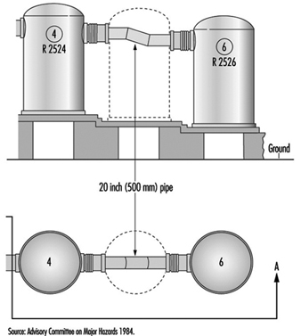
Accident Case: Flixborough
The explosion of a large cloud of cyclohexane in Flixborough (UK) in 1974, which killed 28 persons and caused extensive plant damage, serves as a very instructive case. The triggering event was the breakdown of a temporary pipe serving as a substitute in a reactor unit. The accident was “caused” by a piece of hardware breaking down, but on closer investigation it was revealed that the breakdown followed from overload, and that the temporary construction was in fact inadequate for its intended use. After two months’ service, the pipe was exposed to bending forces due to a slight pressure rise of the 10-bar (106 Pa) cyclohexane content at about 150°C. The two bellows between the pipe and the nearby reactors broke and 30 to 50 tonnes of cyclohexane was released and soon ignited, probably by a furnace some distance from the leak. (See figure 1.) A very readable account of the case is found in Kletz (1988).
Figure 1. Temporary connection between tanks at Flixborough
Hazard Analysis
The methods that have been developed to find the risks that may be relevant to a piece of equipment, to a chemical process or to a certain operation are referred to as “hazard analysis”. These methods ask questions such as: “What may possibly go wrong?” “Could it be serious?” and “What can be done about it?” Different methods of conducting the analyses are often combined to achieve a reasonable coverage, but no such set can do more than guide or assist a clever team of analysts in their determinations. The main difficulties with hazard analysis are as follows:
- availability of relevant data
- limitations of models and calculations
- new and unfamiliar materials, constructions and processes
- system complexity
- limitations on human imagination
- limitations on practical tests.
To produce usable risk evaluations under these circumstances it is important to stringently define the scope and the level of “ambitiousness” appropriate to the analysis at hand; for example, it is clear that one does not need the same sort of information for insurance purposes as for design purposes, or for the planning of protection schemes and the construction of emergency arrangements. Generally speaking, the risk picture must be filled in by mixing empirical techniques (i.e., statistics) with deductive reasoning and a creative imagination.
Different risk evaluation tools - even computer programs for risk analysis—can be very helpful. The hazard and operability study (HAZOP) and the failure mode and effect analysis (FMEA ) are commonly used methods for investigating hazards, especially in the chemical industry. The point of departure for the HAZOP method is the tracing of possible risk scenarios based on a set of guide words; for each scenario one has to identify probable causes and consequences. In the second stage, one tries to find means for reducing the probabilities or mitigating the consequences of those scenarios judged to be unacceptable. A review of the HAZOP method can be found in Charsley (1995). The FMEA method asks a series of “what if” questions for every possible risk component in order to thoroughly determine whatever failure modes may exist and then to identify the effects that they may have on system performance; such an analysis will be illustrated in the demonstration example (for a gas system) presented later in this article.
Fault trees and event trees and the modes of logical analysis proper to accident causation structures and probability reasoning are in no way specific to the analysis of hardware hazards, as they are general tools for system risk evaluations.
Tracing hardware hazards in an industrial plant
To identify possible hazards, information on construction and function can be sought from:
- actual equipment and plant
- substitutes and models
- drawings, electrical diagrams, piping and instrumentation (P/I) diagrams, etc.
- process descriptions
- control schemes
- operation modes and phases
- work orders, change orders, maintenance reports, etc.
By selecting and digesting such information, analysts form a picture of the risk object itself, its functions and its actual use. Where things are not yet constructed - or unavailable for inspection - important observations cannot be made and the evaluation must be based entirely on descriptions, intentions and plans. Such evaluation might seem rather poor, but in fact, most practical risk evaluations are made this way, either in order to seek authoritative approval for applications to undertake new construction, or to compare the relative safety of alternative design solutions. Real life processes will be consulted for the information not shown on the formal diagrams or described verbally by interview, and to verify that the information gathered from these sources is factual and represents actual conditions. These include the following:
- actual practice and culture
- additional failure mechanisms/construction details
- “sneak paths” (see below)
- common error causes
- risks from external sources/missiles
- particular exposures or consequences
- past incidents, accidents and near accidents.
Most of this additional information, especially sneak paths, is detectable only by creative, skilled observers with considerable experience, and some of the information would be almost impossible to trace with maps and diagrams. Sneak paths denote unintended and unforeseen interactions between systems, where the operation of one system affects the condition or operation of another system through other ways than the functional ones. This typically happens where functionally different parts are situated near each other, or (for example) a leaking substance drips on equipment beneath and causes a failure. Another mode of a sneak path’s action may involve the introduction of wrong substances or parts into a system by means of instruments or tools during operation or maintenance: the intended structures and their intended functions are changed through the sneak paths. By common-mode failures one means that certain conditions - like flooding, lightning or power failure - can disturb several systems at once, perhaps leading to unexpectedly large blackouts or accidents. Generally, one tries to avoid sneak-path effects and common-mode failures through proper layouts and introducing distance, insulation and diversity in working operations.
A Hazards Analysis Case: Gas Delivery from a Ship to a Tank
Figure 2 shows a system for delivery of gas from a transport ship to a storage tank. A leak could appear anywhere in this system: ship, transmission line, tank or output line; given the two tank reservoirs, a leak somewhere on the line could remain active for hours.
Figure 2. Transmission line for delivery of liquid gas from ship to storage tank
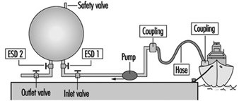
The most critical components of the system are the following:
- the storage tank
- the pipeline or hose between the tank and the ship
- other hoses, lines, valves and connections
- the safety valve on the storage tank
- the emergency shut-down valves ESD 1 and 2.
A storage tank with a large inventory of liquid gas is put at the top of this list, because it is difficult to stop a leak from a tank on short notice. The second item on the list - the connection to the ship - is critical because leaks in the pipe or hose and loose connections or couplings with worn gaskets, and variations among different ships, could release product. Flexible parts like hoses and bellows are more critical than rigid parts, and require regular maintenance and inspection. Safety devices like the pressure release valve on the top of the tank and the two emergency shut-down valves are critical, since they must be relied upon to reveal latent or developing failures.
Up to this point, the ranking of system components as to their importance with respect to reliability has been of a general nature only. Now, for analytical purposes, attention will be drawn to the particular functions of the system, the chief one of course being the movement of liquefied gas from the ship to the storage tank until the connected ship tank is empty. The overriding hazard is a gas leak, the possible contributory mechanisms being one of more of the following:
- leaking couplings or valves
- tank rupture
- rupture of pipe or hose
- tank breakdown.
Application of the FMEA method
The central idea of the FMEA approach, or “what if” analysis, is to record explicitly, for each component of the system, its failure modes, and for every failure to find the possible consequences to the system and to the environment. For standard components like a tank, pipe, valve, pump, flowmeter and so on, the failure modes follow general patterns. In the case of a valve, for instance, failure modes could include the following conditions:
- The valve cannot close on demand (there is reduced flow through an “open” valve).
- The valve leaks (there is residual flow through a “closed” valve).
- The valve cannot open on demand (the valve position oscillates).
For a pipeline, failure modes would consider items such as:
- a reduced flow
- a leak
- a flow stopped due to blockage
- a break in the line.
The effects of leaks seem obvious, but sometimes the most important effects may not be the first effects: what happens for example, if a valve is stuck in a half-open position? An on-off valve in the delivery line that does not open completely on demand will delay the tank filling process, a non-dangerous consequence. But if the “stuck half-open” condition arises at the same time that a closing demand is made, at a time when the tank is almost full, overfilling might result (unless the emergency shut-down valve is successfully activated). In a properly designed and operated system, the probability of both these valves being stuck simultaneously will be kept rather low.
Plainly a safety valve’s not operating on demand could mean disaster; in fact, one might justifiably state that latent failures are constantly threatening all safety devices. Pressure relief valves, for instance, can be defective due to corrosion, dirt or paint (typically due to bad maintenance), and in the case of liquid gas, such defects in combination with the temperature decrease at a gas leak could produce ice and thereby reduce or perhaps stop the flow of material through a safety valve. If a pressure relief valve does not operate on demand, pressure may build up in a tank or in connected systems of tanks, eventually causing other leaks or tank rupture.
For simplicity, instruments are not shown on figure 2; there will of course be instruments related to pressure, flow and temperature, which are essential parameters for monitoring the system state, relevant signals being transmitted to operator consoles or to a control room for control and monitoring purposes. Furthermore, there will be supply lines other than those intended for materials transport - for electricity, hydraulics and so forth - and extra safety devices. A comprehensive analysis must go through these systems as well and look for the failure modes and effects of these components also. In particular, the detective work on common-mode effects and sneak paths requires one to construct the integral picture of main system components, controls, instruments, supplies, operators, working schedules, maintenance and so on.
Examples of common-mode effects to consider in connection with gas systems are addressed by such questions as these:
- Are activation signals for delivery valves and emergency shut-down valves transmitted on a common line (cable, cabling channels)?
- Do two given valves share the same power line?
- Is maintenance performed by the same person according to a given schedule?
Even an excellently designed system with redundancy and independent power lines can suffer from inferior maintenance, where, for example, a valve and its back-up valve (the emergency shut-down valve in our case) have been left in a wrong state after a test. A prominent common-mode effect with an ammonia-handling system is the leak situation itself: a moderate leak can make all manual operations on plant components rather awkward - and delayed - due to the deployment of the required emergency protection.
Summary
The hardware components are very seldom the guilty parts in accident development; rather, there are root causes to be found in other links of the chain: wrong concepts, bad designs, maintenance errors, operator errors, management errors and so on. Several examples of the specific conditions and acts that may lead to failure development have already been given; a broad collection of such agents would take account of the following:
- collision
- corrosion, etching
- excessive loads
- failing support and aged or worn-out parts
- low-quality welding jobs
- missiles
- missing parts
- overheating or chilling
- vibration
- wrong construction material used.
Controlling the hardware hazards in a working environment requires the review of all possible causes and respect for the conditions that are found to be critical with the actual systems. The implications of this for the organization of risk management programmes are dealt with in other articles, but, as the foregoing list clearly indicates, the monitoring and control of hardware conditions can be necessary all the way back to the choice of concepts and designs for the selected systems and processes.