There are underground mines all over the world presenting a kaleidoscope of methods and equipment. There are approximately 650 underground mines, each with an annual output that exceeds 150,000 tonnes, which account for 90% of the ore output of the western world. In addition, it is estimated that there are 6,000 smaller mines each producing less than 150,000 tonnes. Each mine is unique with workplace, installations and underground workings dictated by the kinds of minerals being sought and the location and geological formations, as well as by such economic considerations as the market for the particular mineral and the availability of funds for investment. Some mines have been in continuous operation for more than a century while others are just starting up.
Mines are dangerous places where most of the jobs involve arduous labour. The hazards faced by the workers range from such catastrophes as cave-ins, explosions and fire to accidents, dust exposure, noise, heat and more. Protecting the health and safety of the workers is a major consideration in properly conducted mining operations and, in most countries, is required by laws and regulations.
The Underground Mine
The underground mine is a factory located in the bedrock inside the earth in which miners work to recover minerals hidden in the rock mass. They drill, charge and blast to access and recover the ore, i.e., rock containing a mix of minerals of which at least one can be processed into a product that can be sold at a profit. The ore is taken to the surface to be refined into a high-grade concentrate.
Working inside the rock mass deep below the surface requires special infrastructures: a network of shafts, tunnels and chambers connecting with the surface and allowing movement of workers, machines and rock within the mine. The shaft is the access to underground where lateral drifts connect the shaft station with production stopes. The internal ramp is an inclined drift which links underground levels at different elevations (i.e., depths). All underground openings need services such as exhaust ventilation and fresh air, electric power, water and compressed air, drains and pumps to collect seeping ground water, and a communication system.
Hoisting plant and systems
The headframe is a tall building which identifies the mine on the surface. It stands directly above the shaft, the mine’s main artery through which the miners enter and leave their workplace and through which supplies and equipment are lowered and ore and waste materials are raised to the surface. Shaft and hoist installations vary depending on the need for capacity, depth and so on. Each mine must have at least two shafts to provide an alternate route for escape in case of an emergency.
Hoisting and shaft travelling are regulated by stringent rules. Hoisting equipment (e.g., winder, brakes and rope) is designed with ample margins of safety and is checked at regular intervals. The shaft interior is regularly inspected by people standing on top of the cage, and stop buttons at all stations trigger the emergency brake.
The gates in front of the shaft barricade the openings when the cage is not at the station. When the cage arrives and comes to a full stop, a signal clears the gate for opening. After miners have entered the cage and closed the gate, another signal clears the cage for moving up or down the shaft. Practice varies: the signal commands may be given by a cage tender or, following the instructions posted at each shaft station, the miners may signal shaft destinations for themselves. Miners are generally quite aware of the potential hazards in shaft riding and hoisting and accidents are rare.
Diamond drilling
A mineral deposit inside the rock must be mapped before the start of mining. It is necessary to know where the orebody is located and define its width, length and depth to achieve a three-dimensional vision of the deposit.
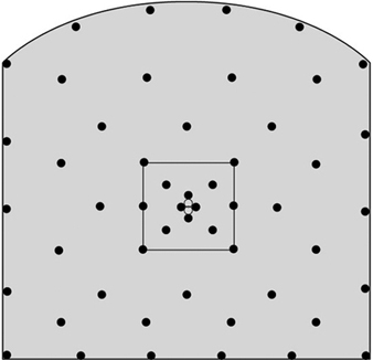
Diamond drilling is used to explore a rock mass. Drilling can be done from the surface or from the drift in the underground mine. A drill bit studded with small diamonds cuts a cylindrical core that is captured in the string of tubes that follows the bit. The core is retrieved and analysed to find out what is in the rock. Core samples are inspected and the mineralized portions are split and analysed for metal content. Extensive drilling programmes are required to locate the mineral deposits; holes are drilled at both horizontal and vertical intervals to identify the dimensions of the orebody (see figure 1).
Figure 1. Drill pattern, Garpenberg Mine, a lead-zinc mine, Sweden
Mine development
Mine development involves the excavations needed to establish the infrastructure necessary for stope production and to prepare for the future continuity of operations. Routine elements, all produced by the drill-blast-excavation technique, include horizontal drifts, inclined ramps and vertical or inclined raises.
Shaft sinking
Shaft sinking involves rock excavation advancing downwards and is usually assigned to contractors rather than being done by mine’s personnel. It requires experienced workers and special equipment, such as a shaft-sinking headframe, a special hoist with a large bucket hanging in the rope and a cactus-grab shaft mucking device.
The shaft-sinking crew is exposed to a variety of hazards. They work at the bottom of a deep, vertical excavation. People, material and blasted rock must all share the large bucket. People at the shaft bottom have no place to hide from falling objects. Clearly, shaft sinking is not a job for the inexperienced.
Drifting and ramping
A drift is a horizontal access tunnel used for transport of rock and ore. Drift excavation is a routine activity in the development of the mine. In mechanized mines, two-boom, electro-hydraulic drill jumbos are used for face drilling. Typical drift profiles are 16.0 m2 in section and the face is drilled to a depth of 4.0 m. The holes are charged pneumatically with an explosive, usually bulk ammonium nitrate fuel oil (ANFO), from a special charging truck. Short-delay non-electric (Nonel) detonators are used.
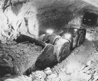
Mucking is done with (load-haul-dump) LHD vehicles (see figure 2) with a bucket capacity of about 3.0 m3. Muck is hauled directly to the ore pass system and transferred to truck for longer hauls. Ramps are passageways connecting one or more levels at grades ranging from 1:7 to 1:10 (a very steep grade compared to normal roads) that provide adequate traction for heavy, self-propelled equipment. The ramps are often driven in an upward or downward spiral, similar to a spiral staircase. Ramp excavation is a routine in the mine’s development schedule and uses the same equipment as drifting.
Figure 2. LHD loader
Atlas Copco
Raising
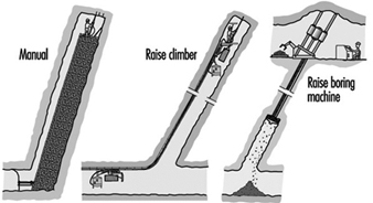
A raise is a vertical or steeply-inclined opening that connects different levels in the mine. It may serve as a ladderway access to stopes, as an ore pass or as an airway in the mine’s ventilation system. Raising is a difficult and dangerous, but necessary job. Raising methods vary from simple manual drill and blast to mechanical rock excavation with raise boring machines (RBMs) (see figure 3).
Figure 3. Raising methods
Manual raising
Manual raising is difficult, dangerous and physically demanding work that challenges the miner’s agility, strength and endurance. It is a job to be assigned only to experienced miners in good physical condition. As a rule the raise section is divided into two compartments by a timbered wall. One is kept open for the ladder used for climbing to the face, air pipes, etc. The other fills with rock from blasting which the miner uses as a platform when drilling the round. The timber parting is extended after each round. The work involves ladder climbing, timbering, rock drilling and blasting, all done in a cramped, poorly ventilated space. It is all performed by a single miner, as there is no room for a helper. Mines search for alternatives to the hazardous and laborious manual raising methods.
The raise climber
The raise climber is a vehicle that obviates ladder climbing and much of the difficulty of the manual method. This vehicle climbs the raise on a guide rail bolted to the rock and provides a robust working platform when the miner is drilling the round above. Very high raises can be excavated with the raise climber with safety much improved over the manual method. Raise excavation, however, remains a very hazardous job.
The raise boring machine
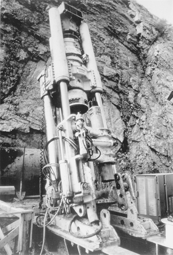
The RBM is a powerful machine that breaks the rock mechanically (see figure 4). It is erected on top of the planned raise and a pilot hole about 300 mm in diameter is drilled to break through at a lower level target. The pilot drill is replaced by a reamer head with the diameter of the intended raise and the RBM is put in reverse, rotating and pulling the reamer head upward to create a full-size circular raise.
Figure 4. Raise boring machine
Atlas Copco
Ground control
Ground control is an important concept for people working inside a rock mass. It is particularly important in mechanized mines using rubber-tyred equipment where the drift openings are 25.0 m2 in section, in contrast to the mines with rail drifts where they are usually only 10.0 m2. The roof at 5.0 m is too high for a miner to use a scaling bar to check for potential rock falls.
Different measures are used to secure the roof in underground openings. In smooth blasting, contour holes are drilled closely together and charged with a low-strength explosive. The blast produces a smooth contour without fracturing the outside rock.
Nevertheless, since there are often cracks in the rock mass which do not show on the surface, rock falls are an ever-present hazard. The risk is reduced by rock bolting, i.e., insertion of steel rods in bore holes and fastening them. The rock bolt holds the rock mass together, prevents cracks from spreading, helps to stabilize the rock mass and makes the underground environment safer.
Methods for Underground Mining
The choice of mining method is influenced by the shape and size of the ore deposit, the value of the contained minerals, the composition, stability and strength of the rock mass and the demands for production output and safe working conditions (which sometimes are in conflict). While mining methods have been evolving since antiquity, this article focuses on those used in semi- to fully-mechanized mines during the late twentieth century. Each mine is unique, but they all share the goals of a safe workplace and a profitable business operation.
Flat room-and-pillar mining
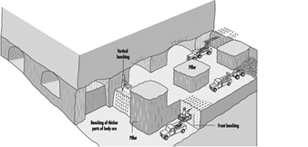
Room-and-pillar mining is applicable to tabular mineralization with horizontal to moderate dip at an angle not exceeding 20° (see figure 5). The deposits are often of sedimentary origin and the rock is often in both hanging wall and mineralization in competent (a relative concept here as miners have the option to install rock bolts to reinforce the roof where its stability is in doubt). Room-and-pillar is one of the principal underground coal-mining methods.
Figure 5. Room-and-pillar mining of a flat orebody
Room-and-pillar extracts an orebody by horizontal drilling advancing along a multi-faced front, forming empty rooms behind the producing front. Pillars, sections of rock, are left between the rooms to keep the roof from caving. The usual result is a regular pattern of rooms and pillars, their relative size representing a compromise between maintaining the stability of the rock mass and extracting as much of the ore as possible. This involves careful analysis of the strength of the pillars, the roof strata span capacity and other factors. Rock bolts are commonly used to increase the strength of the rock in the pillars. The mined-out stopes serve as roadways for trucks transporting the ore to the mine’s storage bin.
The room-and-pillar stope face is drilled and blasted as in drifting. The stope width and height correspond to the size of the drift, which can be quite large. Large productive drill jumbos are used in normal height mines; compact rigs are used where the ore is less than 3.0 m thick. The thick orebody is mined in steps starting from the top so that the roof can be secured at a height convenient for the miners. The section below is recovered in horizontal slices, by drilling flat holes and blasting against the space above. The ore is loaded onto trucks at the face. Normally, regular front-end loaders and dump trucks are used. For the low-height mine, special mine trucks and LHD vehicles are available.
Room-and-pillar is an efficient mining method. Safety depends on the height of the open rooms and ground control standards. The main risks are accidents caused by falling rock and moving equipment.
Inclined room-and-pillar mining
Inclined room-and-pillar applies to tabular mineralization with an angle or dip from 15° and 30° to the horizontal. This is too steep an angle for rubber-tyred vehicles to climb and too flat for a gravity assist rock flow.
The traditional approach to the inclined orebody relies on manual labour. The miners drill blast holes in the stopes with hand-held rock drills. The stope is cleaned with slusher scrapers.
The inclined stope is a difficult place to work. The miners have to climb the steep piles of blasted rock carrying with them their rock drills and the drag slusher pulley and steel wires. In addition to rock falls and accidents, there are the hazards of noise, dust, inadequate ventilation and heat.
Where the inclined ore deposits are adaptable to mechanization, “step-room mining” is used. This is based on converting the “difficult dip” footwall into a “staircase” with steps at an angle convenient for trackless machines. The steps are produced by a diamond pattern of stopes and haulage-ways at the selected angle across the orebody.
Ore extraction starts with horizontal stope drives, branching out from a combined access-haulage drift. The initial stope is horizontal and follows the hanging wall. The next stope starts a short distance further down and follows the same route. This procedure is repeated moving downward to create a series of steps to extract the orebody.
Sections of the mineralization are left to support the hanging wall. This is done by mining two or three adjacent stope drives to the full length and then starting the next stope drive one step down, leaving an elongated pillar between them. Sections of this pillar can later be recovered as cut-outs that are drilled and blasted from the stope below.
Modern trackless equipment adapts well to step-room mining. The stoping can be fully mechanized, using standard mobile equipment. The blasted ore is gathered in the stopes by the LHD vehicles and transferred to mine truck for transport to the shaft/ore pass. If the stope is not high enough for truck loading, the trucks can be filled in special loading bays excavated in the haulage drive.
Shrinkage stoping
Shrinkage stoping may be termed a “classic” mining method, having been perhaps the most popular mining method for most of the past century. It has largely been replaced by mechanized methods but is still used in many small mines around the world. It is applicable to mineral deposits with regular boundaries and steep dip hosted in a competent rock mass. Also, the blasted ore must not be affected by storage in the slopes (e.g., sulphide ores have a tendency to oxidize and decompose when exposed to air).
Its most prominent feature is the use of gravity flow for ore handling: ore from stopes drops directly into rail cars via chutes obviating manual loading, traditionally the most common and least liked job in mining. Until the appearance of the pneumatic rocker shovel in the 1950s, there was no machine suitable for loading rock in underground mines.
Shrinkage stoping extracts the ore in horizontal slices, starting at the stope bottoms and advancing upwards. Most of the blasted rock remains in the stope providing a working platform for the miner drilling holes in the roof and serving to keep the stope walls stable. As blasting increases the volume of the rock by about 60%, some 40% of the ore is drawn at the bottom during stoping in order to maintain a work space between the top of the muckpile and the roof. The remaining ore is drawn after blasting has reached the upper limit of the stope.
The necessity of working from the top of the muckpile and the raise-ladder access prevents the use of mechanized equipment in the stope. Only equipment light enough for the miner to handle alone may be used. The air-leg and rock drill, with a combined weight of 45 kg, is the usual tool for drilling the shrinkage stope. Standing on top of the muckpile, the miner picks up the drill/feed, anchors the leg, braces the rock drill/drill steel against the roof and starts drilling; it is not easy work.
Cut-and-fill mining
Cut-and-fill mining is suitable for a steeply dipping mineral deposit contained in a rock mass with good to moderate stability. It removes the ore in horizontal slices starting from a bottom cut and advances upwards, allowing the stope boundaries to be adjusted to follow irregular mineralization. This permits high-grade sections to be mined selectively, leaving low-grade ore in place.
After the stope is mucked clean, the mined out space is backfilled to form a working platform when the next slice is mined and to add stability to the stope walls.
Development for cut-and-fill mining in a trackless environment includes a footwall haulage drive along the orebody at the main level, undercut of the stope provided with drains for the hydraulic backfill, a spiral ramp excavated in the footwall with access turn-outs to the stopes and a raise from the stope to the level above for ventilation and fill transport.
Overhand stoping is used with cut-and-fill, with both dry rock and hydraulic sand as backfill material. Overhand means that the ore is drilled from below by blasting a slice 3.0 m to 4.0 m thick. This allows the complete stope area to be drilled and the blasting of the full stope without interruptions. The “uppers” holes are drilled with simple wagon drills.
Up-hole drilling and blasting leaves a rough rock surface for the roof; after mucking out, its height will be about 7.0 m. Before miners are allowed to enter the area, the roof must be secured by trimming the roof contours with smooth-blasting and subsequent scaling of the loose rock. This is done by miners using hand-held rock drills working from the muckpile.
In front stoping, trackless equipment is used for ore production. Sand tailings are used for backfill and distributed in the underground stopes via plastic pipes. The stopes are filled almost completely, creating a surface sufficiently hard to be traversed by rubber-tyred equipment. The stope production is completely mechanized with drifting jumbos and LHD vehicles. The stope face is a 5.0 m vertical wall across the stope with a 0.5 m open slot beneath it. Five-meter-long horizontal holes are drilled in the face and ore is blasted against the open bottom slot.
The tonnage produced by a single blast depends on the face area and does not compare to that yielded by the overhand stope blast. However, the output of trackless equipment is vastly superior to the manual method, while roof control can be accomplished by the drill jumbo which drills smooth-blast holes together with the stope blast. Fitted with an oversize bucket and large tyres, the LHD vehicle, a versatile tool for mucking and transport, travels easily on the fill surface. In a double face stope, the drill jumbo engages it on one side while the LHD handles the muckpile at the other end, providing efficient use of the equipment and enhancing the production output.
Sublevel stoping removes ore in open stopes. Backfilling of stopes with consolidated fill after the mining allows the miners to return at a later time to recover the pillars between the stopes, enabling a very high recovery rate of the mineral deposit.
Development for sublevel stoping is extensive and complex. The orebody is divided into sections with a vertical height of about 100 m in which sublevels are prepared and connected via an inclined ramp. The orebody sections are further divided laterally in alternating stopes and pillars and a mail haulage drive is created in the footwall, at the bottom, with cut-outs for drawpoint loading.
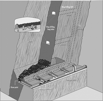
When mined out, the sublevel stope will be a rectangular opening across the orebody. The bottom of the stope is V-shaped to funnel the blasted material into the draw-points. Drilling drifts for the long-hole rig are prepared on the upper sublevels (see figure 6).
Figure 6. Sublevel stoping using ring drilling & cross-cut loading
Blasting requires space for the rock to expand in volume. This requires that a slot a few metres wide be prepared before the start of long-hole blasting. This is accomplished by enlarging a raise from the bottom to the top of the stope to a full slot.
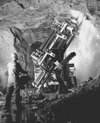
After opening the slot, the long-hole rig (see figure 7) begins production drilling in sublevel drifts following precisely a detailed plan designed by blasting experts which specifies all the blast holes, the collaring position, depth and direction of the holes. The drill rig continues drilling until all the rings on one level are completed. It is then transferred to the next sublevel to continue drilling. Meanwhile the holes are charged and a blast pattern which covers a large area within the stope breaks up a large volume of ore in one blast. The blasted ore drops to the stope bottom to be recovered by the LHD vehicles mucking in the draw-point beneath the stope. Normally, the long-hole drilling stays ahead of the charging and blasting providing a reserve of ready-to-blast ore, thus making for an efficient production schedule.
Figure 7. Long-hole drill rig
Atlas Copco
Sublevel stoping is a productive mining method. Efficiency is enhanced by the ability to use fully mechanized productive rigs for the long-hole drilling plus the fact that the rig can be used continuously. It is also relatively safe because doing the drilling inside sublevel drifts and mucking through draw-points eliminates exposure to potential rock falls.
Vertical crater retreat mining
Like sublevel stoping and shrinkage stoping, vertical crater retreat (VCR) mining is applicable to mineralization in steeply dipping strata. However, it uses a different blasting technique breaking the rock with heavy, concentrated charges placed in holes (“craters”) with very large diameter (about 165 mm) about 3 m away from a free rock surface. Blasting breaks a cone-shaped opening in the rock mass around the hole and allows the blasted material to remain in the stope during the production phase so that the rock fill can assist in supporting the stope walls. The need for rock stability is less than in sublevel stoping.
The development for VCR mining is similar to that for sublevel stoping except for requiring both over-cut and under-cut excavations. The over-cut is needed in the first stage to accommodate the rig drilling the large-diameter blast holes and for access while charging the holes and blasting. The under-cut excavation provided the free surface necessary for VCR blasting. It may also provide access for a LHD vehicle (operated by remote control with the operator remaining outside the stope) to recover the blasted ore from the draw-points beneath the stope.
The usual VCR blast uses holes in a 4.0 × 4.0 m pattern directed vertically or steeply inclined with charges carefully placed at calculated distances to free the surface beneath. The charges cooperate to break off a horizontal ore slice about 3.0 m thick. The blasted rock falls into the stope underneath. By controlling the rate of mucking out, the stope remains partly filled so that the rock fill assists in stabilizing the stope walls during the production phase. The last blast breaks the over-cut into the stope, after which the stope is mucked clean and prepared for back filling.
VCR mines often uses a system of primary and secondary stopes to the orebody. Primary stopes are mined in the first stage, then backfilled with cemented fill. The stope is left for the fill to consolidate. Miners then return and recover the ore in the pillars between the primary stopes, the secondary stopes. This system, in combination with the cemented backfill, results in close to a 100% recovery of the ore reserves.
Sublevel caving
Sublevel caving is applicable to mineral deposits with steep to moderate dip and large extension at depth. The ore must fracture into manageable block with blasting. The hanging wall will cave following the ore extraction and the ground on the surface above the orebody will subside. (It must be barricaded to prevent any individuals from entering the area.)
Sublevel caving is based on gravity flow inside a broken-up rock mass containing both ore and rock. The rock mass is first fractured by drilling and blasting and then mucked out through drift headings underneath the rock mass cave. It qualifies as a safe mining method because the miners always work inside drift-size openings.
Sublevel caving depends on sublevels with regular patterns of drifts prepared inside the orebody at rather close vertical spacing (from 10.0 m to 20 0 m). The drift layout is the same on each sublevel (i.e., parallel drives across the orebody from the footwall transport drive to the hanging wall) but the patterns on each sublevel are slightly off-set so that the drifts on a lower level are located between the drifts on the sublevel above it. A cross section will show a diamond pattern with drifts in regular vertical and horizontal spacing. Thus, development for sublevel caving is extensive. Drift excavation, however, is a straightforward task which can readily be mechanized. Working on multiple drift headings on several sublevels favours high utilization of the equipment.
When the development of the sublevel is completed, the long-hole drill rig moves in to drill a blast holes in a fan-spread pattern in the rock above. When all of the blast holes are ready, the long-hole drill rig is moved to the sublevel below.
The long-hole blast fractures the rock mass above the sublevel drift, initiating a cave that starts at the hanging wall contact and retreats toward the footwall following a straight front across the orebody on the sublevel. A vertical section would show a staircase where each upper sublevel is one step ahead of the sublevel below.
The blast fills the sublevel front with a mix of ore and waste. When the LHD vehicle arrives, the cave contains 100% ore. As loading continues, the proportion of waste rock will gradually increase until the operator decides that the waste dilution is too high and stops loading. As the loader moves to the next drift to continue mucking, the blaster enters to prepare the next ring of holes for blasting.
Mucking out on sublevels is an ideal application for the LHD vehicle. Available in different sizes to meet particular situations, it fills the bucket, travels some 200 m, empties the bucket into the ore pass and returns for another load.
Sublevel caving features a schematic layout with repetitive work procedures (development drifting, long-hole drilling, charging and blasting, loading and transport) that are carried out independently. This allows the procedures to move continuously from one sublevel to another, allowing for the most efficient use of work crews and equipment. In effect the mine is analogous to a departmentalized factory. Sublevel mining, however, being less selective than other methods, does not yield particularly efficient extraction rates. The cave includes some 20 to 40% of waste with a loss of ore that ranges from 15 to 25%.
Block-caving
Block-caving is a large-scale method applicable to mineralization on the order of 100 million tonnes in all directions contained in rock masses amenable to caving (i.e., with internal stresses which, after removal of the supporting elements in the rock mass, assist the fracturing of the mined block). An annual output ranging from 10 to 30 million tonnes is the anticipated yield. These requirements limit block-caving to a few specific mineral deposits. Worldwide, there are block-caving mines exploiting deposits containing copper, iron, molybdenum and diamonds.
Block refers to the mining layout. The orebody is divided into large sections, blocks, each containing a tonnage sufficient for many years of production. The caving is induced by removing the supporting strength of the rock mass directly underneath the block by means of an undercut, a 15 m high section of rock fractured by long-hole drilling and blasting. Stresses created by natural tectonic forces of considerable magnitude, similar to those causing continental movements, create cracks in the rock mass, breaking the blocks, hopefully to pass draw-point openings in the mine. Nature, though, often needs the assistance of miners to handle oversize boulders.
Preparation for block-caving requires long-range planning and extensive initial development involving a complex system of excavations beneath the block. These vary with the site; they generally include undercut, drawbells, grizzlies for control of oversize rock and ore passes that funnel the ore into train loading.
Drawbells are conical openings excavated underneath the undercut which gather ore from a large area and funnel it into the drawpoint at the production level below. Here the ore is recovered in LHD vehicles and transferred to ore passes. Boulders too large for the bucket are blasted in draw-points, while smaller ones are dealt with on the grizzly. Grizzlies, sets of parallel bars for screening coarse material, are commonly used in block-caving mines although, increasingly, hydraulic breakers are being preferred.
Openings in a block-caving mine are subject to high rock pressure. Drifts and other openings, therefore, are excavated with the smallest possible section. Nevertheless, extensive rock bolting and concrete lining is required to keep the openings intact.
Properly applied, block-caving is a low-cost, productive mass mining method. However, the amenability of a rock mass to caving is not always predictable. Also, the comprehensive development that is required results in a long lead-time before the mine starts producing: the delay in earnings can have a negative influence on the financial projections used to justify the investment.
Longwall mining
Longwall mining is applicable to bedded deposits of uniform shape, limited thickness and large horizontal extension (e.g., a coal seam, a potash layer or the reef, the bed of quartz pebbles exploited by gold mines in South Africa). It is one of the main methods for mining coal. It recovers the mineral in slices along a straight line that are repeated to recover materials over a larger area. The space closest to the face in kept open while the hanging wall is allowed to collapse at a safe distance behind the miners and their equipment.
Preparation for longwall mining involves the network of drifts required for access to the mining area and transport of the mined product to the shaft. Since the mineralization is in the form of a sheet that extends over a wide area, the drifts can usually be arranged in a schematic network pattern. The haulage drifts are prepared in the seam itself. The distance between two adjacent haulage drifts determines the length of the longwall face.
Backfilling
Backfilling of mine stopes prevents rock from collapsing. It preserves the inherent stability of the rock mass which promotes safety and allows more complete extraction of the desired ore. Backfilling is traditionally used with cut-and-fill but it is also common with sublevel stoping and VCR mining.
Traditionally, miners have dumped waste rock from development in empty stopes instead of hauling it to the surface. For example, in cut-and-fill, waste rock is distributed over the empty stope by scrapers or bulldozers.
Hydraulic backfilling uses tailings from the mine’s dressing plant which are distributed underground through bore holes and plastic tubing. The tailings are first de-slimed, only the coarse fraction being used for filling. The fill is a mix of sand and water, about 65% of which is solid matter. By mixing cement into the last pour, the fill’s surface will harden into a smooth roadbed for rubber-tyred equipment.
Backfilling is also used with sublevel stoping and VCR mining, with crushed rock introduced as a complement to sand fill. The crushed and screened rock, produced in a nearby quarry, is delivered underground through special backfill raises where it is loaded on trucks and delivered to the stopes where it is dumped into special fill raises. Primary stopes are backfilled with cemented rock fill produced by spraying a cement-fly ash slurry on the rockfill before it is distributed to the stopes. The cemented rockfill hardens into a solid mass forming an artificial pillar for mining the secondary stope. The cement slurry is generally not required when secondary stopes are backfilled, except for the last pours to establish a firm mucking floor.
Equipment for Underground Mining
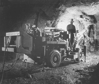
Underground mining is becoming increasingly mechanized wherever circumstances permit. The rubber-tyred, diesel-powered, four-wheel traction, articulated steer carrier is common to all mobile underground machines (see figure 8).
Figure 8. Small-size face rig
Atlas Copco
Face drill jumbo for development drilling
This is an indispensable workhorse in mines that is used for all rock excavation work. It carries one or two booms with hydraulic rock drills. With one worker at the control panel, it will complete a pattern of 60 blast holes 4.0 m deep in a few hours.
Long-hole production drill rig
This rig (see figure 7 drills blast holes in a radial spread around the drift which cover a large area of rock and break off large volumes of ore. It is used with sublevel stoping, sublevel caving, block-caving and VCR mining. With a powerful hydraulic rock drill and carousel storage for extension rods, the operator uses remote controls to perform rock drilling from a safe position.
Charging truck
The charging truck is a necessary complement to the drifting jumbo. The carrier mounts a hydraulic service platform, a pressurized ANFO explosive container and a charging hose that permit the operator to fill blast holes all over the face in a very short time. At the same time, Nonel detonators may be inserted for the correct timing of the individual blasts.
LHD vehicle
The versatile load-haul-dump vehicle (see figure 10) is used for a variety of services including ore production and materials handling. It is available in a choice of sizes allowing miners to select the model most appropriate for each task and each situation. Unlike the other diesel vehicles used in mines, the LHD vehicle engine is generally run continuously at full power for long periods of time generating large volumes of smoke and exhaust fumes. A ventilation system capable of diluting and exhausting these fumes is essential to compliance with acceptable breathing standards in the loading area.
Underground haulage
The ore recovered in stopes spread along an orebody is transported to an ore dump located close to the hoisting shaft. Special haulage levels are prepared for longer lateral transfer; they commonly feature rail track installations with trains for ore transport. Rail has proved to be an efficient transport system carrying larger volumes for longer distances with electric locomotives that do not contaminate the underground atmosphere like diesel-powered trucks used in trackless mines.
Ore handling
On its route from the stopes to the hoisting shaft, the ore passes several stations with a variety of materials-handling techniques.
The slusher uses a scraper bucket to draw ore from the stope to the ore pass. It is equipped with rotating drums, wires and pulleys, arranged to produce a back and forth scraper route. The slusher does not need preparation of the stope flooring and can draw ore from a rough muckpile.
The LHD vehicle, diesel powered and travelling on rubber tyres, takes the volume held in its bucket (sizes vary) from the muckpile to the ore pass.
The ore pass is a vertical or steeply inclined opening through which rock flows by gravity from upper to lower levels. Ore passes are sometimes arranged in a vertical sequence to collect ore from upper levels to a common delivery point on the haulage level.
The chute is the gate located at the bottom of the ore pass. Ore passes normally end in rock close to the haulage drift so that, when the chute is opened, the ore can flow to fill cars on the track beneath it.
Close to the shaft, the ore trains pass a dump station where the load may be dropped into a storage bin, A grizzly at the dump station stops oversized rocks from falling into the bin. These boulders are split by blasting or hydraulic hammers; a coarse crusher may be installed below the grizzly for further size control. Under the storage bin is a measure pocket which automatically verifies that the load’s volume and weight do not exceed the capacities of the skip and the hoist. When an empty skip, a container for vertical travel, arrives at the filling station, a chute opens in the bottom of the measure pocket filling the skip with a proper load. After the hoist lifts the loaded skip to the headframe on the surface, a chute opens to discharge the load into the surface storage bin. Skip hoisting can be automatically operated using closed-circuit television to monitor the process.

