- You are here:
-
Home

- k2 Feed
Confined Spaces
Confined spaces are ubiquitous throughout industry as recurring sites of both fatal and nonfatal accidents. The term confined space traditionally has been used to label particular structures, such as tanks, vessels, pits, sewers, hoppers and so on. However, a definition based on description in this manner is overly restrictive and defies ready extrapolation to structures in which accidents have occurred. Potentially any structure in which people work could be or could become a confined space. Confined spaces can be very large or they can be very small. What the term actually describes is an environment in which a broad range of hazardous conditions can occur. These condition include personal confinement, as well as structural, process, mechanical, bulk or liquid material, atmospheric, physical, chemical, biological, safety and ergonomic hazards. Many of the conditions produced by these hazards are not unique to confined spaces but are exacerbated by involvement of the boundary surfaces of the confined space.
Confined spaces are considerably more hazardous than normal workspaces. Seemingly minor alterations in conditions can immediately change the status of these workspaces from innocuous to life-threatening. These conditions may be transient and subtle, and therefore are difficult to recognize and to address. Work involving confined spaces generally occurs during construction, inspection, maintenance, modification and rehabilitation. This work is nonroutine, short in duration, nonrepetitive and unpredictable (often occurring during off-shift hours or when the unit is out of service).
Confined Space Accidents
Accidents involving confined spaces differ from accidents that occur in normal workspaces. A seemingly minor error or oversight in preparation of the space, selection or maintenance of equipment or work activity can precipitate an accident. This is because the tolerance for error in these situations is smaller than for normal workplace activity.
The occupations of victims of confined space accidents span the occupational spectrum. While most are workers, as might be expected, victims also include engineering and technical people, supervisors and managers, and emergency response personnel. Safety and industrial hygiene personnel also have been involved in confined space accidents. The only data on accidents in confined spaces are available from the United States, and these cover only fatal accidents (NIOSH 1994). Worldwide, these accidents claim about 200 victims per year in industry, agriculture and the home (Reese and Mills 1986). This is at best a guess based on incomplete data, but it appears to be applicable today. About two-thirds of the accidents resulted from hazardous atmospheric conditions in the confined space. In about 70% of these the hazardous condition existed prior to entry and the start of work. Sometimes these accidents cause multiple fatalities, some of which are the result of the original incident and a subsequent attempt at rescue. The highly stressful conditions under which the rescue attempt occurs often subject the would-be rescuers to considerably greater risk than the initial victim.
The causes and outcomes of accidents involving work external to structures that confine hazardous atmospheres are similar to those occurring inside confined spaces. Explosion or fire involving a confined atmosphere caused about half of the fatal welding and cutting accidents in the United States. About 16% of these accidents involved “empty” 205 l (45 gal UK, 55 gal US) drums or containers (OSHA 1988).
Identification of Confined Spaces
A review of fatal accidents in confined spaces indicates that the best defences against unnecessary encounters are an informed and trained workforce and a programme for hazard recognition and management. Development of skills to enable supervisors and workers to recognize potentially hazardous conditions is also essential. One contributor to this programme is an accurate, up-to-date inventory of confined spaces. This includes type of space, location, characteristics, contents, hazardous conditions and so on. Confined spaces in many circumstances defy being inventoried because their number and type are constantly changing. On the other hand, confined spaces in process operations are readily identifiable, yet remain closed and inaccessible almost all of the time. Under certain conditions, a space may be considered a confined space one day and would not be considered a confined space the next.
A benefit from identifying confined spaces is the opportunity to label them. A label can enable workers to relate the term confined space to equipment and structures at their work location. The downside to the labelling process includes: (1) the label could disappear into a landscape filled with other warning labels; (2) organizations that have many confined spaces could experience great difficulty in labelling them; (3) labelling would produce little benefit in circumstances where the population of confined spaces is dynamic; and (4) reliance on labels for identification causes dependence. Confined spaces could be overlooked.
Hazard Assessment
The most complex and difficult aspect in the confined space process is hazard assessment. Hazard assessment identifies both hazardous and potentially hazardous conditions and assesses the level and acceptability of risk. The difficulty with hazard assessment occurs because many of the hazardous conditions can produce acute or traumatic injury, are difficult to recognize and assess, and often change with changing conditions. Hazard elimination or mitigation during preparation of the space for entry, therefore, is essential for minimizing the risk during work.
Hazard assessment can provide a qualitative estimate of the level of concern attached to a particular situation at a particular moment (table 1). The breadth of concern within each category ranges from minimal to some maximum. Comparison between categories is not appropriate, since the maximum level of concern can differ considerably.
Table 1. Sample form for assessment of hazardous conditions
|
Hazardous condition |
Real or potential consequence |
||
|
Low |
Moderate |
High |
|
|
Hot work |
|||
|
Atmospheric hazards |
|||
|
oxygen deficiency |
|||
|
oxygen enrichment |
|||
|
chemical |
|||
|
biological |
|||
|
fire/explosion |
|||
|
Ingestion/skin contact |
|||
|
Physical agents |
|||
|
noise/vibration |
|||
|
heat/cold stress |
|||
|
non/ionizing radiation |
|||
|
laser |
|||
|
Personal confinement |
|||
|
Mechanical hazard |
|||
|
Process hazard |
|||
|
Safety hazards |
|||
|
structural |
|||
|
engulfment/immersion |
|||
|
entanglement |
|||
|
electrical |
|||
|
fall |
|||
|
slip/trip |
|||
|
visibility/light level |
|||
|
explosive/implosive |
|||
|
hot/cold surfaces |
|||
NA = not applicable. The meanings of certain terms such as toxic substance, oxygen deficiency, oxygen enrichment, mechanical hazard, and so on, require further specification according to standards that exist in a particular jurisdiction.
Each entry in table 1 can be expanded to provide detail about hazardous conditions where concern exists. Detail also can be provided to eliminate categories from further consideration where concern is non-existent.
Fundamental to the success of hazard recognition and assessment is the Qualified Person. The Qualified Person is deemed capable by experience, education and/or specialized training, of anticipating, recognizing and evaluating exposures to hazardous substances or other unsafe conditions and specifying control measures and/or protective actions. That is, the Qualified Person is expected to know what is required in the context of a particular situation involving work within a confined space.
A hazard assessment should be performed for each of the following segments in the operating cycle of the confined space (as appropriate): the undisturbed space, pre-entry preparation, pre-work inspection work activities (McManus, manuscript) and emergency response. Fatal accidents have occurred during each of these segments. The undisturbed space refers to the status quo established between closure following one entry and the start of preparation for the next. Pre-entry preparations are actions taken to render the space safe for entry and work. Pre-work inspection is the initial entry and examination of the space to ensure that it is safe for the start of work. (This practice is required in some jurisdictions.) Work activities are the individual tasks to be performed by entrants. Emergency response is the activity in the event rescue of workers is required, or other emergency occurs. Hazards that remain at the start of work activity or are generated by it dictate the nature of possible accidents for which emergency preparedness and response are required.
Performing the hazard assessment for each segment is essential because the focus changes continuously. For example, the level of concern about a specific condition could disappear following pre-entry preparation; however, the condition could reappear or a new one could develop as a result of an activity which occurs either inside or outside the confined space. For this reason, assessing a level of concern to a hazardous condition for all time based only on an appraisal of pre-opening or even opening conditions would be inappropriate.
Instrumental and other monitoring methods are used for determining the status of some of the physical, chemical and biological agents present in and around the confined space. Monitoring could be required prior to entry, during entry or during work activity. Lockout/tagout and other procedural techniques are used to deactivate energy sources. Isolation using blanks, plugs and caps, and double block and bleed or other valve configurations prevents entry of substances through piping. Ventilation, using fans and eductors, is often necessary to provide a safe environment for working both with and without approved respiratory protection. Assessment and control of other conditions relies on the judgement of the Qualified Person.
The last part of the process is the critical one. The Qualified Person must decide whether the risks associated with entry and work are acceptable. Safety can best be assured through control. If hazardous and potentially hazardous conditions can be controlled, the decision is not difficult to make. The less the level of perceived control, the greater the need for contingencies. The only other alternative is to prohibit the entry.
Entry Control
The traditional methods for managing on-site confined space activity are the entry permit and the on-site Qualified Person. Clear lines of authority, responsibility and accountability between the Qualified Person and entrants, standby personnel, emergency responders and on-site management are required under either system.
The function of an entry document is to inform and to document. Table 2 (below) provides a formal basis for performing the hazard assessment and documenting the results. When edited to include only information relevant to a particular circumstance, this becomes the basis for the entry permit or entry certificate. The entry permit is most effective as a summary that documents actions performed and indicates by exception, the need for further precautionary measures. The entry permit should be issued by a Qualified Person who also has the authority to cancel the permit should conditions change. The issuer of the permit should be independent of the supervisory hierarchy in order to avoid potential pressure to speed the performance of work. The permit specifies procedures to be followed as well as conditions under which entry and work can proceed, and records test results and other information. The signed permit is posted at the entry or portal to the space or as specified by the company or regulatory authority. It remains posted until it is either cancelled, replaced by a new permit or the work is completed. The entry permit becomes a record upon completion of the work and must be retained for recordkeeping according to requirements of the regulatory authority.
The permit system works best where hazardous conditions are known from previous experience and control measures have been tried and proven effective. The permit system enables expert resources to be apportioned in an efficient manner. The limitations of the permit arise where previously unrecognized hazards are present. If the Qualified Person is not readily available, these can remain unaddressed.
The entry certificate provides an alternative mechanism for entry control. This requires an onsite Qualified Person who provides hands-on expertise in the recognition, assessment and evaluation, and control of hazards. An added advantage is the ability to respond to concerns on short notice and to address unanticipated hazards. Some jurisdictions require the Qualified Person to perform a personal visual inspection of the space prior to the start of work. Following evaluation of the space and implementation of control measures, the Qualified Person issues a certificate describing the status of the space and conditions under which the work can proceed (NFPA 1993). This approach is ideally suited to operations that have numerous confined spaces or where conditions or the configuration of spaces can undergo rapid change.
Table 2. A sample entry permit
ABC COMPANY
CONFINED SPACE—ENTRY PERMIT
1. DESCRIPTIVE INFORMATION
Department:
Location:
Building/Shop:
Equipment/Space:
Part:
Date: Assessor:
Duration: Qualification:
2. ADJACENT SPACES
Space:
Description:
Contents:
Process:
3. PRE-WORK CONDITIONS
Atmospheric Hazards
Oxygen Deficiency ![]() Yes
Yes ![]() No
No ![]() Controlled
Controlled
Concentration: (Acceptable minimum: %)
Oxygen Enrichment ![]() Yes
Yes ![]() No
No ![]() Controlled
Controlled
Concentration: (Acceptable maximum: %)
Chemical ![]() Yes
Yes ![]() No
No ![]() Controlled
Controlled
Substance Concentration (Acceptable standard: )
Biological ![]() Yes
Yes ![]() No
No ![]() Controlled
Controlled
Substance Concentration (Acceptable standard: )
Fire/Explosion ![]() Yes
Yes ![]() No
No ![]() Controlled
Controlled
Substance Concentration (Acceptable maximum: % LFL)
Ingestion/Skin Contact Hazard ![]() Yes
Yes ![]() No
No ![]() Controlled
Controlled
Physical Agents
Noise/Vibration ![]() Yes
Yes ![]() No
No ![]() Controlled
Controlled
Level: (Acceptable maximum: dBA)
Heat/Cold Stress ![]() Yes
Yes ![]() No
No ![]() Controlled
Controlled
Temperature: (Acceptable range: )
Non/Ionizing Radiation ![]() Yes
Yes ![]() No
No ![]() Controlled
Controlled
Type Level (Acceptable maximum: )
Laser ![]() Yes
Yes ![]() No
No ![]() Controlled
Controlled
Type Level (Acceptable maximum: )
Personal Confinement
(Refer to corrective action.) ![]() Yes
Yes ![]() No
No ![]() Controlled
Controlled
Mechanical Hazard
(Refer to procedure.) ![]() Yes
Yes ![]() No
No ![]() Controlled
Controlled
Process Hazard
(Refer to procedure.) ![]() Yes
Yes ![]() No
No ![]() Controlled
Controlled
ABC COMPANY
CONFINED SPACE—ENTRY PERMIT
Safety Hazards
Structural Hazard
(Refer to corrective action.) ![]() Yes
Yes ![]() No
No ![]() Controlled
Controlled
Engulfment/Immersion
(Refer to corrective action.) ![]() Yes
Yes ![]() No
No ![]() Controlled
Controlled
Entanglement
(Refer to corrective action.) ![]() Yes
Yes ![]() No
No ![]() Controlled
Controlled
Electrical
(Refer to procedure.) ![]() Yes
Yes ![]() No
No ![]() Controlled
Controlled
Fall
(Refer to corrective action.) ![]() Yes
Yes ![]() No
No ![]() Controlled
Controlled
Slip/Trip
(Refer to corrective action.) ![]() Yes
Yes ![]() No
No ![]() Controlled
Controlled
Visibility/light level ![]() Yes
Yes ![]() No
No ![]() Controlled
Controlled
Level: (Acceptable range: lux)
Explosive/Implosive
(Refer to corrective action.) ![]() Yes
Yes ![]() No
No ![]() Controlled
Controlled
Hot/Cold Surfaces
(Refer to corrective action.) ![]() Yes
Yes ![]() No
No ![]() Controlled
Controlled
For entries in highlighted boxes, Yes or Controlled, provide additional detail and refer to protective measures. For hazards for which tests can be made, refer to testing requirements. Provide date of most recent calibration. Acceptable maximum, minimum, range or standard depends on the jurisdiction.
4. Work Procedure
Description:
Hot Work
(Refer to protective measure.) ![]() Yes
Yes ![]() No
No ![]() Controlled
Controlled
Atmospheric Hazard
Oxygen Deficiency
(Refer to requirement for additional testing. Record results.
Refer to requirement for protective measures.)
Concentration: ![]() Yes
Yes ![]() No
No ![]() Controlled
Controlled
(Acceptable minimum: %)
Oxygen Enrichment
(Refer to requirement for additional testing. Record results.
Refer to requirement for protective measures.)
Concentration: ![]() Yes
Yes ![]() No
No ![]() Controlled
Controlled
(Acceptable maximum: %)
Chemical
(Refer to requirement for additional testing. Record results. Refer to requirement
for protective measures.)
Substance Concentration ![]() Yes
Yes ![]() No
No ![]() Controlled
Controlled
(Acceptable standard: )
Biological
(Refer to requirement for additional testing. Record results. Refer to requirement
for protective measures.)
Substance Concentration ![]() Yes
Yes ![]() No
No ![]() Controlled
Controlled
(Acceptable standard: )
Fire/Explosion
(Refer to requirement for additional testing. Record results. Refer to requirement
for protective measures.)
Substance Concentration ![]() Yes
Yes ![]() No
No ![]() Controlled
Controlled
(Acceptable standard: )
Ingestion/Skin Contact Hazard ![]() Yes
Yes ![]() No
No ![]() Controlled
Controlled
(Refer to requirement for protective measures.)
ABC COMPANY
CONFINED SPACE—ENTRY PERMIT
Physical Agents
Noise/Vibration
(Refer to requirement for protective measures. Refer to requirement for
additional testing. Record results.)
Level: ![]() Yes
Yes ![]() No
No ![]() Controlled
Controlled
(Acceptable maximum: dBA)
Heat/Cold Stress
(Refer to requirement for protective measures. Refer to requirement for
additional testing. Record results.)
Temperature: ![]() Yes
Yes ![]() No
No ![]() Controlled
Controlled
(Acceptable range: )
Non/Ionizing Radiation
(Refer to requirement for protective measures. Refer to requirement for
additional testing. Record results.)
Type Level ![]() Yes
Yes ![]() No
No ![]() Controlled
Controlled
(Acceptable maximum: )
Laser
(Refer to requirement for protective measures.) ![]() Yes
Yes ![]() No
No ![]() Controlled
Controlled
Mechanical Hazard
(Refer to requirement for protective measures.) ![]() Yes
Yes ![]() No
No ![]() Controlled
Controlled
Process Hazard
(Refer to requirement for protective measures.) ![]() Yes
Yes ![]() No
No ![]() Controlled
Controlled
Safety Hazards
Structural Hazard
(Refer to requirement for protective measures.) ![]() Yes
Yes ![]() No
No ![]() Controlled
Controlled
Engulfment/Immersion
(Refer to requirement for protective measures.) ![]() Yes
Yes ![]() No
No ![]() Controlled
Controlled
Entanglement
(Refer to requirement for protective measures.) ![]() Yes
Yes ![]() No
No ![]() Controlled
Controlled
Electrical
(Refer to requirement for protective measures.) ![]() Yes
Yes ![]() No
No ![]() Controlled
Controlled
Fall
(Refer to requirement for protective measures.) ![]() Yes
Yes ![]() No
No ![]() Controlled
Controlled
Slip/Trip
(Refer to requirement for protective measures.) ![]() Yes
Yes ![]() No
No ![]() Controlled
Controlled
Visibility/light level
(Refer to requirement for protective measures.) ![]() Yes
Yes ![]() No
No ![]() Controlled
Controlled
Explosive/Implosive
(Refer to requirement for protective measures.) ![]() Yes
Yes ![]() No
No ![]() Controlled
Controlled
Hot/Cold Surfaces
(Refer to requirement for protective measures.) ![]() Yes
Yes ![]() No
No ![]() Controlled
Controlled
For entries in highlighted boxes, Yes or Possible, provide additional detail and refer to protective
measures. For hazards for which tests can be made, refer to testing requirements. Provide date of
most recent calibration.
Protective Measures
Personal protective equipment (specify)
Communications equipment and procedure (specify)
Alarm systems (specify)
Rescue Equipment (specify)
Ventilation (specify)
Lighting (specify)
Other (specify)
(Continues on next page)
ABC COMPANY
CONFINED SPACE—ENTRY PERMIT
Testing Requirements
Specify testing requirements and frequency
Personnel
Entry Supervisor
Originating Supervisor
Authorized Entrants
Testing Personnel
Attendants
Falls from Elevations
Falls from elevations are severe accidents that occur in many industries and occupations. Falls from elevations result in injuries which are produced by contact between the falling person and the source of injury, under the following circumstances:
- The motion of the person and the force of impact are generated by gravity.
- The point of contact with the source of injury is lower than the surface supporting the person at the start of the fall.
From this definition, it may be surmised that falls are unavoidable because gravity is always present. Falls are accidents, somehow predictable, occurring in all industrial sectors and occupations and having a high severity. Strategies to reduce the number of falls, or at least reduce the severity of the injuries if falls occur, are discussed in this article.
The Height of the Fall
The severity of injuries caused by falls is intrinsically related to the height of fall. But this is only partly true: the free-fall energy is the product of the falling mass times the height of the fall, and the severity of the injuries is directly proportional to the energy transferred during the impact. Statistics of fall accidents confirm this strong relationship, but show also that falls from a height of less than 3 m can be fatal. A detailed study of fatal falls in construction shows that 10% of the fatalities caused by falls occurred from a height less than 3 m (see figure 1). Two questions are to be discussed: the 3-m legal limit, and where and how a given fall was arrested.
Figure 1. Fatalities caused by falls and the height of fall in the US construction industry, 1985-1993
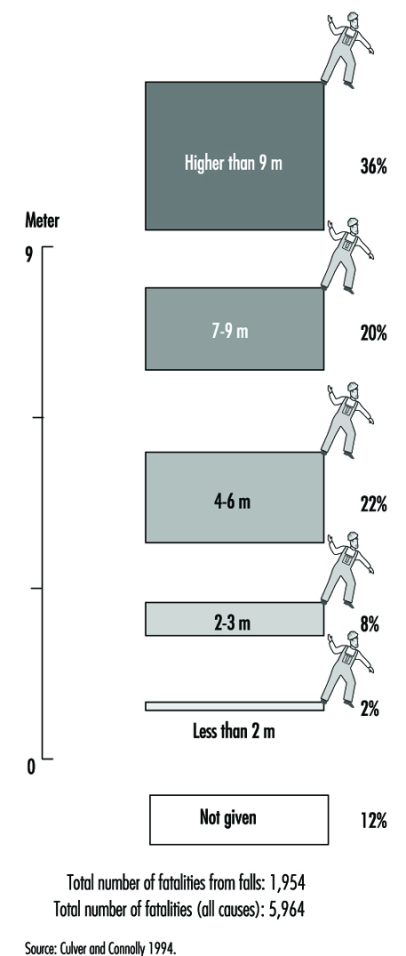
In many countries, regulations make fall protection mandatory when the worker is exposed to a fall of more than 3 m. The simplistic interpretation is that falls of less than 3 m are not dangerous. The 3-m limit is in fact the result of a social, political and practical consensus which says it is not mandatory to be protected against falls while working at the height of a single floor. Even if the 3-m legal limit for mandatory fall protection exists, fall protection should always be considered. The height of fall is not the sole factor explaining the severity of fall accidents and the fatalities due to falls; where and how the person falling came to rest must also be considered. This leads to analysis of the industrial sectors with higher incidence of falls from elevations.
Where Falls Occur
Falls from elevations are frequently associated with the construction industry because they account for a high percentage of all fatalities. For example, in the United States, 33% of all fatalities in construction are caused by falls from elevations; in the UK, the figure is 52%. Falls from elevations also occur in other industrial sectors. Mining and the manufacturing of transportation equipment have a high rate of falls from elevations. In Quebec, where many mines are steep, narrow-vein, underground mines, 20% of all accidents are falls from elevations. The manufacture, use and maintenance of transportation equipment such as airplanes, trucks and railroad cars are activities with a high rate of fall accidents (table 1). The ratio will vary from country to country depending on the level of industrialization, the climate, and so on; but falls from elevations do occur in all sectors with similar consequences.
Table 1. Falls from elevations: Quebec 1982-1987
Falls from elevations Falls from elevations in all accidents
per 1,000 workers
Construction 14.9 10.1%
Heavy industry 7.1 3.6%
Having taken into consideration the height of fall, the next important issue is how the fall is arrested. Falling into hot liquids, electrified rails or into a rock crusher could be fatal even if the height of fall is less than 3 m.
Causes of Falls
So far it has been shown that falls occur in all economic sectors, even if the height is less than 3 m. But why do humans fall? There are many human factors which can be involved in falling. A broad grouping of factors is both conceptually simple and useful in practice:
Opportunities to fall are determined by environmental factors and result in the most common type of fall, namely the tripping or slipping that result in falls from grade level. Other falling opportunities are related to activities above grade.
Liabilities to fall are one or more of the many acute and chronic diseases. The specific diseases associated with falling usually affect the nervous system, the circulatory system, the musculoskeletal system or a combination of these systems.
Tendencies to fall arise from the universal, intrinsic deteriorative changes that characterize normal ageing or senescence. In falling, the ability to maintain upright posture or postural stability is the function that fails as a result of combined tendencies, liabilities and opportunities.
Postural Stability
Falls are caused by the failure of postural stability to maintain a person in an upright position. Postural stability is a system consisting of many rapid adjustments to external, perturbing forces, especially gravity. These adjustments are largely reflex actions, subserved by a large number of reflex arcs, each with its sensory input, internal integrative connections, and motor output. Sensory inputs are: vision, the inner ear mechanisms that detect position in space, the somatosensory apparatus that detects pressure stimuli on the skin, and the position of the weight-bearing joints. It appears that visual perception plays a particularly important role. Very little is known about the normal, integrative structures and functions of the spinal cord or the brain. The motor output component of the reflex arc is muscular reaction.
Vision
The most important sensory input is vision. Two visual functions are related to postural stability and control of gait:
- the perception of what is vertical and what is horizontal is basic to spatial orientation
- the ability to detect and discriminate objects in cluttered environments.
Two other visual functions are important:
- the ability to stabilize the direction in which the eyes are pointed so as to stabilize the surrounding world while we are moving and immobilize a visual reference point
- the ability to fixate and pursue definite objects within the large field (“keep an eye on”); this function requires considerable attention and results in deterioration in the performance of any other simultaneous, attention-demanding tasks.
Causes of postural instability
The three sensory inputs are interactive and interrelated. The absence of one input—and/or the existence of false inputs—results in postural instability and even in falls. What could cause instability?
Vision
- the absence of vertical and horizontal references—for example, the connector at the top of a building
- the absence of stable visual references—for example, moving water under a bridge and moving clouds are not stable references
- the fixing a definite object for work purposes, which diminishes other visual functions, such as the ability to detect and discriminate objects that can cause tripping in a cluttered environment
- a moving object in a moving background or reference—for example, a structural steel component moved by a crane, with moving clouds as background and visual reference.
Inner ear
- having the person’s head upside down while the level equilibrium system is at its optimum performance horizontally
- travelling in pressurized aircraft
- very fast movement, as, for example, in a roller-coaster
- diseases.
Somatosensory apparatus (pressure stimuli on the skin and position of weight-bearing joints)
- standing on one foot
- numbed limbs from staying in a fixed position for a long period of time—for example, kneeling down
- stiff boots
- very cold limbs.
Motor output
- numbed limbs
- tired muscles
- diseases, injuries
- ageing, permanent or temporary disabilities
- bulky clothing.
Postural stability and gait control are very complex reflexes of the human being. Any perturbations of the inputs may cause falls. All perturbations described in this section are common in the workplace. Therefore, falling is somehow natural and prevention must therefore prevail.
Strategy for Fall Protection
As previously noted, the risks of falls are identifiable. Therefore, falls are preventable. Figure 2 shows a very common situation where a gauge must be read. The first illustration shows a traditional situation: a manometer is installed at the top of a tank without means of access In the second, the worker improvises a means of access by climbing on several boxes: a hazardous situation. In the third, the worker uses a ladder; this is an improvement. However, the ladder is not permanently fixed to the tank; it is therefore probable that the ladder may be in use elsewhere in the plant when a reading is required. A situation such as this is possible, with fall arrest equipment added to the ladder or the tank and with the worker wearing a full body harness and using a lanyard attached to an anchor. The fall-from-elevation hazard still exists.
Figure 2. Installations for reading a gauge
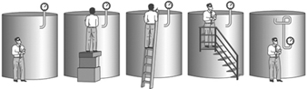
In the fourth illustration, an improved means of access is provided using a stairway, a platform and guardrails; the benefits are a reduction in the risk of falling and an increase in the ease of reading (comfort), thus reducing the duration of each reading and providing a stable work posture allowing for a more precise reading.
The correct solution is illustrated in the last illustration. During the design stage of the facilities, maintenance and operation activities were recognized. The gauge was installed so that it could be read at ground level. No falls from elevations are possible: therefore, the hazard is eliminated.
This strategy puts the emphasis on the prevention of falls by using the proper means of access (e.g., scaffolds, ladders, stairways) (Bouchard 1991). If the fall cannot be prevented, fall arrest systems must be used (figure 3). To be effective, fall arrest systems must be planned. The anchorage point is a key factor and must be pre-engineered. Fall arrest systems must be efficient, reliable and comfortable; two examples are given in Arteau, Lan and Corbeil (to be published) and Lan, Arteau and Corbeil (to be published). Examples of typical fall prevention and fall arrest systems are given in table 2. Fall arrest systems and components are detailed in Sulowski 1991.
Figure 3. Fall prevention strategy
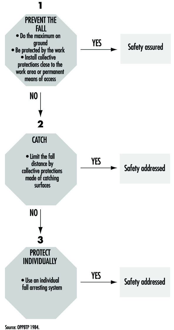
Table 2. Typical fall prevention and fall arrest systems
|
Fall prevention systems |
Fall arrest systems |
|
|
Collective protection |
Guardrails Railings |
Safety net |
|
Individual protection |
Travel restricting system (TRS) |
Harness, lanyard, energy absorber anchorage, etc. |
The emphasis on prevention is not an ideological choice, but rather a practical choice. Table 3 shows the differences between fall prevention and fall arrest, the traditional PPE solution.
Table 3. Differences between fall prevention and fall arrest
|
Prevention |
Arrest |
|
|
Fall occurrence |
No |
Yes |
|
Typical equipment |
Guardrails |
Harness, lanyard, energy absorber and anchorage (fall arrest system) |
|
Design load (force) |
1 to 1.5 kN applied horizontally and 0.45 kN applied vertically—both at any point on the upper rail |
Minimum breaking strength of the anchorage point 18 to 22 kN |
|
Loading |
Static |
Dynamic |
For the employer and the designer, it is easier to build fall prevention systems because their minimum breaking strength requirements are 10 to 20 times less than those of fall arrest systems. For example, the minimum breaking strength requirement of a guard rail is around 1 kN, the weight of a large man, and the minimum breaking strength requirement of the anchorage point of an individual fall arrest system could be 20 kN, the weight of two small cars or 1 cubic metre of concrete. With prevention, the fall does not occur, so the risk of injury does not exist. With fall arrest, the fall does occur and even if arrested, a residual risk of injury exists.
Rollover
Tractors and other mobile machinery in agricultural, forestry, construction and mining work, as well as materials handling, can give rise to serious hazards when the vehicles roll over sideways, tip over forwards or rear over backwards. The risks are heightened in the case of wheeled tractors with high centres of gravity. Other vehicles that present a hazard of rollover are crawler tractors, loaders, cranes, fruit-pickers, dozers, dumpers, scrapers and graders. These accidents usually happen too fast for drivers and passengers to get clear of the equipment, and they can become trapped under the vehicle. For example, tractors with high centres of gravity have considerable likelihood of rollover (and narrow tractors have even less stability than wide ones). A mercury engine cut-off switch to shut off power upon sensing lateral movement was introduced on tractors but was proven too slow to cope with the dynamic forces generated in the rollover movement (Springfeldt 1993). Therefore the safety device was abandoned.
The fact that such equipment often is used on sloping or uneven ground or on soft earth, and sometimes in close proximity to ditches, trenches or excavations, is an important contributing cause to rollover. If auxiliary equipment is attached high up on a tractor, the probability of rearing over backwards in climbing a slope (or tipping over forwards when descending) increases. Furthermore, a tractor can roll over because of the loss of control due to the pressure exerted by tractor-drawn equipment (e.g., when the carriage moves downwards on a slope and the attached equipment is not braked and over-runs the tractor). Special hazards arise when tractors are used as tow vehicles, particularly if the tow hook on the tractor is placed on a higher level than the wheel axle.
History
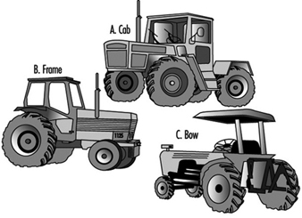
Notice of the rollover problem was taken on the national level in certain countries where many fatal rollovers occurred. In Sweden and New Zealand, development and testing of rollover protective structures (ROPS) on tractors (figure 1) already were in progress in the 1950s, but this work was followed up by regulations only on the part of the Swedish authorities; these regulations were effective from the year 1959 (Springfeldt 1993).
Figure 1. Usual types of ROPS on tractors
Proposed regulations prescribing ROPS for tractors were met by resistance in the agricultural sector in several countries. Strong opposition was mounted against plans requiring employers to install ROPS on existing tractors, and even against the proposal that only new tractors be equipped by the manufacturers with ROPS. Eventually many countries successfully mandated ROPS for new tractors, and later on some countries were able to require ROPS be retrofitted on old tractors as well. International standards concerning tractors and earth-moving machinery, including testing standards for ROPS, contributed to more reliable designs. Tractors were designed and manufactured with lower centres of gravity and lower-placed tow hooks. Four-wheel drive has reduced the risk of rollover. But the proportion of tractors with ROPS in countries with many old tractors and without mandates for retrofitting of ROPS is still rather low.
Investigations
Rollover accidents, particularly those involving tractors, have been studied by researchers in many countries. However, there are no centralized international statistics with respect to the number of accidents caused by the types of mobile machinery reviewed in this article. Available statistics at the national level nevertheless show that the number is high, especially in agriculture. According to a Scottish report of tractor rollover accidents in the period 1968–1976, 85% of the tractors involved had equipment attached at the time of the accident, and of these, half had trailed equipment and half had mounted equipment. Two-thirds of the tractor rollover accidents in the Scottish report occurred on slopes (Springfeldt 1993). It was later proved that the number of accidents would be reduced after the introduction of training for driving on slopes as well as the application of an instrument for measuring slope steepness combined with an indicator of safe slope limits.
In other investigations, New Zealand researchers observed that half of their fatal rollover accidents occurred on flat ground or on slight slopes, and only one-tenth occurred on steep slopes. On flat ground tractor drivers may be less attentive to rollover hazards, and they can misjudge the risk posed by ditches and uneven ground. Of the rollover fatalities in tractors in New Zealand in the period 1949–1980, 80% occurred in wheel tractors, and 20% with crawler tractors (Springfeldt 1993). Studies in Sweden and New Zealand showed that about 80% of the tractor rollover fatalities occurred when tractors rolled over sideways. Half of the tractors involved in the New Zealand fatalities had rolled 180°.
Studies of the correlation between rollover fatalities in West Germany and the model year of farm tractors (Springfeldt 1993) showed that 1 of 10,000 old, unprotected tractors manufactured before 1957 was involved in a rollover fatality. Of tractors with prescribed ROPS, manufactured in 1970 and later, 1 of 25,000 tractors was involved in a rollover fatality. Of fatal tractor rollovers in West Germany in the period 1980–1985, two-thirds of the victims were thrown from their protected area and then run over or hit by the tractor (Springfeldt 1993). Of nonfatal rollovers, one-quarter of the drivers were thrown from the driver’s seat but not run over. It is evident that the fatality risk increases if the driver is thrown out of the protected area (similar to automobile accidents). Most of the tractors involved had a two-pillar bow (figure 1 C) that does not prevent the driver from being thrown out. In a few cases the ROPS had been subject to breakage or strong deformation.
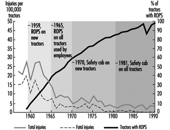
The relative frequencies of injuries per 100,000 tractors in different periods in some countries and the reduction of the fatality rate was calculated by Springfeldt (1993). The effectiveness of ROPS in diminishing injury in tractor rollover accidents has been proven in Sweden, where the number of fatalities per 100,000 tractors was reduced from approximately 17 to 0.3 over the period of three decades (1960–1990) (figure 2). At the end of the period it was estimated that about 98% of the tractors were fitted with ROPS, mainly in the form of a crushproof cab (figure 1 A). In Norway, fatalities were reduced from about 24 to 4 per 100,000 tractors during a similar period. However, worse results were achieved in Finland and New Zealand.
Figure 2. Injuries by rollovers per 100,000 tractors in Sweden between 1957 and 1990
Prevention of Injuries by Rollovers
The risk of rollover is greatest in the case of tractors; however, in agricultural and forest work there is little that can be done to prevent tractors from rolling over. By mounting ROPS on tractors and those types of earth-moving machinery with potential rollover hazards, the risk of personal injuries can be reduced, provided that the drivers remain on their seats during rollover events (Springfeldt 1993). The frequency of rollover fatalities depends largely on the proportion of protected machines in use and the types of ROPS used. A bow (figure 1 C) gives much less protection than a cab or a frame (Springfeldt 1993). The most effective structure is a crushproof cab, which allows the driver to stay inside, protected, during a rollover. (Another reason for choosing a cab is that it affords weather protection.) The most effective means of keeping the driver within the protection of the ROPS during a rollover is a seat-belt, provided that the driver uses the belt while operating the equipment. In some countries, there are information plates at the driver’s seat advising that the steering wheel be gripped in a rollover event. An additional safety measure is to design the driver’s cab or interior environment and the ROPS so as to prevent exposure to hazards such as sharp edges or protuberances.
In all countries, rollovers of mobile machinery, mainly tractors, are causing serious injures. There are, however, considerable differences among countries concerning technical specifications relating to machinery design, as well as administrative procedures for examinations, testing, inspections and marketing. The international diversity that characterizes safety efforts in this connection may be explained by considerations such as the following:
- whether there exist mandatory requirements for ROPS (in the form of regulations or legislation), or recommendations only, or no rules at all
- the need for rules for new machinery and rules applicable to older equipment
- the availability of inspection carried out by authorities and the existence of social pressure and cultural climate favourable to observance of safety rules; in many countries, the obedience to safety guidelines is not checked by inspection in agricultural work
- pressure from trade unions; however, it should be borne in mind that workers’ organizations have less influence on working conditions in agriculture than in other sectors, because there are many family farms in agriculture
- the type of ROPS used in the country
- information and understanding of the risks to which tractor drivers are exposed; practical problems often stand in the way of reaching farmers and forest workers for the purposes of information and education
- the geography of the country, especially where agricultural, forestry and road work is carried out.
Safety Regulations
The nature of rules governing requirements for ROPS and the degree of implementation of the rules in a country, has a strong influence on rollover accidents, especially fatal ones. With this in mind, the development of safer machinery has been abetted by directives, codes and standards issued by international and national organizations. Additionally, many countries have adopted rigorous prescriptions for ROPS which have resulted in a great reduction of rollover injuries.
European Economic Community
Beginning in 1974 the European Economic Community (EEC) issued directives concerning type-approval of wheeled agricultural and forestry tractors, and in 1977 issued further, special directives concerning ROPS, including their attachment to tractors (Springfeldt 1993; EEC 1974, 1977, 1979, 1982, 1987). The directives prescribe a procedure for type-approval and certification by manufacture of tractors, and ROPS must be reviewed by an EEC Type Approval Examination. The directives have won acceptance by all the member countries.
Some EEC directives concerning ROPS on tractors were repealed as of 31 December 1995 and replaced by the general machinery directive which applies to those sorts of machinery presenting hazards due to their mobility (EEC 1991). Wheeled tractors, as well as some earth-moving machinery with a capacity exceeding 15 kW (namely crawlers and wheel loaders, backhoe loaders, crawler tractors, scrapers, graders and articulated dumpers) must be fitted with a ROPS. In case of a rollover, the ROPS must offer the driver and operators an adequate deflection-limiting volume (i.e., space allowing movement of occupants’ bodies before contacting interior elements during an accident). It is the responsibility of the manufacturers or their authorized representatives to perform appropriate tests.
Organization for Economic Cooperation and Development
In 1973 and 1987 the Organization for Economic Cooperation and Development (OECD) approved standard codes for testing of tractors (Springfeldt 1993; OECD 1987). They give results of tests of tractors and describe the testing equipment and test conditions. The codes require testing of many machinery parts and functions, for instance the strength of ROPS. The OECD Tractor Codes describe a static and a dynamic method of testing ROPS on certain types of tractors. A ROPS may be designed solely to protect the driver in the event of tractor rollover. It must be retested for each model of tractor to which the ROPS is to be fitted. The Codes also require that it be possible to mount a weather protection for the driver onto the structure, of a more or less temporary nature. The Tractor Codes have been accepted by all OECD member bodies from 1988, but in practice the United States and Japan also accept ROPS that do not comply with the code requirements if safety belts are provided (Springfeldt 1993).
International Labour Organization
In 1965, the International Labour Organization (ILO) in its manual, Safety and Health in Agricultural Work, required that a cab or a frame of sufficient strength be adequately fixed to tractors in order to provide satisfactory protection for the driver and passengers inside the cab in case of tractor rollover (Springfeldt 1993; ILO 1965). According to ILO Codes of Practice, agricultural and forestry tractors should be provided with ROPS to protect the operator and any passenger in case of rollover, falling objects or displaced loads (ILO 1976).
The fitting of ROPS should not adversely affect
- access between the ground and driver’s position
- access to the tractor’s main controls
- the manoeuvrability of the tractor in cramped surroundings
- the attachment or use of any equipment that may be connected to the tractor
- the control and adjustment of associated equipment.
International and national standards
In 1981 the International Organization for Standardization (ISO) issued a standard for tractors and machinery for agriculture and forestry (ISO 1981). The standard describes a static test method for ROPS and sets forth acceptance conditions. The standard has been approved by the member bodies in 22 countries; however, Canada and the United States have expressed disapproval of the document on technical grounds. A Standard and Recommended Practice issued in 1974 by the Society of Automotive Engineers (SAE) in North America contains performance requirements for ROPS on wheeled agricultural tractors and industrial tractors used in construction, rubber-tired scrapers, front-end loaders, dozers, crawler loaders, and motor graders (SAE 1974 and 1975). The contents of the standard have been adopted as regulations in the United States and in the Canadian provinces of Alberta and British Columbia.
Rules and Compliance
OECD Codes and International Standards concern the design and construction of ROPS as well as the control of their strength, but lack the authority to require that this sort of protection be put into practice (OECD 1987; ISO 1981). The European Economic Community also proposed that tractors and earth-moving machinery be equipped with protection (EEC 1974-1987). The aim of the EEC directives is to achieve uniformity among national entities concerning the safety of new machinery at the manufacturing stage. The member countries are obliged to follow the directives and issue corresponding prescriptions. Starting in 1996, the member countries of the EEC intend to issue regulations requiring that new tractors and earth-moving machinery be fitted with ROPS.
In 1959, Sweden became the first country to require ROPS for new tractors (Springfeldt 1993). Corresponding requirements came into effect in Denmark and Finland ten years later. Later on, in the 1970s and 1980s, mandatory requirements for ROPS on new tractors became effective in Great Britain, West Germany, New Zealand, the United States, Spain, Norway, Switzerland and other countries. In all these countries except the United States, the rules were extended to old tractors some years later, but these rules were not always mandatory. In Sweden, all tractors must be equipped with a protective cab, a rule that in Great Britain applies only to all tractors used by agricultural workers (Springfeldt 1993). In Denmark, Norway and Finland, all tractors must be provided with at least a frame, while in the United States and the Australian states, bows are accepted. In the United States tractors must have seat-belts.
In the United States, materials-handling machinery that was manufactured before 1972 and is used in construction work must be equipped with ROPS which meet minimum performance standards (US Bureau of National Affairs 1975). The machines covered by the requirement include some scrapers, front-end loaders, dozers, crawler tractors, loaders, and motor graders. Retrofitting was carried out of ROPS on machines manufactured about three years earlier.
Summary
In countries with mandatory requirements for ROPS for new tractors and retrofitting of ROPS on old tractors, there has been a decrease of rollover injuries, especially fatal ones. It is evident that a crushproof cab is the most effective type of ROPS. A bow gives poor protection in case of rollover. Many countries have prescribed effective ROPS at least on new tractors and as of 1996 on earth-moving machines. In spite of this fact some authorities seem to accept types of ROPS that do not comply with such requirements as have been promulgated by the OECD and the ISO. It is expected that a more general harmonization of the rules governing ROPS will be accomplished gradually all over the world, including the developing countries.
Technical Requirements for Safety-Related Systems Based on Electrical, Electronic and Programmable Electronic Devices
Machinery, process plants and other equipment can, if they malfunction, present risks from hazardous events such as fires, explosions, radiation overdoses and moving parts. One of the ways such plants, equipment and machinery can malfunction is from failures of electro-mechanical, electronic and programmable electronic (E/E/PE) devices used in the design of their control or safety systems. These failures can arise either from physical faults in the device (e.g., from wear and tear occurring randomly in time (random hardware failures)); or from systematic faults (e.g., errors made in the specification and design of a system that cause it to fail due to (1) some particular combination of inputs, (2) some environmental condition (3) incorrect or incomplete inputs from sensors, (4) incomplete or erroneous data entry by operators, and (5) potential systematic faults due to poor interface design).
Safety-Related Systems Failures
This article covers the functional safety of safety-related control systems, and considers the hardware and software technical requirements necessary to achieve the required safety integrity. The overall approach is in accordance with the proposed International Electrotechnical Commission Standard IEC 1508, Parts 2 and 3 (IEC 1993). The overall goal of draft international standard IEC 1508, Functional Safety: Safety-Related Systems, is to ensure that plant and equipment can be safety automated. A key objective in the development of the proposed international standard is to prevent or minimize the frequency of:
- failures of control systems triggering other events which in turn could lead to danger (e.g., control system fails, control is lost, process goes out of control resulting in a fire, release of toxic materials, etc.)
- failures in alarm and monitoring systems so that operators are not given information in a form that can be quickly identified and understood in order to carry out the necessary emergency actions
- undetected failures in protection systems, making them unavailable when needed for a safety action (e.g., a failed input card in an emergency shut-down system).
The article “Electrical, electronic and programmable electronic safety-related systems” sets out the general safety management approach embodied within Part 1 of IEC 1508 for assuring the safety of control and protection systems that are important to safety. This article describes the overall conceptual engineering design that is needed to reduce the risk of an accident to an acceptable level, including the role of any control or protection systems based on E/E/PE technology.
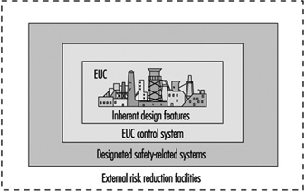
In figure 1, the risk from the equipment, process plant or machine (generally referred to as equipment under control (EUC) without protective devices) is marked at one end of the EUC Risk Scale, and the target level of risk that is needed to meet the required level of safety is at the other end. In between is shown the combination of safety-related systems and external risk reduction facilities needed to make up the required risk reduction. These can be of various types—mechanical (e.g., pressure relief valves), hydraulic, pneumatic, physical, as well as E/E/PE systems. Figure 2 emphasizes the role of each safety layer in protecting the EUC as the accident progresses.
Figure 1. Risk reduction: General concepts

Figure 2. Overall model: Protection layers
Provided that a hazard and risk analysis has been performed on the EUC as required in Part 1 of IEC 1508, the overall conceptual design for safety has been established and therefore the required functions and Safety Integrity Level (SIL) target for any E/E/PE control or protection system have been defined. The Safety Integrity Level target is defined with respect to a Target Failure Measure (see table 1).
Table 1. Safety Integrity Levels for protection systems: Target failure measures
Safety integrity Level Demand mode of operation (Probability of failure to perform its design function on demand)
4 10-5 ≤ × 10-4
3 10-4 ≤ × 10-3
2 10-3 ≤ × 10-2
1 10-2 ≤ × 10-1
Protection Systems
This paper outlines the technical requirements that the designer of an E/E/PE safety-related system should consider to satisfy the required Safety Integrity Level target. The focus is on a typical protection system utilizing programmable electronics in order to allow for a more in-depth discussion of the key issues with little loss in generality. A typical protection system is shown in figure 3, which depicts a single channel safety system with a secondary switch-off activated via a diagnostic device. In normal operation the unsafe condition of the EUC (e.g., overspeed in a machine, high temperature in a chemical plant) will be detected by the sensor and transmitted to the programmable electronics, which will command the actuators (via the output relays) to put the system into a safe state (e.g., removing power to electric motor of the machine, opening a valve to relieve pressure).
Figure 3. Typical protection system
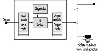
But what if there are failures in the protection system components? This is the function of the secondary switch-off, which is activated by the diagnostic (self-checking) feature of this design. However, the system is not completely fail-safe, as the design has only a certain probability of being available when being asked to carry out its safety function (it has a certain probability of failure on demand or a certain Safety Integrity Level). For example, the above design might be able to detect and tolerate certain types of output card failure, but it would not be able to withstand a failure of the input card. Therefore, its safety integrity will be much lower than that of a design with a higher-reliability input card, or improved diagnostics, or some combination of these.
There are other possible causes of card failures, including “traditional” physical faults in the hardware, systematic faults including errors in the requirements specification, implementation faults in the software and inadequate protection against environmental conditions (e.g., humidity). The diagnostics in this single-channel design may not cover all these types of faults, and therefore this will limit the Safety Integrity Level achieved in practice. (Coverage is a measure of the percentage of faults that a design can detect and handle safely.)
Technical Requirements
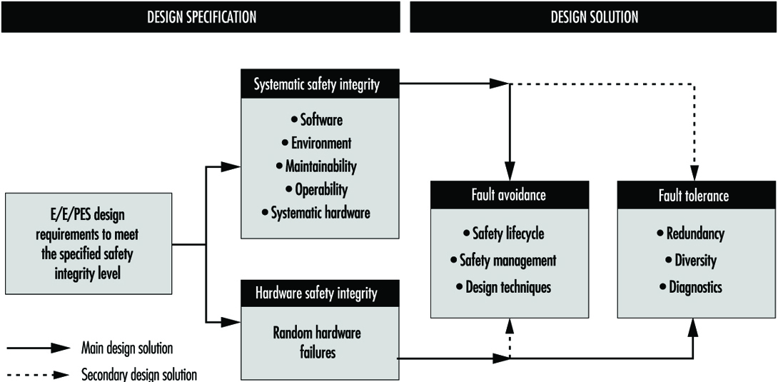
Parts 2 and 3 of draft IEC 1508 provide a framework for identifying the various potential causes of failure in hardware and software and for selecting design features that overcome those potential causes of failure appropriate to the required Safety Integrity Level of the safety-related system. For example, the overall technical approach for the protection system in figure 3 is shown in figure 4. The figure indicates the two basic strategies for overcoming faults and failures: (1) fault avoidance, where care is taken in to prevent faults being created; and (2) fault tolerance, where the design is created specifically to tolerate specified faults. The single-channel system mentioned above is an example of a (limited) fault tolerant design where diagnostics are used to detect certain faults and put the system into a safe state before a dangerous failure can occur.
Figure 4. Design specification: Design solution
Fault avoidance
Fault avoidance attempts to prevent faults being introduced into a system. The main approach is to use a systematic method of managing the project so that safety is treated as a definable and manageable quality of a system, during design and then subsequently during operation and maintenance. The approach, which is similar to quality assurance, is based on the concept of feedback and involves: (1) planning (defining safety objectives, identifying the ways and means to achieve the objectives); (2) measuring achievement against the plan during implementation and (3) applying feedback to correct for any deviations. Design reviews are a good example of a fault avoidance technique. In IEC 1508 this “quality” approach to fault avoidance is facilitated by the requirements to use a safety lifecycle and employ safety management procedures for both hardware and software. For the latter, these often manifest themselves as software quality assurance procedures such as those described in ISO 9000-3 (1990).
In addition, Parts 2 and 3 of IEC 1508 (concerning hardware and software, respectively) grade certain techniques or measures that are considered useful for fault avoidance during the various safety lifecycle phases. Table 2 gives an example from Part 3 for the design and development phase of software. The designer would use the table to assist in the selection of fault avoidance techniques, depending on the required Safety Integrity Level. With each technique or measure in the tables there is a recommendation for each Safety Integrity Level, 1 to 4. The range of recommendations covers Highly Recommended (HR), Recommended (R), Neutral—neither for or against (—) and Not Recommended (NR).
Table 2. Software design and development
|
Technique/measure |
SIL 1 |
SIL 2 |
SIL 3 |
SIL 4 |
|
1. Formal methods including, for example, CCS, CSP, HOL, LOTOS |
— |
R |
R |
HR |
|
2. Semi-formal methods |
HR |
HR |
HR |
HR |
|
3. Structured. Methodology including, for example, JSD, MASCOT, SADT, SSADM and YOURDON |
HR |
HR |
HR |
HR |
|
4. Modular approach |
HR |
HR |
HR |
HR |
|
5. Design and coding standards |
R |
HR |
HR |
HR |
HR = highly recommended; R = recommended; NR = not recommended;— = neutral: the technique/measure is neither for or against the SIL.
Note: a numbered technique/measure shall be selected according to the safety integrity level.
Fault tolerance
IEC 1508 requires increasing levels of fault tolerance as the safety integrity target increases. The standard recognizes, however, that fault tolerance is more important when systems (and the components that make up those systems) are complex (designated as Type B in IEC 1508). For less complex, “well proven” systems, the degree of fault tolerance can be relaxed.
Tolerance against random hardware faults
Table 3 shows the requirements for fault tolerance against random hardware failures in complex hardware components (e.g., microprocessors) when used in a protection system such as is shown in figure 3. The designer may need to consider an appropriate combination of diagnostics, fault tolerance and manual proof checks to overcome this class of fault, depending on the required Safety Integrity Level.
Table 3. Safety Integrity Level - Fault requirements for Type B components1
1 Safety-related undetected faults shall be detected by the proof check.
2 For components without on-line medium diagnostic coverage, the system shall be able to perform the safety function in the presence of a single fault. Safety-related undetected faults shall be detected by the proof check.
3 For components with on-line high diagnostic coverage, the system shall be able to perform the safety function in the presence of a single fault. For components without on-line high diagnostic coverage, the system shall be able to perform the safety function in the presence of two faults. Safety-related undetected faults shall be detected by the proof check.
4 The components shall be able to perform the safety function in the presence of two faults. Faults shall be detected with on-line high diagnostic coverage. Safety-related undetected faults shall be detected by the proof check. Quantitative hardware analysis shall be based on worst-case assumptions.
1Components whose failure modes are not well defined or testable, or for which there are poor failure data from field experience (e.g., programmable electronic components).
IEC 1508 aids the designer by providing design specification tables (see table 4) with design parameters indexed against the Safety Integrity Level for a number of commonly used protection system architectures.
Table 4. Requirements for Safety Integrity Level 2 - Programmable electronic system architectures for protection systems
|
PE system configuration |
Diagnostic coverage per channel |
Off-line proof test Interval (TI) |
Mean time to spurious trip |
|
Single PE, Single I/O, Ext. WD |
High |
6 months |
1.6 years |
|
Dual PE, Single I/O |
High |
6 months |
10 years |
|
Dual PE, Dual I/O, 2oo2 |
High |
3 months |
1,281 years |
|
Dual PE, Dual I/O, 1oo2 |
None |
2 months |
1.4 years |
|
Dual PE, Dual I/O, 1oo2 |
Low |
5 months |
1.0 years |
|
Dual PE, Dual I/O, 1oo2 |
Medium |
18 months |
0.8 years |
|
Dual PE, Dual I/O, 1oo2 |
High |
36 months |
0.8 years |
|
Dual PE, Dual I/O, 1oo2D |
None |
2 months |
1.9 years |
|
Dual PE, Dual I/O, 1oo2D |
Low |
4 months |
4.7 years |
|
Dual PE, Dual I/O, 1oo2D |
Medium |
18 months |
18 years |
|
Dual PE, Dual I/O, 1oo2D |
High |
48+ months |
168 years |
|
Triple PE, Triple I/O, IPC, 2oo3 |
None |
1 month |
20 years |
|
Triple PE, Triple I/O, IPC, 2oo3 |
Low |
3 months |
25 years |
|
Triple PE, Triple I/O, IPC, 2oo3 |
Medium |
12 months |
30 years |
|
Triple PE, Triple I/O, IPC, 2oo3 |
High |
48+ months |
168 years |
The first column of the table represents architectures with varying degrees of fault tolerance. In general, architectures placed near the bottom of the table have a higher degree of fault tolerance than those near the top. A 1oo2 (one out of two) system is able to withstand any one fault, as can 2oo3.
The second column describes the percentage coverage of any internal diagnostics. The higher the level of the diagnostics, the more faults will be trapped. In a protection system this is important because, provided the faulty component (e.g., an input card) is repaired within a reasonable time (often 8 hours), there is little loss in functional safety. (Note: this would not be the case for a continuous control system, because any fault is likely to cause an immediate unsafe condition and the potential for an incident.)
The third column shows the interval between proof tests. These are special tests that are required to be carried out to thoroughly exercise the protection system to ensure that there are no latent faults. Typically these are carried out by the equipment vendor during plant shutdown periods.
The fourth column shows the spurious trip rate. A spurious trip is one that causes the plant or equipment to shut down when there is no process deviation. The price for safety is often a higher spurious trip rate. A simple redundant protection system—1oo2—has, with all other design factors unchanged, a higher Safety Integrity Level but also a higher spurious trip rate than a single-channel (1oo1) system.
If one of the architectures in the table is not being used or if the designer wants to carry out a more fundamental analysis, then IEC 1508 allows this alternative. Reliability engineering techniques such as Markov modelling can then be used to calculate the hardware element of the Safety Integrity Level (Johnson 1989; Goble 1992).
Tolerance against systematic and common cause failures
This class of failure is very important in safety systems and is the limiting factor on the achievement of safety integrity. In a redundant system a component or subsystem, or even the whole system, is duplicated to achieve a high reliability from lower-reliability parts. Reliability improvement occurs because, statistically, the chance of two systems failing simultaneously by random faults will be the product of the reliabilities of the individual systems, and hence much lower. On the other hand, systematic and common cause faults cause redundant systems to fail coincidentally when, for example, a specification error in the software leads the duplicated parts to fail at the same time. Another example would be the failure of a common power supply to a redundant system.
IEC 1508 provides tables of engineering techniques ranked against the Safety Integrity Level considered effective in providing protection against systematic and common cause failures.
Examples of techniques providing defences against systematic failures are diversity and analytical redundancy. The basis of diversity is that if a designer implements a second channel in a redundant system using a different technology or software language, then faults in the redundant channels can be regarded as independent (i.e., a low probability of coincidental failure). However, particularly in the area of software-based systems, there is some suggestion that this technique may not be effective, as most mistakes are in the specification. Analytical redundancy attempts to exploit redundant information in the plant or machine to identify faults. For the other causes of systematic failure—for example, external stresses—the standard provides tables giving advice on good engineering practices (e.g., separation of signal and power cables) indexed against Safety Integrity Level.
Conclusions
Computer-based systems offer many advantages—not only economic, but also the potential for improving safety. However, the attention to detail required to realize this potential is significantly greater than is the case using conventional system components. This article has outlined the main technical requirements that a designer needs to take into account to successfully exploit this technology.
Electrical, Electronic and Programmable Electronic Safety-Related Control Systems
This article discusses the design and implementation of safety- related control systems which deal with all types of electrical, electronic and programmable-electronic systems (including computer-based systems). The overall approach is in accordance with proposed International Electrotechnical Commission (IEC) Standard 1508 (Functional Safety: Safety-Related
Systems) (IEC 1993).
Background
During the 1980s, computer-based systems—generically referred to as programmable electronic systems (PESs)—were increasingly being used to carry out safety functions. The primary driving forces behind this trend were (1) improved functionality and economic benefits (particularly considering the total life cycle of the device or system) and (2) the particular benefit of certain designs, which could be realized only when computer technology was used. During the early introduction of computer-based systems a number of findings were made:
- The introduction of computer control was poorly thought out and planned.
- Inadequate safety requirements were specified.
- Inadequate procedures were developed with respect to the validation of software.
- Evidence of poor workmanship was disclosed with respect to the standard of plant installation.
- Inadequate documentation was generated and not adequately validated with respect to what was actually in the plant (as distinct from what was thought to be in the plant).
- Less than fully effective operation and maintenance procedures had been established.
- There was evidently justified concern about the competence of persons to perform the duties required of them.
In order to solve these problems, several bodies published or began developing guidelines to enable the safe exploitation of PES technology. In the United Kingdom, the Health and Safety Executive (HSE) developed guidelines for programmable electronic systems used for safety-related applications, and in Germany, a draft standard (DIN 1990) was published. Within the European Community, an important element in the work on harmonized European Standards concerned with safety-related control systems (including those employing PESs) was started in connection with the requirements of the Machinery Directive. In the United States, the Instrument Society of America (ISA) has produced a standard on PESs for use in the process industries, and the Center for Chemical Process Safety (CCPS), a directorate of the American Institute of Chemical Engineers, has produced guidelines for the chemical process sector.
A major standards initiative is currently taking place within the IEC to develop a generically based international standard for electrical, electronic and programmable electronic (E/E/PES) safety-related systems that could be used by the many applications sectors, including the process, medical, transport and machinery sectors. The proposed IEC international standard comprises seven Parts under the general title IEC 1508. Functional safety of electrical/electronic/programmable electronic safety-related systems. The various Parts are as follows:
- Part 1.General requirements
- Part 2.Requirements for electrical, electronic and programmable electronic systems
- Part 3.Software requirements
- Part 4.Definitions
- Part 5.Examples of methods for the determination of safety integrity levels
- Part 6.Guidelines on the application of Parts 2 and 3
- Part 7.Overview of techniques and measures.
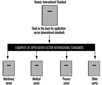
When finalized, this generically based International Standard will constitute an IEC basic safety publication covering functional safety for electrical, electronic and programmable electronic safety-related systems and will have implications for all IEC standards, covering all application sectors as regards the future design and use of electrical/electronic/programmable electronic safety-related systems. A major objective of the proposed standard is to facilitate the development of standards for the various sectors (see figure 1).
Figure 1. Generic and application sector standards
PES Benefits and Problems
The adoption of PESs for safety purposes had many potential advantages, but it was recognized that these would be achieved only if appropriate design and assessment methodologies were used, because: (1) many of the features of PESs do not enable the safety integrity (that is, the safety performance of the systems carrying out the required safety functions) to be predicted with the same degree of confidence that has traditionally been available for less complex hardware-based (“hardwired”) systems; (2) it was recognized that while testing was necessary for complex systems, it was not sufficient on its own. This meant that even if the PES was implementing relatively simple safety functions, the level of complexity of the programmable electronics was significantly greater than that of the hardwired systems they were replacing; and (3) this rise in complexity meant that the design and assessment methodologies had to be given much more consideration than previously, and that the level of personal competence required to achieve adequate levels of performance of the safety-related systems was subsequently greater.
The benefits of computer-based PESs include the following:
- the ability to perform on-line diagnostic proof checks on critical components at a frequency significantly higher than would otherwise be the case
- the potential to provide sophisticated safety interlocks
- the ability to provide diagnostic functions and condition monitoring which can be used to analyse and report on the performance of plant and machinery in real time
- the capability of comparing actual conditions of the plant with “ideal” model conditions
- the potential to provide better information to operators and hence to improve decision-making affecting safety
- the use of advanced control strategies to enable human operators to be located remotely from hazardous or hostile environments
- the ability to diagnose the control system from a remote location.
The use of computer-based systems in safety-related applications creates a number of problems which need to be adequately addressed, such as the following:
- The failure modes are complex and not always predictable.
- Testing the computer is necessary but is not sufficient in itself to establish that the safety functions will be performed with the degree of certainty required for the application.
- Microprocessors may have subtle variations between different batches, and therefore different batches may display different behaviour.
- Unprotected computer-based systems are particularly susceptible to electrical interference (radiated interference; electrical “spikes” in the mains supplies, electrostatic discharges, etc.).
- It is difficult and often impossible to quantify the probability of failure of complex safety-related systems incorporating software. Because no method of quantification has been widely accepted, software assurance has been based on procedures and standards which describe the methods to be used in the design, implementation and maintenance of the software.
Safety Systems under Consideration
The types of safety-related systems under consideration are electrical, electronic and programmable electronic systems (E/E/PESs). The system includes all elements, particularly signals extending from sensors or from other input devices on the equipment under control, and transmitted via data highways or other communication paths to the actuators or other output devices (see figure 2).
Figure 2. Electrical, electronic and programmable electronic system (E/E/PES)
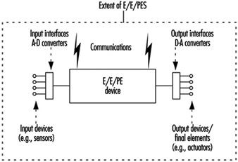
The term electrical, electronic and programmable electronic device has been used to encompass a wide variety of devices and covers the following three chief classes:
- electrical devices such as electro-mechanical relays
- electronic devices such as solid state electronic instruments and logic systems
- programmable electronic devices, which includes a wide variety of computer-based systems such as the following:
- microprocessors
- micro-controllers
- programmable controllers (PCs)
- application-specific integrated circuits (ASICs)
- programmable logic controllers (PLCs)
- other computer-based devices (e.g., “smart” sensors, transmitters and actuators).
By definition, a safety-related system serves two purposes:
- It implements the required safety functions necessary to achieve a safe state for the equipment under control or maintains a safe state for the equipment under control. The safety-related system must perform those safety functions that are specified in the safety functions requirements specification for the system. For example, the safety functions requirements specification may state that when the temperature reaches a certain value x, valve y shall open to allow water to enter the vessel.
- It achieves, on its own or with other safety-related systems, the necessary level of safety integrity for the implementation of the required safety functions. The safety functions must be performed by the safety-related systems with the degree of confidence appropriate to the application in order to achieve the required level of safety for the equipment under control.
This concept is illustrated in figure 3.
Figure 3. Key features of safety-related systems
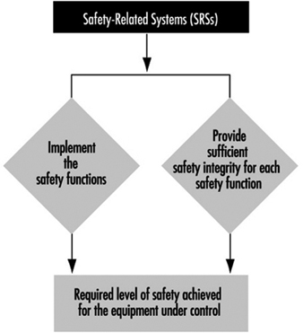
System Failures
In order to ensure safe operation of E/E/PES safety-related systems, it is necessary to recognize the various possible causes of safety-related system failure and to ensure that adequate precautions are taken against each. Failures are classified into two categories, as illustrated in figure 4.
Figure 4. Failure categories
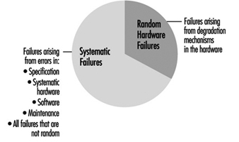
- Random hardware failures are those failures which result from a variety of normal degradation mechanisms in the hardware. There are many such mechanisms occurring at different rates in different components, and since manufacturing tolerances cause components to fail on account of these mechanisms after different times in operation, failures of a total item of equipment comprising many components occur at unpredictable (random) times. Measures of system reliability, such as the mean time between failures (MTBF), are valuable but are usually concerned only with random hardware failures and do not include systematic failures.
- Systematic failures arise from errors in the design, construction or use of a system which cause it to fail under some particular combination of inputs or under some particular environmental condition. If a system failure occurs when a particular set of circumstances arises, then whenever those circumstances arise in the future there will always be a system failure. Any failure of a safety-related system which does not arise from a random hardware failure is, by definition, a systematic failure. Systematic failures, in the context of E/E/PES safety-related systems, include:
- systematic failures due to errors or omissions in the safety functions requirements specification
- systematic failures due to errors in the design, manufacture, installation or operation of the hardware. These would include failures arising from environmental causes and human (e.g., operator) error
- systematic failures due to faults in the software
- systematic failures due to maintenance and modification errors.
Protection of Safety-Related Systems
The terms that are used to indicate the precautionary measures required by a safety-related system to protect against random hardware failures and systematic failures are hardware safety integrity measures and systematic safety integrity measures respectively. Precautionary measures that a safety-related system can bring to bear against both random hardware failures and systematic failures are termed safety integrity. These concepts are illustrated in figure 5.
Figure 5. Safety performance terms
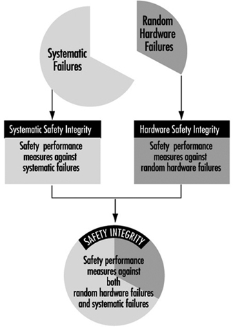
Within the proposed international standard IEC 1508 there are four levels of safety integrity, denoted Safety Integrity Levels 1, 2, 3 and 4. Safety Integrity Level 1 is the lowest safety integrity level and Safety Integrity Level 4 is the highest. The Safety Integrity Level (whether 1, 2, 3 or 4) for the safety-related system will depend upon the importance of the role the safety-related system is playing in achieving the required level of safety for the equipment under control. Several safety-related systems may be necessary—some of which may be based on pneumatic or hydraulic technology.
Design of Safety-Related Systems
A recent analysis of 34 incidents involving control systems (HSE) found that 60% of all cases of failure had been “built in” before the safety-related control system had been put into use (figure 7). Consideration of all the safety life cycle phases is necessary if adequate safety-related systems are to be produced.
Figure 7. Primary cause (by phase) of control system failure
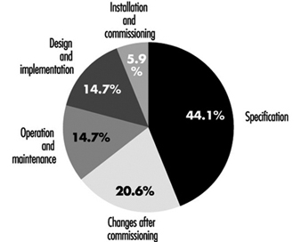
Functional safety of safety-related systems depends not only on ensuring that the technical requirements are properly specified but also in ensuring that the technical requirements are effectively implemented and that the initial design integrity is maintained throughout the life of the equipment. This can be realized only if an effective safety management system is in place and the people involved in any activity are competent with respect to the duties they have to perform. Particularly when complex safety-related systems are involved, it is essential that an adequate safety management system is in place. This leads to a strategy that ensures the following:
- An effective safety management system is in place.
- The technical requirements that are specified for the E/E/PES safety-related systems are sufficient to deal with both random hardware and systematic failure causes.
- The competence of the people involved is adequate for the duties they have to perform.
In order to address all the relevant technical requirements of functional safety in a systematic manner, the concept of the Safety Lifecycle has been developed. A simplified version of the Safety Lifecycle in the emerging international standard IEC 1508 is shown in figure 8. The key phases of the Safety Lifecycle are:
Figure 8. Role of the Safety Lifecycle in achieving functional safety
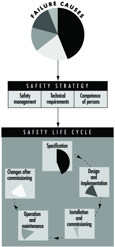
- specification
- design and implementation
- installation and commissioning
- operation and maintenance
- changes after commissioning.
Level of Safety
The design strategy for the achievement of adequate levels of safety integrity for the safety-related systems is illustrated in figure 9 and figure 10. A safety integrity level is based on the role the safety-related system is playing in the achievement of the overall level of safety for the equipment under control. The safety integrity level specifies the precautions that need to be taken into account in the design against both random hardware and systematic failures.
Figure 9. Role of safety integrity levels in the design process
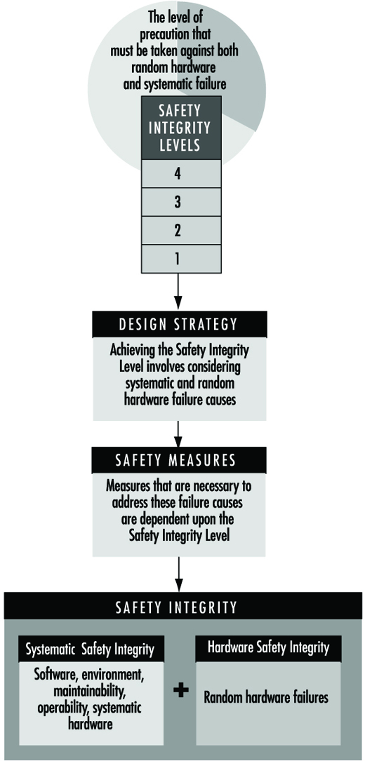
Figure 10. Role of the Safety Lifecycle in the specification and design process
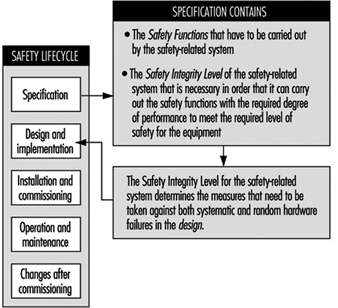
The concept of safety and level of safety applies to the equipment under control. The concept of functional safety applies to the safety-related systems. Functional safety for the safety-related systems has to be achieved if an adequate level of safety is to be achieved for the equipment that is giving rise to the hazard. The specified level of safety for a specific situation is a key factor in the safety integrity requirements specification for the safety-related systems.
The required level of safety will depend upon many factors—for example, the severity of injury, the number of people exposed to danger, the frequency with which people are exposed to danger and the duration of the exposure. Important factors will be the perception and views of those exposed to the hazardous event. In arriving at what constitutes an appropriate level of safety for a specific application, a number of inputs are considered, which include the following:
- legal requirements relevant to the specific application
- guidelines from the appropriate safety regulatory authority
- discussions and agreements with the different parties involved in the application
- industry standards
- national and international standards
- the best independent industrial, expert and scientific advice.
Summary
When designing and using safety-related systems, it must be remembered that it is the equipment under control that creates the potential hazard. The safety-related systems are designed to reduce the frequency (or probability) of the hazardous event and/or the consequences of the hazardous event. Once the level of safety has been set for the equipment, the safety integrity level for the safety-related system can be determined, and it is the safety integrity level that allows the designer to specify the precautions that need to be built into the design to be deployed against both random hardware and systematic failures.
Environmental Issues
Many of the processes described in the articles in this chapter can generate hazardous waste such as solvents, acids, alkalis, formaldehyde and so forth.
In dry cleaning, there has been concern about perchloroethylene vapours polluting the air of apartments above the dry-cleaning shops. The installation of machinery for purification and recovery of solvent vapours, the centralization of dry cleaning (using local shops just as drop-off and pickup places) and the development of wet cleaning methods that minimize solvent use are all methods that can minimize these problems.
Funeral parlours using embalming generate both chemical hazardous waste (e.g., formaldehyde) and biological hazardous waste (blood and blood-containing materials). Most countries where embalming is practised require these to be disposed of as hazardous waste. In crematoria, airborne mercury contamination can result from mercury amalgam fillings in teeth.
Most cosmetology shops that generate chemical waste pour it down the drain or place containers with residues in the trash. This is also true of cleaning personnel, both in homes and in institutions, who can generate waste in the form of solvents, acids and other cleaning products containing hazardous chemicals. The existence of many generators individually producing small amounts of waste creates a control problem; focused and standard control technologies are not easily implemented in these cases. For example, even in large institutions like hospitals, the cleaning chemicals are used in small amounts throughout the building, with cleaning chemicals often stored at many locations.
There are several solutions to this problem. One is the ongoing development of less hazardous substitutes, especially the replacement of solvents with water-based products. Another solution is the adoption of procedures to ensure that only the amounts of products needed for the near future are purchased, to avoid the accumulation of old products that must be disposed of. Using all the product in a container before discarding it in the trash can reduce the pollution from that source. In recent years, some countries, like the United States and Canada, have established local household hazardous waste programmes where waste such as solvents and cleaning products can be taken to central collection points that will accept the hazardous waste free of charge and dispose of it according to proper procedures.
Domestic Workers
General Profile
Domestic work is characterized by labour for another family within their home. The term domestic workers should not be confused with homemakers and housewives, who work in their own home, or housekeepers, who work in institutions such as a hospital or school. The position of employment within a home is a unique and often isolated work environment. The position of domestic worker is almost always considered menial or inferior to the family for which they are employed. Indeed in the past, domestic work was sometimes done by slaves or indentured or bonded servants. Some of the job titles today for domestic workers include: servant, maid, housekeeper, au pair and nanny. While domestic workers can be either female or male, female workers are both much more commonly employed and most often paid less than males. Domestic workers are customarily immigrants or members of ethnic, national or religious minorities of the country of employment.
One should distinguish between domestic workers who are employed as live-in servants from those who live in their own home and commute to their place of work. Live-in domestic workers are isolated from their own family, as well as often from their own country of nationality. Because of the worker’s disenfranchisement, work contracts and health and other benefits are negligible. Sometimes, room and board are considered part or even complete payment for services rendered. This situation is particularly critical for the overseas domestic worker. Sometimes, infractions concerning agreed-upon salary, sick leave, working hours, vacation pay and regulation of working hours and duties cannot even be addressed because the worker is not fluent in the language, and lacks an advocate, union, work contract or money with which to exit a dangerous situation (Anderson 1993; ILO 1989). Domestic workers usually have no workers’ compensation, nowhere to report a violation, and are often unable to quit their employment.
Places where major employers of domestic workers are found include Britain, the Persian Gulf and Arab States, Greece, Hong Kong, Italy, Nigeria, Singapore and the United States. These domestic workers are from various countries, including Bangladesh, Brazil, Colombia, Ethiopia, Eritrea, India, Indonesia, Morocco, Nepal, Nigeria, the Philippines, Sierra Leone and Sri Lanka (Anderson 1993). In the United States, many domestic workers are immigrants from Central and Latin America and the Caribbean islands. Domestic workers are sometimes illegal immigrants, or have special limited visas. They are often not eligible for the basic social services available to others.
General Tasks
Tasks for domestic workers can include:
- Kitchen work: shopping for food, cooking and preparation of meals, waiting on the family and serving meals, cleaning up after mealtime and taking care of tableware
- Housecleaning and housekeeping: care of furniture and bric-a-brac, washing dishes, polishing silver and cleaning the house including bathrooms, floors, walls, windows and sometimes annexes, such as guest houses, garages and sheds
- Clothing care: washing, drying, ironing of clothing, sometimes mending of clothing or delivery/pick-up of clothing that is dry cleaned
- Child and elder care: babysitting or childcare, changing diapers and other clothes, washing children, supervision of meals and activities and delivery to and from school. Domestic workers will sometimes be given tasks that revolve around elder care such as supervision, bathing, companionship tasks, delivery to and from doctor visits and light medical chores.
Hazards and Precautions
In general, the intensity of hazards associated with live-in domestic workers is much greater than domestic workers who commute to work daily.
Physical hazards
Some physical hazards include: long working hours, insufficient rest time and sometimes insufficient food, exposures to hot and cold water, exposure to hot kitchen environments, musculoskeletal problems, especially back and spinal pain, from lifting children and furniture, and kneeling to clean floors. “Housemaid’s knee” has been likened to “carpet layer’s knee”, the injury sustained by carpet layers. While mechanization of certain floor-polishing and waxing processes has resulted in less work from the knees, many domestics still must work from their knees, and almost always without padding or protection (Tanaka et al. 1982; Turnbull et al. 1992).
Precautions include limitations of working hours, adequate rest and food breaks, gloves for dishwashing and other water immersion, training in proper lifting techniques, mechanized carpet cleaners and floor polishers to minimize the time spent on the knees and provision of knee pads for occasional tasks.
Chemical hazards
Domestic workers can be exposed to a wide variety of acids, alkalis, solvents and other chemicals in household cleaning products which can cause dermatitis. (See also “Indoor cleaning services” in this chapter). Dermatitis can often be exacerbated by the immersion of hands in hot or cold water (Scolari and Gardenghi 1966). Domestic workers may not know enough about the materials they use or how to use these products safely. There is inadequate training in chemical handling or hazard communication for materials that they use. For example, a severe poisoning case in a servant who was using cadmium carbonate silver-cleaning powder has been reported. The worker used the product for one-and-a-half days, and suffered abdominal cramps, tightness of the throat, vomiting and low pulse. Recovery took 24 days (Sovet 1958).
Many products used or handled by domestic workers are known allergens. These include natural rubber protective gloves, house plants, waxes and polishes, detergents, hand creams, antiseptics and impurities in detergents and whiteners. Irritant dermatitis may be a precursor to allergic contact dermatitis in housekeepers, and often starts with the development of erythema patches on the backs of hands (Foussereau et al. 1982). Inhalation of solvents, household pesticides, dusts, moulds and so on can cause respiratory problems.
Precautions include using the least toxic household cleaning products possible, training in materials handling and safety of the various detergents and cleaning fluids, as well as the use of protective hand creams and gloves. Unscented products may be better for those individuals prone to allergy (Foussereau et al. 1982).
Biological hazards
Domestic workers with responsibility for the care of young children in particular are at greater risk of becoming infected with a variety of illnesses, especially from changing diapers, and from contaminated food and water. Precautions include washing hands carefully after changing and handling soiled diapers, proper disposal of soiled items and proper food-handling procedures.
Psychological and stress hazards
Some psychological and stress hazards include isolation from one’s family and community; lack of paid vacation and sick or maternity leave; inadequate protection of wages; rape, physical and mental abuse; over-extended working hours; and general lack of benefits or contracts. Live-in domestic workers face greater danger from hazards including violence, harassment, physical and mental abuse and rape (Anderson 1993).
During a six-month period in 1990, there were eight deaths - six suicides and two murders - of Filipino domestic helpers recounted in a report filed by the Philippine Embassy in Singapore. Suicide is under-reported and not well documented; however, there were as many as 40 suicides reported to the Philippine Embassy in one time period (Gulati 1993).
To a lesser extent, these same hazards are relevant to non-residential domestic workers. In an Ohio (United States) study that looked at workers’ compensation claims filed for sexual assault from 1983 to 1985, 14% of the rapes occurred in motel maids and housekeepers (Seligman et al. 1987).
Prevention of abuses of domestic workers can be aided by establishment of laws that protect these comparatively defenceless workers. In the United States, the hiring of illegal immigrants as domestic workers was a common practice until the passage of the Immigration Reform and Control Act of 1986. This act increased the penalties that could be imposed on the employers of these workers. However, in developed countries the demand for domestic help is steadily increasing. In the United States, domestic workers must be paid at least the minimum wage and, if they earn $1,000 or more annually from any single employer, they are entitled to unemployment compensation and social security (Anderson 1993).
Other countries have taken steps to protect these vulnerable domestic workers. Canada started its Live-in Care-giver Program in 1981, which was amended in 1992. This programme involves recognition of immigrant domestic workers.
Acknowledgement of the immigrant domestic worker is the first step in being able to address heath and safety preventive issues for them. As initial recognition of these workers and their difficulties is achieved, dangerous working conditions can be addressed and improved with government regulations, unionization, private support groups and women’s health initiatives.
Health Effects and Disease Patterns
One study of mortality data of 1,382 female domestic workers in British Columbia (Canada) showed higher mortality than expected from cirrhosis of the liver, accidental death due to exposure, homicides and accidents of all types combined. Also, deaths due to pneumonia and rectal and eye cancer were higher than anticipated. The authors suggest that a major factor in the elevated deaths due to liver cirrhosis is because many domestic workers in British Columbia are from the Philippines, where hepatitis B is endemic (McDougal et al. 1992). Other studies point to alcoholism as a factor. In a review of a California (United States) mortality study, it was noted that the following occupations were associated with increased cirrhosis mortality rates in women: private housecleaner and servant; waitress; and nursing aide, orderly and attendant. The authors conclude that the study supports an association between occupation and cirrhosis mortality and, furthermore, that the greatest cirrhosis mortality is associated with low-status employment and jobs where alcohol is easily available (Harford and Brooks 1992).
In their 1989 study of occupational skin disease, the British Association of Dermatologists found that of 2,861 reported cases (of which 96%were contact dermatitis), the occupation of “cleaners and domestics” was the second-highest category of work listed for women (8.4%) (Cherry, Beck and Owen-Smith 1994). Similarly, in positive responses to dermatological patch tests performed on 6,818 patients, the most common professions of women studied were housekeeper, office worker, cleaner, needleworker and cosmetologist. Housework accounted for 943 of the positive responses to the patch tests (Dooms-Goossens 1986).
Other research has pointed to respiratory allergy and disease. Organic chemical-induced occupational allergic lung diseases were reviewed, and the category of domestic workers was noted as one occupation particularly affected by respiratory allergens (Pepys 1986). A Swedish study on mortality due to asthma looked at women who reported employment in the 1960 National Census. Smoking-adjusted standardized mortality ratios were calculated for each occupation. Increased mortality due to asthma was seen in caretakers, maids, waitresses and housekeepers (Horte and Toren 1993).
There is a lack of statistics and health information concerning domestic workers, especially for overseas immigrant workers, perhaps because of these workers’ temporary or even illegal status in their countries of employment. Governmental acknowledgement will only help enable more research and protection of these workers’ health.
Safety Principles for Industrial Robots
Industrial robots are found throughout industry wherever high productivity demands must be met. The use of robots, however, requires design, application and implementation of the appropriate safety controls in order to avoid creating hazards to production personnel, programmers, maintenance specialists and system engineers.
Why Are Industrial Robots Dangerous?
One definition of robots is “moving automatic machines that are freely programmable and are able to operate with little or no human interface”. These types of machines are currently used in a wide variety of applications throughout industry and medicine, including training. Industrial robots are being increasingly used for key functions, such as new manufacturing strategies (CIM, JIT, lean production and so on) in complex installations. Their number and breadth of applications and the complexity of the equipment and installations result in hazards such as the following:
- movements and sequences of movements that are almost impossible to follow, as the robot’s high-speed movements within its radius of action often overlap with those of other machines and equipment
- release of energy caused by flying parts or beams of energy such as those emitted by lasers or by water jets
- free programmability in terms of direction and speed
- susceptibility to influence by external errors (e.g., electromagnetic compatibility)
- human factors.
Investigations in Japan indicate that more than 50% of working accidents with robots can be attributed to faults in the electronic circuits of the control system. In the same investigations, “human error” was responsible for less than 20%. The logical conclusion of this finding is that hazards which are caused by system faults cannot be avoided by behavioural measures taken by human beings. Designers and operators therefore need to provide and implement technical safety measures (see figure 1).
Figure 1. Special operating control system for the setting up of a mobile welding robot
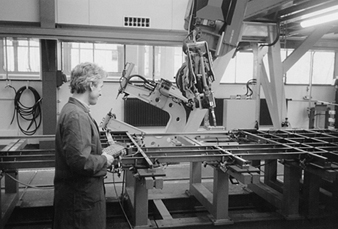
Accidents and Operating Modes
Fatal accidents involving industrial robots began to occur in the early 1980s. Statistics and investigations indicate that the majority of incidents and accidents do not take place in normal operation (automatic fulfilment of the assignment concerned). When working with industrial robot machines and installations, there is an emphasis on special operation modes such as commissioning, setting up, programming, test runs, checks, troubleshooting or maintenance. In these operating modes, persons are usually in a danger zone. The safety concept must protect personnel from negative events in these types of situations.
International Safety Requirements
The 1989 EEC Machinery Directive (89/392/EEC (see the article “Safety principles for CNC machine tools” in this chapter and elsewhere in this Encyclopaedia)) establishes the principal safety and health requirements for machines. A machine is considered to be the sum total of interlinked parts or devices, of which at least one part or device can move and correspondingly has a function. Where industrial robots are concerned, it must be noted that the entire system, not just one single piece of equipment on the machine, must meet the safety requirements and be fitted with the appropriate safety devices. Hazard analysis and risk assessment are suitable methods of determining whether these requirements have been satisfied (see figure 2).
Figure 2. Block diagram for a personnel security system
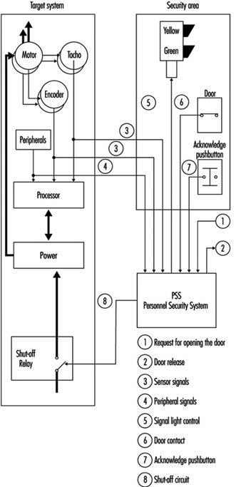
Requirements and Safety Measures in Normal Operation
The use of robot technology places maximum demands on hazard analysis, risk assessment and safety concepts. For this reason, the following examples and suggestions can serve only as guidelines:
1. Given the safety goal that manual or physical access to hazardous areas involving automatic movements must be prevented, suggested solutions include the following:
- Prevent manual or physical access into danger zones by means of mechanical barriers.
- Use safety devices of the sort which respond when approached (light barriers, safety mats), and take care to switch off machinery safely when accessed or entered.
- Permit manual or physical access only when the entire system is in a safe state. For example, this can be achieved by the use of interlocking devices with closure mechanisms on the access doors.
2. Given the safety goal that no person may be injured as a result of the release of energy (flying parts or beams of energy), suggested solutions include:
- Design should prevent any release of energy (e.g., correspondingly dimensioned connections, passive gripper interlocking devices for gripper change mechanisms, etc.).
- Prevent the release of energy from the danger zone, for example, by a correspondingly dimensioned safety hood.
3. The interfaces between normal operation and special operation (e.g., door interlocking devices, light barriers, safety mats) are necessary to enable the safety control system to automatically recognize the presence of personnel.
Demands and Safety Measures in Special Operation Modes
Certain special operation modes (e.g., setting up, programming) on an industrial robot require movements which must be assessed directly at the site of operation. The relevant safety goal is that no movements may endanger the persons involved. The movements should be
- only of the scheduled style and speed
- prolonged only as long as instructed
- those which may be performed only if it can be guaranteed that no parts of the human body are in the danger zone.
A suggested solution to this goal could involve the use of special operating control systems which permit only controllable and manageable movements using acknowledgeable controls. The speed of movements is thus safely reduced (energy reduction by the connection of an isolation transformer or the use of fail-safe state monitoring equipment) and the safe condition is acknowledged before the control is allowed to activate (see figure 3).
Figure 3. Six-axis industrial robot in a safety cage with material gates
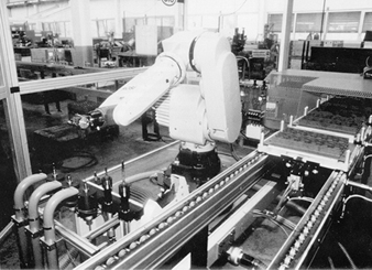
Demands on Safety Control Systems
One of the features of a safety control system must be that the required safety function is guaranteed to work whenever any faults arise. Industrial robot machines should be almost instantaneously directed from a hazardous state to a safe state. Safety control measures needed to achieve this include the following safety goals:
- A fault in the safety control system may not trigger off a hazardous state.
- A fault in the safety control system must be identified (immediately or at intervals).
Suggested solutions to providing reliable safety control systems would be:
- redundant and diverse layout of electro-mechanical control systems including test circuits
- redundant and diverse set-up of microprocessor control systems developed by different teams. This modern approach is considered to be state-of-the-art; for example, those complete with safety light barriers.
Safety Goals for the Construction and Use of Industrial Robots.
When industrial robots are built and used, both manufacturers as well as users are required to install state-of-the-art safety controls. Apart from the aspect of legal responsibility, there may also be a moral obligation to ensure that robot technology is also a safe technology.
Normal operation mode
The following safety conditions should be provided when robot machines are operating in the normal mode:
- The field of movement of the robot and the processing areas used by peripheral equipment must be secured in such a way as to prevent manual or physical access by persons to areas which are hazardous as a result of automatic movements.
- Protection should be provided so that flying workpieces or tools are not allowed to cause damage.
- No persons must be injured by parts, tools or workpieces ejected by the robot or by the release of energy, due to faulty gripper(s), gripper power failure, inadmissible speed, collision(s) or faulty workpiece(s).
- No persons may be injured by the release of energy or by parts ejected by peripheral equipment.
- Feed and removal apertures must be designed to prevent manual or physical access to areas which are hazardous as a result of automatic movements. This condition must also be fulfilled when production material is removed. If production material is fed to the robot automatically, no hazardous areas may be created by feed and removal apertures and the moving production material.
Special operation modes
The following safety conditions should be provided when robot machines are operating in special modes:
The following must be prevented during rectification of a breakdown in the production process:
- manual or physical access to areas which are hazardous due to automatic movements by the robot or by peripheral equipment
- hazards which arise from faulty behaviour on the part of the system or from inadmissible command input if persons or parts of the body are in the area exposed to hazardous movements
- hazardous movements or conditions initiated by the movement or removal of production material or waste products
- injuries caused by peripheral equipment
- movements that have to be carried out with the safety guard(s) for normal operation removed, to be carried out only within the operational scope and speed, and only as long as instructed. Additionally, no person(s) or parts of the body may be present in the area at risk.
The following safe conditions should be assured during set up:
No hazardous movements may be initiated as a result of a faulty command or incorrect command input.
- The replacement of robot machine or peripheral parts must not initiate any hazardous movements or conditions.
- If movements have to be carried out with the safety guard(s) for normal operation removed when conducting setting-up operations, such movements may be carried out only within the directed scope and speed and only as long as instructed. Additionally, no person(s) or parts of the body may be present in the area at risk.
- During setting-up operations, the peripheral equipment must not make any hazardous movements or initiate any hazardous conditions.
During programming, the following safety conditions are applicable:
- Manual or physical access to areas which are hazardous due to automatic movements must be prevented.
- If movements are carried out with the safety guard(s) for normal operation removed, the following conditions must be fulfilled:
- (a)Only the command to move may be carried out, and only for as long as it is issued.
- (b)Only controllable movements may be carried out (i.e., they must be clearly visible, low-speed movements).
- (c)Movements may be initiated only if they do not constitute a hazard to the programmer or other persons.
- Peripheral equipment must not represent a hazard to the programmer or other persons.
Safe test operations require the following precautions:
Prevent manual or physical access to areas which are hazardous due to automatic movements.
- Peripheral equipment must not be a source of danger.
When inspecting robot machines, safe procedures include the following:
- If it is necessary to enter the robot’s field of movement for inspection purposes, this is permissible only if the system is in a safe state.
- Hazards caused by faulty behaviour on the part of the system or by inadmissible command input must be prevented.
- Peripheral equipment must not be a source of danger to inspection personnel.
Troubleshooting often requires starting the robot machine while it is in a potentially hazardous condition, and special safe work procedures such as the following should be implemented:
- Access to areas which are hazardous as a result of automatic movements must be prevented.
- The starting up of a drive unit as a result of a faulty command or false command input must be prevented.
- In handling a defective part, all movements on the part of the robot must be prevented.
- Injuries caused by machine parts which are ejected or fall off must be prevented.
- If, during troubleshooting, movements have to be carried out with the safety guard(s) for normal operation removed, such movements may be carried out only within the scope and speed laid down and only as long as instructed. Additionally, no person(s) or parts of the body may be present in the area at risk.
- Injuries caused by peripheral equipment must be prevented.
Remedying a fault and maintenance work also may require start-up while the machine is in an unsafe condition, and therefore require the following precautions:
- The robot must not be able to start up.
- The handling of various machine parts, either manually or with ancillary equipment, must be possible without risk of exposure to hazards.
- It must not be possible to touch parts that are “live”.
- Injuries caused by the escape of liquid or gaseous media must be prevented.
- Injuries caused by peripheral equipment must be prevented.
Funeral Services
General Profile
Assuming a world population of 5 billion, between one-quarter and one-half of a million people die each day. Many of the dead are infants or children, but eventually everyone who is born will also die. Despite the diversity in culture and religious beliefs surrounding death, the bodily remains of each person must be disposed of. In general, the two main methods of disposing of human remains consist of burial and cremation. Both of these disposal methods often have been applied to the untreated human remains. Many cultures, however, have developed funeral rites that prescribe some treatment of the dead body. Simpler rites may include the washing of the external surface with herbs and spices to slow or mask the onset of decay and the smell associated with dead tissue. More sophisticated rites include intrusive procedures such as embalming and removal of internal organs. Embalming usually involves replacement of blood with an embalming or preserving fluid. The Egyptians were among the first culture to develop and practice embalming of the dead. Embalming has been extensively practiced in the twentieth century throughout Western Europe and North America. Embalming may be followed either by burial or cremation. Outside of Western Europe and North America, burial or cremation is usually not preceded by embalming.
Funeral Processes
The preparation and burial of a deceased person can involve many processes, including:
- washing the surface of the body with various preparations
- dressing the body in burial clothes
- autopsies, in certain circumstances, which involve intrusive procedure, such as dissection and analysis of blood and body tissues
- embalming and removal of internal organs
- application of cosmetics to cover up visible damage if the body is to be viewed
- transporting the body to place of burial or cremation
- lifting of body and casket, and lowering it into the grave
- digging and filling of the grave
- possible exhumation of the body and subsequent autopsy.
Three types of hazard are always associated with the handling of deceased humans: microbial, psychological and ergonomic. A fourth type of hazard - chemical exposure - is introduced when embalming is performed. In the United States many states have enacted laws that require a body to be embalmed if the deceased person will be viewed in a open casket.
Microbial Hazards
Death is often caused by disease. After death the germs that caused the disease may continue to live in the deceased person and can infect the people handling the dead body.
Contagious diseases such as the plague and smallpox have been spread by improper handling of victims who died from the diseases. The route of exposure must be considered when evaluating the microbial hazard associated with the handling of dead bodies. Many diseases are spread by touching a source of contamination and then introducing that disease-causing organism, or pathogen, to one’s mucous membranes by rubbing the eyes or nose, or by ingesting the pathogen. Some diseases can be contracted simply by inhaling the pathogen. Inhalation can be a special hazard during exhumation, when the remains are dry, or during procedures that aerosolize parts of the human body, such as sawing through the bone of a deceased person. The contagion of diseases is further exacerbated when procedures with sharp instruments are used in funeral rites. Such practices introduce the possibility of parenteral exposure.
Microbial hazards can be classified in many different ways, including the type of disease-causing organism, the type of disease, the severity of the disease and the route of infection. Perhaps the most useful way of discussing microbial hazards encountered by funeral workers is by route of infection. The routes of infection are ingestion, inhalation, touch or surface contact and parenteral, or puncture of a body surface.
Ingestion as a route of exposure can be controlled by proper personal hygiene - that is, always washing hands before eating or smoking, and by keeping food, drink or any object that will be put in the mouth (such as cigarettes) out of areas of possible contamination. This is important for controlling chemical exposure as well. In addition to careful personal hygiene, wearing impermeable gloves when handling the dead can reduce the probability of infection.
Inhalation exposure occurs only when disease-causing organisms become airborne. For funeral workers the two primary ways that pathogens can become airborne are during an exhumation or during autopsy procedures in which a saw is used to cut through bone. A third possibility of aerosolizing a pathogen - tuberculosis, for example - is when air is forced out of the lungs of a corpse during handling. Although the epidemics of the past have included plague, cholera, typhoid, tuberculosis, anthrax and smallpox, only the organisms causing anthrax and smallpox appear capable of surviving any length of time after burial (Healing, Hoffman and Young 1995). These pathogens would be found in any of the soft tissues, not the bones, and particularly in soft tissues that have become mummified and/or dried out and friable. The anthrax bacterium can form spores that remain viable for long periods, especially under dry conditions. Intact smallpox viruses taken from the tissues of bodies buried in the 1850s were identified under the electron microscope. None of the viruses grew in tissue culture and they were deemed to be non-infective (Baxter, Brazier and Young 1988). Smallpox virus has remained infective, however, after 13 years in dry storage under laboratory conditions (Wolff and Croon 1968). An article appearing in the Journal of Public Health (UK) during the 1850s reports concern about smallpox infectivity from remains buried two hundred years earlier in Montreal, when smallpox was widespread in the New World (Sly 1994).
Perhaps a more probable source of inhalation exposure during exhumation are fungal spores. Whenever old material of any sort is disturbed, protection against the inhalation of fungal spores should be provided. Disposable high efficiency particulate (HEPA) respirators, developed primarily for protection against tuberculosis and lead dust, are quite effective against fungal spores as well. In addition to microbial concerns, the possibility of exposure to wood dust and/or lead needs to be evaluated before any exhumation proceeds.
The primary route of infection for tuberculosis is inhalation. The incidence of tuberculosis has increased during the last quarter of the twentieth century, primarily due to decreased public health vigilance and the emergence of bacterial strains that are resistant to several groups of antibiotics. A recent study conducted at Johns Hopkins School of Public Health (Baltimore, Maryland, US) indicates that 18.8% of embalmers demonstrated positive results to tuberculin skin tests. Only 6.8% of people employed in the funeral business who are not embalmers demonstrated positive results to the same test. The lower rate of reactivity is similar to the general public (Gershon and Karkashion 1996).
Hepatitis B virus (HBV) and the human immunodeficiency virus (HIV) are infective if they come in contact with mucous membranes or are introduced into the bloodstream through a cut or puncture. A study of funeral service practitioners in Maryland indicated that 10% had a mucous membrane exposure within the past 6 months and 15% reported a needle stick within the past 6 months (Gershon et al. 1995). Other US studies reported that between 39 and 53% of morticians had a needle stick within the past 12 months (Nwanyanwu, Tubasuri and Harris 1989). In the United States, the reported prevalence of HBV is between 7.5 and 12.0% in unvaccinated funeral directors, and 2.6% or less in vaccinated funeral workers. The reported vaccination rate varies between 19 and 60% of morticians in the United States. Although there is a vaccine for HBV, there is currently no vaccine for HIV.
HIV and HBV are infective only when the virus comes into contact with the mucous membranes or is introduced into the bloodstream of another human. The virus is not absorbed through intact skin. Mucous membranes include the mouth, nose and eyes. These viruses can be introduced into the bloodstream through a cut or abrasion in the skin, or by puncturing or cutting the skin with an instrument that is contaminated with the virus. Hands that are cracked due to dryness or a hangnail may provide routes of entry for these viruses. Therefore, to prevent transmission of these diseases it is important to provide a barrier impermeable to body fluids, to avoid splashing contaminated fluids on the eyes, nose or mouth, and to prevent puncturing or cutting the skin with an instrument contaminated with HIV or HBV. Use of latex gloves and a face shield can often provide this protection. Latex gloves, however, have a limited shelf life depending on the amount of sunlight and heat to which they have been exposed. In general, the latex should be stress tested if the gloves have been stored for more than a year. Stress testing involves filling the glove with water and observing if any leaks develop during a minimum of two minutes. Some countries in the West, such as the United States and Great Britain, have adopted the idea of universal precautions, which means that every corpse is treated as if it were infected with HIV and HBV.
Psychological Hazards
In many cultures the family of the deceased prepares the body of their dead relative for burial or cremation. In other cultures a specialized group of individuals prepares the bodies of the dead for burial or cremation. There is a psychological effect on the living when they are involved in handling dead bodies. The psychological effect is real regardless of the procedures used in the funeral rites. Recently there has been an interest in identifying and evaluating the effects of performing funeral rites on those who actually perform them.
Although the psychological hazards of being a professional funeral worker have not been extensively studied, the psychological effects of dealing with the human remains of traumatic death have been recently analyzed. The main psychological effects appear to be anxiety, depression and somatization (the tendency to report physical ailments), as well as irritability, appetite and sleep disturbances, and increased alcohol use (Ursano et al. 1995). Post-traumatic stress disorder (PTSD) occurred in a significant number of individuals who handled the victims of traumatic deaths. Immediately after a disaster in which human remains were handled by rescue workers, between 20 and 40% of the rescue workers were considered to be in a high risk category, as demonstrated by psychological testing, but only about 10% of the rescue workers were diagnosed with PTSD. The psychological effects were still present in rescue workers one year after the disaster, but the incidence was greatly reduced. Adverse psychological effects, however, have been detected in individuals several years after the traumatic event.
Many of these studies were performed on military personnel. They indicate that generalized stress rates are higher in inexperienced individuals who were not volunteers, and that there was an increased incidence of stress indicators up to one year after a traumatic incident. Empathy or self-identification of the mortuary worker with the deceased appeared to be associated with an increased level of psychological stress (McCarroll et al. 1993; McCarroll et al. 1995).
One study evaluated the causes of death in 4,046 embalmers and funeral directors in the United States between 1975 and 1985, and reported a proportionate mortality ratio (PMR) of 130 for suicide. The PMR is a ratio of the actual number of suicides in the embalmers and funeral directors divided by the number of suicides that would be expected in a group of individuals comparable in age, race and sex who are not embalmers or funeral directors. This ratio is then multiplied by 100. The purpose of this study was to assess the risk of cancer in morticians, and the suicide statistic was not elaborated any further.
Ergonomics
A deceased human adult is heavy and usually must be carried to a designated place of burial or cremation. Even when mechanical means of transportation are used, the dead body must be transferred from the place of death to the vehicle and from the vehicle to the burial or cremation site. Out of respect for the dead person, this transfer is usually performed by other humans.
Morticians are required to move corpses many times during the course of body preparation and funerals. Although there were no studies found that addressed this issue, low-back pain and injury is associated with prolonged repetitive lifting of heavy objects. There are lifting devices available which can assist with these types of lifts.
Chemical Hazards
Embalming procedures introduce a number of potent chemicals into the workspace of funeral workers. Perhaps the most widely used and toxic of these is formaldehyde. Formaldehyde is irritating to the mucous membranes, the eyes, the nasal lining and the respiratory system, and has been associated with mutagenic cell changes and the development of cancer, as well as occupational asthma. During the past several decades the occupational exposure level associated with no adverse effects has been consistently lowered. Current 8-hour time-weighted average permissible exposure limits range from 0.5 ppm in Germany, Japan, Norway, Sweden and Switzerland to 5 ppm in Egypt and Taiwan (IARC 1995c). Formaldehyde levels between 0.15 and 4.3 ppm, with instantaneous levels as high as 6.6 ppm, have been reported for individual embalmings. An embalming typically takes between 1 and 2 hours. Additional formaldehyde exposure is associated with the application of embalming creams and drying and hardening powders, and during spills.
Rats that have been chronically exposed to 6 to 15 ppm of formaldehyde (Albert et al. 1982; Kerns et al. 1982; Tobe et al. 1985), or repeatedly exposed to 20 ppm for 15-minute periods (Feron et al. 1988), have developed nasal carcinomas (Hayes et al. 1990). The IARC reports limited epidemiological evidence for an association between formaldehyde exposure in industry and the development of human nasal and pharyngeal cancers (Olsen and Asnaes 1986; Hayes et al. 1986; Roush et al. 1987; Vaughan et al. 1986; Blair et al. 1986; Stayner et al. 1988). Several studies of morticians, however, have reported an increased incidence of leukaemias and brain tumours (Levine, Andjelkovich and Shaw 1984; Walrath and Fraumeni 1983). In addition to the carcinogenic effects, formaldehyde is irritating to the mucous membranes and has been considered a strong sensitizer in the development of adult-onset asthma. The mechanism or mechanisms by which formaldehyde precipitates asthma are even less well characterized than its role in the development of cancer.
Other potentially toxic chemicals used in embalming fluids include phenol, methanol, isopropyl alcohol and glutaraldehyde (Hayes et al. 1990). Glutaraldehyde appears to be even more irritating than formaldehyde to the mucous membranes, and affects the central nervous system at levels well above 500 ppm. Methanol also affects the central nervous system and, in particular, the vision system. Phenol appears to affect the nervous system as well as the lungs, heart, liver and kidneys, and is absorbed quite rapidly through the skin. Our understanding of the toxicology of, and our ability to perform risk assessment for, exposure to multiple chemicals simultaneously are not sufficiently sophisticated to analyse the physiological effects of the mixtures to which embalmers and funeral directors are exposed. Blair et al. (1990a) thought that the increased incidence of leukaemias and brain tumours reported in professional, but not industrial, workers was a result of exposure to chemicals other than formaldehyde.
Recent advances in the design of dissecting tables indicate that local downdrafting of vapours significantly reduces the exposure of individuals working in the vicinity (Coleman 1995). Wearing gloves while performing procedures that require skin contact with embalming fluids and creams also reduces the hazard. There has been some concern, however, that some of the latex gloves on the market may be permeable to formaldehyde. Therefore, protective gloves should be selected carefully. In addition to the immediate concerns about the hazards of formaldehyde exposure, evidence has been accumulating that leachate from cemeteries may lead to formaldehyde contamination of groundwater.
Exhumation of bodies may also involve chemical exposures. Although used sporadically for centuries, lead was commonly used to line coffins beginning in the eighteenth and continuing into the nineteenth century. Inhalation of wood dust is associated with respiratory problems, and fungus-contaminated wood dust is a double-edged sword. Arsenic and mercury compounds were also used as preservatives in the past and could present a hazard during exhumation.
Safety Principles for CNC Machine Tools
Whenever simple and conventional production equipment, such as machine tools, is automated, the result is complex technical systems as well as new hazards. This automation is achieved through the use of computer numeric control (CNC) systems on machine tools, called CNC machine tools (e.g., milling machines, machining centres, drills and grinders). In order to be able to identify the potential hazards inherent in automatic tools, the various operating modes of each system should be analysed. Previously conducted analyses indicate that a differentiation should be made between two types of operation: normal operation and special operation.
It is often impossible to prescribe the safety requirements for CNC machine tools in the shape of specific measures. This may be because there are too few regulations and standards specific to the equipment which provide concrete solutions. Safety requirements can be determined only if the possible hazards are identified systematically by conducting a hazard analysis, particularly if these complex technical systems are fitted with freely programmable control systems (as with CNC machine tools).
In the case of newly developed CNC machine tools, the manufacturer is obliged to carry out a hazard analysis on the equipment in order to identify whatever dangers may be present and to show by means of constructive solutions that all dangers to persons, in all of the different operating modes, are eliminated. All the hazards identified must be subjected to a risk assessment wherein each risk of an event is dependent on the scope of damage and the frequency with which it may occur. The hazard to be assessed is also given a risk category (minimized, normal, increased). Wherever the risk cannot be accepted on the basis of the risk assessment, solutions (safety measures) must be found. The purpose of these solutions is to reduce the frequency of occurrence and the scope of damage of an unplanned and potentially hazardous incident (an “event”).
The approaches to solutions for normal and increased risks are to be found in indirect and direct safety technology; for minimized risks, they are to be found in referral safety technology:
- Direct safety technology. Care is taken at the design stage to eliminate any hazards (e.g., the elimination of shearing and trapping points).
- Indirect safety technology. The hazard remains. However, the addition of technical arrangements prevents the hazard from turning into an event (e.g., such arrangements may include the prevention of access to dangerous moving parts by means of physical safety hoods, the provision of safety devices which turn power off, shielding from flying parts using safety guards, etc.).
- Referral safety technology. This applies only to residual hazards and minimized risks—that is, hazards which can lead to an event as a result of human factors. The occurrence of such an event can be prevented by appropriate behaviour on the part of the person concerned (e.g., instructions on behaviour in the operating and maintenance manuals, personnel training, etc.).
International Safety Requirements
The EC Machinery Directive (89/392/EEC) of 1989 lays down the principal safety and health requirements for machines. (According to the Machinery Directive, a machine is considered to be the sum total of interlinked parts or devices, of which at least one can move and correspondingly has a function.) In addition, individual standards are created by international standardization bodies to illustrate possible solutions (e.g., by attending to fundamental safety aspects, or by examining electrical equipment fitted to industrial machinery). The aim of these standards is to specify protection goals. These international safety requirements give manufacturers the necessary legal basis to specify these requirements in the above-mentioned hazard analyses and risk assessments.
Operating Modes
When using machine tools, a differentiation is made between normal operation and special operation. Statistics and investigations indicate that the majority of incidents and accidents do not take place in normal operation (i.e., during the automatic fulfilment of the assignment concerned). With these types of machines and installations, there is an emphasis on special modes of operations such as commissioning, setting up, programming, test runs, checks, troubleshooting or maintenance. In these operating modes, persons are usually in a danger zone. The safety concept must protect personnel from harmful events in these types of situations.
Normal operation
The following applies to automatic machines when carrying out normal operation: (1) the machine fulfils the assignment for which it was designed and constructed without any further intervention by the operator, and (2) applied to a simple turning machine, this means that a workpiece is turned to the correct shape and chips are produced. If the workpiece is changed manually, changing the workpiece is a special mode of operation.
Special modes of operation
Special modes of operation are working processes which allow normal operation. Under this heading, for example, one would include workpiece or tool changes, rectifying a fault in a production process, rectifying a machine fault, setting up, programming, test runs, cleaning and maintenance. In normal operation, automatic systems fulfil their assignments independently. From the viewpoint of working safety, however, automatic normal operation becomes critical when the operator has to intervene working processes. Under no circumstances may the persons intervening in such processes be exposed to hazards.
Personnel
Consideration must be given to the persons working in the various modes of operation as well as to third parties when safeguarding machine tools. Third parties also include those indirectly concerned with the machine, such as supervisors, inspectors, assistants for transporting material and dismantling work, visitors and others.
Demands and Safety Measures for Machine Accessories
Interventions for jobs in special operation modes mean that special accessories have to be used to assure work can be conducted safely. The first type of accessories include equipment and items used to intervene in the automatic process without the operator’s having to access a hazardous zone. This type of accessory includes (1) chip hooks and tongs which have been so designed that chips in the machining area can be removed or pulled away through the apertures provided in the safety guards, and (2) workpiece clamping devices with which the production material can be manually inserted into or removed from an automatic cycle
Various special modes of operation—for example, remedial work or maintenance work—make it necessary for personnel to intervene in a system. In these cases, too, there is a whole range of machine accessories designed to increase working safety—for example, devices to handle heavy grinding wheels when the latter are changed on grinders, as well as special crane slings for dismantling or erecting heavy components when machines are overhauled. These devices are the second type of machine accessory for increasing safety during work in special operations. Special operation control systems can also be considered to represent a second type of machine accessory. Particular activities can be carried out safely with such accessories—for example, a device can be set up in the machine axes when feed movements are necessary with the safety guards open.
These special operation control systems must satisfy particular safety requirements. For example, they must ensure that only the movement requested is carried out in the way requested and only for as long as requested. The special operation control system must therefore be designed in such a way as to prevent any faulty action from turning into hazardous movements or states.
Equipment which increases the degree of automation of an installation can be considered to be a third type of machine accessory for increasing working safety. Actions which were previously carried out manually are done automatically by the machine in normal operation, such as equipment including portal loaders, which change the workpieces on machine tools automatically. The safeguarding of automatic normal operation causes few problems because the intervention of an operator in the course of events is unnecessary and because possible interventions can be prevented by safety devices.
Requirements and Safety Measures for the Automation of Machine Tools
Unfortunately, automation has not led to the elimination of accidents in production plants. Investigations simply show a shift in the occurrence of accidents from normal to special operation, primarily due to the automation of normal operation so that interventions in the course of production are no longer necessary and personnel are thus no longer exposed to danger. On the other hand, highly automatic machines are complex systems which are difficult to assess when faults occur. Even the specialists employed to rectify faults are not always able to do so without incurring accidents. The amount of software needed to operate increasingly complex machines is growing in volume and complexity, with the result that an increasing number of electrical and commissioning engineers suffer accidents. There is no such thing as flawless software, and changes in software often lead to changes elsewhere which were neither expected nor wanted. In order to prevent safety from being affected, hazardous faulty behaviour caused by external influence and component failures must not be possible. This condition can be fulfilled only if the safety circuit is designed as simply as possible and is separate from the rest of the controls. The elements or sub-assemblies used in the safety circuit must also be fail-safe.
It is the task of the designer to develop designs that satisfy safety requirements. The designer cannot avoid having to consider the necessary working procedures, including the special modes of operation, with great care. Analyses must be made to determine which safe work procedures are necessary, and the operating personnel must become familiar with them. In the majority of cases, a control system for special operation will be necessary. The control system usually observes or regulates a movement, while at the same time, no other movement must be initiated (as no other movement is needed for this work, and thus none is expected by the operator). The control system does not necessarily have to carry out the same assignments in the various modes of special operation.
Requirements and Safety Measures in Normal and Special Modes of Operation
Normal operation
The specification of safety goals should not impede technical progress because adapted solutions can be selected. The use of CNC machine tools makes maximum demands on hazard analysis, risk assessment and safety concepts. The following describes several safety goals and possible solutions in greater detail.
Safety goal
- Manual or physical access to hazardous areas during automatic movements must be prevented.
Possible solutions
- Prevent manual or physical access into danger zones by means of mechanical barriers.
- Provide safety devices that respond when approached (light barriers, safety mats) and switch off machinery safely during interventions or entry.
- Allow manual or physical access to machinery (or its vicinity) only when the entire system is in a safe state (e.g., by using interlocking devices with closure mechanisms on the access doors).
Safety goal
- The possibility of any persons being injured as a result of the release of energy (flying parts or beams of energy) should be eliminated.
Possible solution
- Prevent the release of energy from the danger zone—for example, by a correspondingly dimensioned safety hood.
Special operation
The interfaces between normal operation and special operation (e.g., door interlocking devices, light barriers, safety mats) are necessary to enable the safety control system to recognize automatically the presence of personnel. The following describes certain special operation modes (e.g., setting up, programming) on CNC machine tools which require movements that must be assessed directly at the site of operation.
Safety goals
- Movements must take place only in such a way that they cannot be a hazard for the persons concerned. Such movements must be executed only in the scheduled style and speed and continued only as long as instructed.
- They are to be attempted only if it can be guaranteed that no parts of the human body are in the danger zone.
Possible solution
- Install special operating control systems which permit only controllable and manageable movements using finger-tip control via “acknowledge-type” push buttons. The speed of movements is thus safely reduced (provided that energy has been reduced by means of an isolation transformer or similar monitoring equipment).
Demands on Safety Control Systems
One of the features of a safety control system must be that the safety function is guaranteed to work whenever any faults arise so as to direct processes from a hazardous state to a safe state.
Safety goals
- A fault in the safety control system must not trigger off a dangerous state.
- A fault in the safety control system must be identified (immediately or at intervals).
Possible solutions
- Put in place a redundant and diverse layout of electro-mechanical control systems, including test circuits.
- Put in place a redundant and diverse set-up of microprocessor control systems developed by different teams. This approach is considered to be state of the art, for example, in the case of safety light barriers.
Conclusion
It is apparent that the increasing trend in accidents in normal and special modes of operation cannot be halted without a clear and unmistakable safety concept. This fact must be taken into account in the preparation of safety regulations and guidelines. New guidelines in the shape of safety goals are necessary in order to allow advanced solutions. This objective enables designers to choose the optimum solution for a specific case while at the same time demonstrating the safety features of their machines in a fairly simple way by describing a solution to each safety goal. This solution can then be compared with other existing and accepted solutions, and if it is better or at least of equal value, a new solution can then be chosen. In this way, progress is not hampered by narrowly formulated regulations.
Main Features of the EEC Machinery Directive
The Council Directive of 14 June 1989 on the approximation of the laws of the Member States relating machinery (89/392/EEC) applies to each individual state.
- Each individual state must integrate the directive in its legislation.
- Valid from 1 January 1993.
- Requires that all manufacturers adhere to the state of the art.
- The manufacturer must produce a technical construction file which contains full information on all fundamental aspects of safety and health care.
- The manufacturer must issue the declaration of conformity and the CE marking of the machines.
- Failure to place a complete technical documentation at the disposal of a state supervisory centre is considered to represent the non-fulfilment of the machine guidelines. A pan-EEC sales prohibition may be the consequence.
Safety Goals for the Construction and Use of CNC Machine Tools
1. Lathes
1.1 Normal mode of operation
1.1.1 The work area is to be safeguarded so that it is impossible to reach or step into the danger zones of automatic movements, either intentionally or unintentionally.
1.1.2 The tool magazine is to be safeguarded so that it is impossible to reach or step into the danger zones of automatic movements, either intentionally or unintentionally.
1.1.3 The workpiece magazine is to be safeguarded so that it is impossible to reach or step into the danger zones of automatic movements, either intentionally or unintentionally.
1.1.4 Chip removal must not result in personal injury due to the chips or moving parts of the machine.
1.1.5 Personal injuries resulting from reaching into drive systems must be prevented.
1.1.6 The possibility of reaching into the danger zones of moving chip conveyors must be prevented.
1.1.7 No personal injury to operators or third persons must result from flying workpieces or parts thereof.
For example, this can occur
- due to insufficient clamping
- due to inadmissible cutting force
- due to inadmissible rotation speed
- due to collision with the tool or machine parts
- due to workpiece breakage
- due to defective clamping fixtures
- due to power failure
1.1.8 No personal injury must result from flying workpiece clamping fixtures.
1.1.9 No personal injury must result from flying chips.
1.1.10 No personal injury must result from flying tools or parts thereof.
For example, this can occur
- due to material defects
- due to inadmissible cutting force
- due to a collision with the workpiece or a machine part
- due to inadequate clamping or tightening
1.2 Special modes of operation
1.2.1 Workpiece changing.
1.2.1.1 Workpiece clamping must be done in such a way that no parts of the body can become trapped between closing clamping fixtures and workpiece or between the advancing sleeve tip and workpiece.
1.2.1.2 The starting of a drive (spindles, axes, sleeves, turret heads or chip conveyors) as a consequence of a defective command or invalid command must be prevented.
1.2.1.3 It must be possible to manipulate the workpiece manually or with tools without danger.
1.2.2 Tool changing in tool holder or tool turret head.
1.2.2.1 Danger resulting from the defective behaviour of the system or due to entering an invalid command must be prevented.
1.2.3 Tool changing in the tool magazine.
1.2.3.1 Movements in the tool magazine resulting from a defective or invalid command must be prevented during tool changing.
1.2.3.2 It must not be possible to reach into other moving machine parts from the tool loading station.
1.2.3.3 It must not be possible to reach into danger zones on the further movement of the tool magazine or during the search. If taking place with the guards for normal operation mode removed, these movements may only be of the designated kind and only be carried out during the period of time ordered and only when it can be ensured that no parts of the body are in these danger zones.
1.2.4 Measurement check.
1.2.4.1 Reaching into the work area must only be possible after all movements have been brought to a standstill.
1.2.4.2 The starting of a drive resulting from a defective command or invalid command input must be prevented.
1.2.5 Set-up.
1.2.5.1 If movements are executed during set-up with the guards for normal mode of operation removed, then the operator must be safeguarded by another means.
1.2.5.2 No dangerous movements or changes of movements must be initiated as a result of a defective command or invalid command input.
1.2.6 Programming.
1.2.6.1 No movements may be initiated during programming which endanger a person in the work area.
1.2.7 Production fault.
1.2.7.1 The starting of a drive resulting from a defective command on invalid command input setpoint must be prevented.
1.2.7.2 No dangerous movements or situations are to be initiated by the movement or removal of the workpiece or waste.
1.2.7.3 Where movements have to take place with the guards for the normal mode of operation removed, these movements may only be of the kind designated and only executed for the period of time ordered and only when it can be ensured that no parts of the body are in these danger zones.
1.2.8 Troubleshooting.
1.2.8.1 Reaching into the danger zones of automatic movements must be prevented.
1.2.8.2 The starting of a drive as a result of a defective command or invalid command input must be prevented.
1.2.8.3 A movement of the machine on manipulation of the defective part must be prevented.
1.2.8.4 Personal injury resulting from a machine part splintering off or dropping must be prevented.
1.2.8.5 If, during troubleshooting, movements have to take place with the guards for the normal mode of operation removed, these movements may only be of the kind designated and only executed for the period of time ordered and only when it can be ensured that no parts of the body are in these danger zones.
1.2.9 Machine malfunction and repair.
1.2.9.1 The machine must be prevented from starting.
1.2.9.2 Manipulation of the different parts of the machine must be possible either manually or with tools without any danger.
1.2.9.3 It must not be possible to touch live parts of the machine.
1.2.9.4 Personal injury must not result from the issue of fluid or gaseous media.
2. Milling machines
2.1 Normal mode of operation
2.1.1 The work area is to be safeguarded so that it is impossible to reach or step into the danger zones of automatic movements, either intentionally or unintentionally.
2.1.2 Chip removal must not result in personal injury due to the chips or moving parts of the machine.
2.1.3 Personal injuries resulting from reaching into drive systems must be prevented.
No personal injury to operators or third persons must result from flying workpieces or parts thereof.
For example, this can occur
- due to insufficient clamping
- due to inadmissible cutting force
- due to collision with the tool or machine parts
- due to workpiece breakage
- due to defective clamping fixtures
- due to power failure
2.1.4 No personal injury must result from flying workpiece clamping fixtures.
2.1.5 No personal injury must result from flying chips.
2.1.6 No personal injury must result from flying tools or parts thereof.
For example, this can occur
- due to material defects
- due to inadmissible speed of rotation
- due to inadmissible cutting force
- due to collision with workpiece or machine part
- due to inadequate clamping or tightening
- due to power failure
Special modes of operation
2.2.1 Workpiece changing.
2.2.1.1 Where power-operated clamping fixtures are used, it must not be possible for parts of the body to become trapped between the closing parts of the clamping fixture and the workpiece.
2.2.1.2 The starting of a drive (spindle, axis) resulting from a defective command or invalid command input must be prevented.
2.2.1.3 The manipulation of the workpiece must be possible manually or with tools without any danger.
2.2.2 Tool changing.
2.2.2.1 The starting of a drive resulting from a defective command or invalid command input must be prevented.
2.2.2.2 It must not be possible for fingers to become trapped when putting in tools.
2.2.3 Measurement check.
2.2.3.1 Reaching into the work area must only be possible after all movements have been brought to a standstill.
2.2.3.2 The starting of a drive resulting from a defective command or invalid command input must be prevented.
2.2.4 Set-up.
2.2.4.1 If movements are executed during set-up with guards for normal mode of operation removed, the operator must be safeguarded by another means.
2.2.4.2 No dangerous movements or changes of movements must be initiated as a result of a defective command or invalid command input.
2.2.5 Programming.
2.2.5.1 No movements must be initiated during programming which endanger a person in the work area.
2.2.6 Production fault.
2.2.6.1 The starting of drive resulting from a defective command or invalid command input must be prevented.
2.2.6.2 No dangerous movements or situations must be initiated by the movement or removal of the workpiece or waste.
2.2.6.3 Where movements have to take place with the guards for the normal mode of operation removed, these movements may only be of the kind designated and only executed for the period of time ordered and only when it can be ensured that no parts of the body are in these danger zones.
2.2.7 Troubleshooting.
2.2.7.1 Reaching into the danger zones of automatic movements must be prevented.
2.2.7.2 The starting of a drive as a result of a defective command or invalid command input must be prevented.
2.2.7.3 Any movement of the machine on manipulation of the defective part must be prevented.
2.2.7.4 Personal injury resulting from a machine part splintering off or dropping must be prevented.
2.2.7.5 If, during troubleshooting, movements have to take place with the guards for the normal mode of operation removed, these movements may only be of the kind designated and only executed for the period of time ordered and only when it can be ensured that no parts of the body are in these danger zones.
2.2.8 Machine malfunction and repair.
2.2.8.1 Starting the machine must be prevented.
2.2.8.2 Manipulation of the different parts of the machine must be possible manually or with tools without any danger.
2.2.8.3 It must not be possible to touch live parts of the machine.
2.2.8.4 Personal injury must not result from the issue of fluid or gaseous media.
3. Machining centres
3.1 Normal mode of operation
3.1.1 The work area must be safeguarded so that is impossible to reach or step into the danger zones of automatic movements, either intentionally or unintentionally.
3.1.2 The tool magazine must be safeguarded so that it is impossible to reach or step into the danger zones of automatic movements.
3.1.3 The workpiece magazine must be safeguarded so that it is impossible to reach or step into the danger zones of automatic movements.
3.1.4 Chip removal must not result in personal injury due to the chips or moving parts of the machine.
3.1.5 Personal injuries resulting from reaching into drive systems must be prevented.
3.1.6 The possibility of reaching into danger zones of moving chip conveyors (screw conveyors, etc.) must be prevented.
3.1.7 No personal injury to operators or third persons must result from flying workpieces or parts thereof.
For example, this can occur
- due to insufficient clamping
- due to inadmissible cutting force
- due to collision with the tool or machine parts
- due to workpiece breakage
- due to defective clamping fixtures
- due to changing to the wrong workpiece
- due to power failure
3.1.8 No personal injury must result from flying workpiece clamping fixtures.
3.1.9 No personal injury must result from flying chips.
3.1.10 No personal injury must result from flying tools or parts thereof.
For example, this can occur
- due to material defects
- due to inadmissible speed of rotation
- due to inadmissible cutting force
- due to collision with workpiece or machine part
- due to inadequate clamping or tightening
- due to the tool flying out of the tool changer
- due to selecting the wrong tool
- due to power failure
3.2 Special modes of operation
3.2.1 Workpiece changing.
3.2.1.1 Where power-operated clamping fixtures are used, it must not be possible for parts of the body to become trapped between the closing parts of the clamping fixture and the workpiece.
3.2.1.2 The starting of a drive resulting from a defective command or invalid command input must be prevented.
3.2.1.3 It must be possible to manipulate the workpiece manually or with tools without any danger.
3.2.1.4 Where workpieces are changed in a clamping station, it must not be possible from this location to reach or step into automatic movement sequences of the machine or workpiece magazine. No movements must be initiated by the control while a person is present in the clamping zone. The automatic insertion of the clamped workpiece into the machine or workpiece magazine is only to take place when the clamping station is also safeguarded with a protective system corresponding to that for normal mode of operation.
3.2.2 Tool changing in the spindle.
3.2.2.1 The starting of a drive resulting from a defective command or invalid command input must be prevented.
3.2.2.2 It must not be possible for fingers to become trapped when putting in tools.
3.2.3 Tool changing in tool magazine.
3.2.3.1 Movements in the tool magazine resulting from defective commands or invalid command input must be prevented during tool changing.
3.2.3.2 It must not be possible to reach into other moving machine parts from the tool loading station.
3.2.3.3 It must not be possible to reach into danger zones on the further movement of the tool magazine or during the search. If taking place with the guards for the normal mode of operation removed, these movements may only be of the kind designated and only executed for the period of time ordered and only when it can be ensured that no parts of the body are in these danger zones.
3.2.4 Measurement check.
3.2.4.1 Reaching into the work area must only be possible after all movements have been brought to a standstill.
3.2.4.2 The starting of a drive resulting from a defective command or invalid command input must be prevented.
3.2.5 Set-up.
3.2.5.1 If movements are executed during set-up with the guards for normal mode of operation removed, then the operator must be safeguarded by another means.
3.2.5.2 No dangerous movements or changes of movement must be initiated as a result of a defective command or invalid command input.
3.2.6 Programming.
3.2.6.1 No movements must be initiated during programming which endanger a person in the work area.
3.2.7 Production fault.
3.2.7.1 The starting of a drive resulting from a defective command or invalid command input must be prevented.
3.2.7.2 No dangerous movements or situations must be initiated by the movement or removal of the workpiece or waste.
3.2.7.3 Where movements have to take place with the guards for the normal mode of operation removed, these movements may only be of the kind designated and only executed for the period of time ordered and only when it can be ensured that no parts of the body are in these danger zones.
3.2.8 Troubleshooting.
3.2.8.1 Reaching into the danger zones of automatic movements must be prevented.
3.2.8.2 The starting of a drive as a result of a defective command or invalid command input must be prevented.
3.2.8.3 Any movement of the machine on manipulation of the defective part must be prevented.
3.2.8.4 Personal injury resulting from a machine part splintering off or dropping must be prevented.
3.2.8.5 If, during troubleshooting, movements have to take place with the guards for the normal mode of operation removed, these movements may only be of the kind designated and only executed for the period of time ordered and only when it can be ensured that no parts of the body are in these danger zones.
3.2.9 Machine malfunction and repair.
3.2.9.1 Starting the machine must be prevented.
3.2.9.2 Manipulation of the different parts of the machine must be possible manually or with tools without any danger.
3.2.9.3 It must not be possible to touch live parts of the machine.
3.2.9.4 Personal injury must not result from the issue of fluid or gaseous media.
4. Grinding machines
4.1 Normal mode of operation
4.1.1 The work area is to be safeguarded so that it is impossible to reach or step into the danger zones of automatic movements, either intentionally or unintentionally.
4.1.2 Personal injuries resulting from reaching into drive systems must be prevented.
4.1.3 No personal injury to operators or third persons must result from flying workpieces or parts thereof.
For example, this can occur
- due to insufficient clamping
- due to inadmissible cutting force
- due to inadmissible rotation speed
- due to collision with the tool or machine parts
- due to workpiece breakage
- due to defective clamping fixtures
- due to power failure
4.1.4 No personal injury must result from flying workpiece clamping fixtures.
4.1.5 No personal injury or fires must result from sparking.
4.1.6 No personal injury must result from flying parts of grinding wheels.
For example, this can occur
- due to inadmissible rotation speed
- due to inadmissible cutting force
- due to material defects
- due to collision with workpiece or machine part
- due to inadequate clamping (flanges)
- due to using incorrect grinding wheel
Special modes of operation
4.2.1 Workpiece changing.
4.2.1.1 Where power-operated clamping fixtures are used, it must not be possible for parts of the body to become trapped between the closing parts of the clamping fixture and the workpiece.
4.2.1.2 The starting of a feed drive resulting from a defective command or invalid command input must be prevented.
4.2.1.3 Personal injury caused by the rotating grinding wheel must be prevented when manipulating the workpiece.
4.2.1.4 Personal injury resulting from a bursting grinding wheel must not be possible.
4.2.1.5 The manipulation of the workpiece must be possible manually or with tools without any danger.
4.2.2 Tool changing (grinding wheel changing)
4.2.2.1 The starting of a feed drive resulting from .a defective command or invalid command input must be prevented.
4.2.2.2 Personal injury caused by the rotating grinding wheel must not be possible during measuring procedures.
4.2.2.3 Personal injury resulting from a bursting grinding wheel must not be possible.
4.2.3 Measurement check.
4.2.3.1 The starting of a feed drive resulting from a defective command or invalid command input must be prevented.
4.2.3.2 Personal injury caused by the rotating grinding wheel must not be possible during measuring procedures.
4.2.3.3 Personal injury resulting from a bursting grinding wheel must not be possible.
4.2.4. Set-up.
4.2.4.1 If movements are executed during set-up with the guards for normal mode of operation removed, then the operator must be safeguarded by another means.
4.2.4.2 No dangerous movements or changes of movement must be initiated as a result of a defective command or invalid command input.
4.2.5 Programming.
4.2.5.1 No movements must be initiated during programming which endanger a person in the work area.
4.2.6 Production fault.
4.2.6.1 The starting of a feed drive resulting from a defective command or invalid command input must be prevented.
4.2.6.2 No dangerous movements or situations must be initiated by the movement or removal of the workpiece or waste.
4.2.6.3 Where movements have to take place with the guards for the normal mode of operation removed, these movements may only be of the kind designated and only executed for the period of time ordered and only when it can be ensured that no parts of the body are in these danger zones.
4.2.6.4 Personal injury caused by the rotating grinding wheel must be prevented.
4.2.6.5 Personal injury resulting from a bursting grinding wheel must not be possible.
4.2.7 Troubleshooting.
4.2.7.1 Reaching into the danger zones of automatic movements must be prevented.
4.2.7.2 The starting of a drive as a result of a defective command or invalid command input must be prevented.
4.2.7.3 Any movement of the machine on manipulation of the defective part must be prevented.
4.2.7.4 Personal injury resulting from a machine part splintering off or dropping must be prevented.
4.2.7.5 Personal injury caused the operator’s contacting or by the bursting of the rotating grinding wheel must be prevented.
4.2.7.6 If, during troubleshooting, movements have to take place with the guards for the normal mode of operation removed, these movements may only be of the kind designated and only executed for the period of time ordered and only when it can be ensured that no parts of the body are in these danger zones.
4.2.8 Machine malfunction and repair.
4.2.8.1 Starting the machine must be prevented.
4.2.8.2 Manipulation of the different parts of the machine must be possible manually or with tools without any danger.
4.2.8.3 It must not be possible to touch live parts of the machine.
4.2.8.4 Personal injury must not result from the issue of fluid or gaseous media.
More...
Laundries, Garment and Dry Cleaning
General Profile
Commercial laundries began as domestic enterprises, but have developed into businesses with many unique health and safety concerns. Laundries specializing in services for hospitals must deal with possible biological hazards, and those laundering work clothes for manufacturing or service workers may risk exposure to specific chemical hazards.
Dry cleaning reputedly originated in France in 1825 when a worker in a dye and cleaning factory spilled lamp oil on a soiled tablecloth (IARC 1995a). After the tablecloth dried, the spots had disappeared. Lamp oil is a hydrocarbon. Similar hydrocarbon solvents - turpentine, kerosene, benzene and gasoline - were used in the fledgling dry-cleaning industry. All these solvents had one major disadvantage: they were flammable, often resulting in fires and explosions (Wentz 1995). In 1928, W.J. Stoddard introduced a nearly odourless, petroleum-based solvent with a higher flashpoint, which reduced the risk of fire. Stoddard solvent gained widespread acceptance in the industry and is still used today.
At the turn of the century, advances in the synthesis of chlorinated hydrocarbons permitted development of nonflammable solvents for dry cleaning. Initially, carbon tetrachloride was preferred, but because of its toxicity and aggressiveness to metals, textiles and dyes, it was gradually replaced in the 1940s and 1950s by trichloroethylene and tetrachloroethylene (also commonly known as perchloroethylene, or PERC) (Wentz 1995). PERC (C2Cl4) is a colourless, clear, heavy liquid with an ethereal odour. Today, approximately 90% of US dry cleaners use PERC (EPA 1991a).
Although cleaning practices vary from country to country and from shop to shop, laundries and dry-cleaning shops are usually small businesses; about 70% of US dry-cleaning shops have fewer than four employees, who usually perform the cleaning at the same location as the shop. The employees of such a small business, many of whom typically labour more than eight hours per day, may be members of one family, sometimes including children. In many countries, the dry-cleaning family lives in the same building as the shop. An increasing trend among larger corporations is to operate multiple “drop” shops where customers leave soiled garments. The garments are transported to a central facility for cleaning, and later returned to the drop shops for customer pick-up. This arrangement confines hazardous waste to one site and reduces the solvent exposure of drop shop workers.
The Laundry and Dry-Cleaning Process
The dry-cleaning or laundry process usually begins when a customer brings soiled garments to a shop. Modern clothing is made from many different fibres and fabrics. Garments are inspected and sorted according to weight, colour, finish and fabric type prior to machine loading. Visible stains are treated at a spotting station with various chemicals, before or after cleaning, depending on the type of stain.
Cleaning is a three-step process: washing, extracting and drying (figure 1). Wet-process washing (laundering) uses detergent, water and possibly steam. In dry cleaning, detergent and water are added to the solvent to aid in soil removal. Clothes are manually loaded into the machine, and the cleaning solution is automatically injected. Machine contents are agitated for a period, then spun at high speed to extract the water or solvent and tumbled dry. Once garments have been removed from the dryer, they are pressed to remove wrinkles and restore their shape.
Figure 1. The dry cleaning process flow diagram.
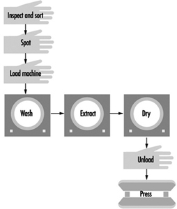
Many countries have recently imposed stringent regulations for the control of PERC exposures and emissions because of associated health effects and environmental problems. In response to these regulations, dry-cleaning processes are changing. Improved solvent purification and vapour-recovery systems are available, alternative solvents are being developed, and wet methods using water immersion are being refined to clean garments traditionally cleaned in solvent. These processes are described below.
Transfer versus dry-to-dry equipment
Two basic types of machines used in dry cleaning are transfer and dry-to-dry. Transfer machines, older and less expensive, require manual transfer of solvent-laden clothing from the washer to the dryer. The transfer activity causes excessive worker exposure to PERC. Because of high solvent usage rates, emissions and exposures during transfer, PERC transfer machines are no longer manufactured in the United States; however, older used or reconditioned ones can still be purchased.
In 1994, at least 70% of PERC machines in the United States, for example, were dry-to-dry machines, using a one-step process that eliminates clothing transfer. Many shops are replacing or have replaced transfer machines with dry-to-dry machines because of the trend towards stricter environmental regulations; however, some shops still use transfer equipment for increased productivity and to avoid the capital expenditure required for new machines. In the United States, petroleum machines are primarily transfer units.
Dry-to-dry machines may be vented or ventless. Vented dry-to-dry machines vent residual solvent vapours directly to the atmosphere or through some form of vapour-recovery system during the aeration process. Ventless dry-to-dry machines are essentially closed systems, open to the atmosphere only when the machine door is opened. They recirculate the heated drying air through a vapour-recovery system and back to the drying drum. There is no aeration step.
Solvent purification: Filtration and distillation
Dry cleaners use filtration and/or distillation to recover and purify solvents. Filtration removes insoluble soils, non-volatile residues and loose dyes from the solvent. It is also sometimes used, primarily in the United States, to remove soluble soils. Filtration is a continuous process. The solvent passes through an adsorbent powder, cartridge or spin-disc filter, all requiring some level of periodic maintenance. Each filtration system produces contaminated cartridges or powders.
Distillation, used by 90% of US cleaners, removes soluble oils, fatty acids and greases not removed by filtration (International Fabricare Institute 1990). Distillation occurs when PERC is heated to its boiling point so that it vaporizes and later condenses back to liquid form. During this process, non-volatile impurities, which cannot be boiled off, remain in the still and are discarded as hazardous waste. Both filtration and distillation produce some solid wastes containing PERC; however, dry-cleaning machine manufacturers are striving to develop new filtration and distillation technologies that reduce the amount of hazardous waste produced. This ultimately results in important savings to the owner by reducing the cost of hazardous-waste disposal.
Recovery of PERC vapours
Two primary technologies are used to recover PERC vapours: the carbon adsorber and the refrigerated condenser. These two technologies, traditionally separate, are used together in more modern machines. Carbon adsorption is used in about 35% of the controlled machines in the United States, for example. Carbon adsorbers achieve a 95 to 99% vapour reduction by removing PERC from the air. Solvent-laden vapours pass over activated carbon having a high adsorption capacity. The carbon is later desorbed and the PERC recovered, or the carbon is discarded as hazardous waste when it becomes saturated with PERC. Carbon desorption typically occurs with steam or hot air. Desorption can be done automatically after each load, or it can be done at the end of the day. If not performed regularly, the carbon bed will become saturated and be ineffective for PERC recovery. The adsorption system can handle high volumes of air, having relatively low solvent concentrations while maintaining a high PERC removal efficiency, but frequent desorbing is needed and steam regeneration produces contaminated waste water.
Refrigerated condensers cool solvent-laden air below the dew point of the vapour to recover PERC, and operate on the principle that the ability of air to hold a solvent in the vapour state varies with temperature. Refrigerated condensers are used in approximately 65% of controlled machines. The process can achieve 95% vapour control in dry-to-dry machines and 85% control in transfer machines. Condensers require little maintenance and minimize the potential for waste water because steam regeneration is not required. They do require higher solvent concentrations than a carbon adsorber. Water vapour may pose a problem because it can condense and freeze, impeding gas flow and heat transfer (EPA 1991b).
Solvent alternatives to PERC
Alternative dry-cleaning solvents have been substituted for PERC. Flammable, petroleum-based solvents generally have higher exposure limits than PERC. These petroleum-based solvents are less aggressive at removing soils than PERC. Because their vapour pressures are lower than PERC, exposures from inhalation will generally be lower. However, adverse health effects are possible, including asphyxiation, central nervous system depression and skin and mucous membrane irritation. Contamination of aliphatic hydrocarbons with benzene will significantly increase the hazard.
Two different approaches have been taken in Germany to reduce the fire hazard posed by petroleum-based solvents: developing safer solvents and redesigning machines.
Recently developed petroleum-based solvents, widely used in Germany, are either straight-chain, branched or cyclic paraffins with a chain length of between 10 and 12 carbons. These petroleum-based solvents have an atmospheric lifetime of only a few days, are halogen-free, do not lead to ozone depletion and play only a minor role in the greenhouse effect. Some of the German requirements for petroleum-based, dry-cleaning solvents are outlined below (Hohenstein Institute 1995):
- Boiling range between 180° and 210ºC
- Aromatic, benzene, halogen and polycyclic aromatic content less than 0.01 wt%
- Flashpoint higher than 55ºC
- Thermally stable at operating conditions.
Dry-cleaning machines manufactured for petroleum-based solvents in Germany today are much safer than those of the past. Because petroleum-based solvents are combustible, additional safety measures are required on machines using them. Technical advances improve machine safety and greatly reduce the risk of fire/explosion. The following measures can be taken in combination or separately:
- Using an inert gas, such as nitrogen or argon, to displace oxygen in the drum and ensure that oxygen concentration is sufficiently low (approximately 4%) to prevent combustion
- Operating under a vacuum to remove oxygen and lower its concentration to below 4%
- Ensuring that the lower explosive limit (LEL) is not exceeded, or if the LEL is not known, ensuring that operating temperature remains 15ºC below the flashpoint
- Ensuring that vapour concentration remains below 50º of the LEL, by controlling operating temperatures or by providing sufficiently high airflow.
Wet cleaning
Wet cleaning is a developing technology, distinct from traditional laundering in that it is a more gentle process and can be used on many fabrics that were formerly dry cleaned. Four factors play an essential role in soil removal: temperature, time, mechanical action and chemical agents. Only the proper blend of these factors achieves the best cleaning results (Vasquez 1995). There are minor variations of machine wet cleaning, but all techniques use:
- Specially formulated wet-cleaning soaps and spotting agents
- Increased extraction of water prior to drying (extraction speeds as high as approximately 1,000 revolutions per minute)
- Close monitoring of heat and moisture content during the drying process
- Machines having less mechanical action during washing, accomplished by speed reduction and time limits.
Garments are washed with various levels of limited mechanical action, based on garment type and amount of soilage. The greatest risk occurs during drying. Many fibres can be fully dried with little or no difficulty. However, delicate garments or garments susceptible to shrinkage must be dried for only a few minutes before being hung to air dry. Because of these problems, most wet-cleaned garments require more finishing work than solvent-cleaned garments. Long drying times and more finishing work substantially increase processing time (Earnest and Spencer 1996).
Today, wet cleaning use is limited because the technology does not yet completely eliminate the need for solvents. It has been estimated that wet cleaning can safely clean approximately 30 to 70% of garments traditionally cleaned in solvent (Rice and Weinberg 1994). There are still problems with fibre damage, bleeding of dyes and, most importantly, cleaning ability. Inappropriate use of wet cleaning can expose shop owners to liability for damaged clothing. For this reason wet-cleaning advocates are working to persuade garment manufacturers to use fabrics that can be more easily wet cleaned.
Hazards in Laundries and Dry Cleaning Facilities
PERC hazards
In the workplace PERC can enter the human body through both respiratory and dermal exposure (ATSDR 1995). Symptoms associated with respiratory exposure include depression of the central nervous system; damage to the liver and kidneys (RSC 1986); impaired memory; confusion; dizziness; headache; drowsiness; and eye, nose and throat irritation. Repeated dermal exposure may result in dry, scaly and fissured dermatitis (NIOSH 1977).
US National Cancer Institute and National Toxicology Program studies have established a link between PERC exposure and cancer in animals. Human studies show an elevated risk of urinary tract (Duh and Asal 1984; Blair et al. 1990b; Katz and Jowett 1981), oesophageal (Duh and Asal 1984; Ruder, Ward and Brown 1994) and pancreatic cancer (Lin and Kessler 1981) among dry-cleaning workers. The International Agency for Research on Cancer (IARC) recently classified PERC in group 2A (probably carcinogenic to humans) and dry cleaning in group 2B (possibly carcinogenic to humans) (IARC 1995b). The Environmental Protection Agency (EPA) regulates PERC as a hazardous air pollutant.
US Occupational Safety and Health Administration (OSHA) data include numerous personal samples in dry-cleaning shops over the permissible exposure limit (PEL) of 100 ppm, 8-hour time-weighted average (TWA) (OSHA 1993). The machine operator is typically exposed to the greatest concentrations of PERC. US National Institute for Occupational Safety and Health (NIOSH) studies have shown that in many dry-cleaning shops having traditional machines, extremely high operator exposures occur during loading and unloading. Because loading/unloading occurs frequently throughout the day, in many instances exposure during this activity can account for 50 to 75% of the operator’s TWA exposure (Earnest 1996). Occupational exposures can be reduced by using modern dry-cleaning machines, solvent substitution, isolation of the process and effective local and general ventilation near the dry-cleaning machines.
Exposure to chemicals other than PERC
A wide variety of chemicals is present in laundries and dry-cleaning establishments. There is potential exposure through skin or eye contact or inhalation of vapours. Skin damage may occur from chronic or acute exposure. Chemicals that readily vaporize and have a high toxicity may pose a risk from inhalation, although this is generally considered to be of less concern than injury to the eyes or skin. The chemicals commonly used in the United States to treat stains through spotting are trichloroethylene; ketones, especially methyl isobutyl ketone (MIBK); petroleum naphtha; and hydrofluoric acid. Oxidizers, such as chlorine bleaches, may pose a hazard if used in the presence of many common compounds, such as turpentine, ammonia or fuel gases. Detergents containing enzymes may cause immune reactions in many workers. The combined exposures of the dry-cleaning solvent, PERC and various other chemicals is also a concern.
Ergonomic risk factors
Ergonomic hazards in the cleaning industry primarily occur among pressers. Pressing is a dynamic and repetitive task requiring reaching, precision gripping and awkward postures. Ergonomic risk factors are also present during material handling when heavy lifting may occur, especially in commercial laundries.
Fire hazards
The dry-cleaning industry has traditionally had a problem with fires. Part of the reason for this problem has been the widespread use of flammable and combustible liquids as a cleaning medium. The flammability of petroleum-based solvents continues to present an acute health and safety hazard. Approximately 10% of dry-cleaning shops in the United States use traditional, petroleum-based solvents, such as Stoddard solvent or mineral spirits. Even dry-cleaning shops that use non-flammable PERC face important fire hazards. If heated sufficiently, PERC will decompose into hydrogen chloride and phosgene gases. The production of hydrogen cyanide or carbon monoxide is another cause for concern during a fire. Hydrogen cyanide is produced when materials that contain nitrogen, such as many natural and synthetic fibres burn. Carbon monoxide is formed during incomplete combustion. All dry-cleaning shops have a large number of potential fuels and ignition sources.
Dry-cleaning machine designers must avoid conditions that can lead to a fire to occur and must ensure that their machines operate safely. Likewise, shop owners must take appropriate steps to prevent hazardous conditions from developing. Some common causes of fires in all businesses are electrical malfunctions, friction, open flames, sparks, static electricity, hot surfaces and smoking (NIOSH 1975).
Thermal burns
Cleaning facilities have several possible sources of severe burns. In the pressing station, burns may result from contact with the head of a press, lines transporting steam, or the steam itself. Insulation of pipes and surfaces, and use of various guarding techniques, can help prevent burns.
Although modern boilers are of safer design than earlier models, they are still used to produce large quantities of steam and must be operated safely. Many of the needed precautions can be found in the US National Fire Protection Association’s Code 32, Standard for Dry Cleaning Plants, and its Fire Protection Handbook (NFPA 1991). Recommendations in these documents include building code requirements, proper storage and isolation of flammables, fire extinguishers and sprinkler systems. Recommendations concerning the build-up of gases around the boiler address ways to eliminate gas leakage and ensure proper ventilation.
Mechanical hazards
Mechanical hazards are always a concern when powered equipment is used. Presses pose a significant mechanical hazard. Presses designed to be activated by only one hand leave a potential for the worker’s free hand to be caught between the presses. Belts, drive chains, shafts and couplings should be guarded to prevent accidental contact. All moving components of machines should be guarded to prevent body parts from becoming caught in a pinch, nip or shear point. The most common methods of guarding a hazard are enclosing the operation, interlocking devices, moving barriers, removal devices, remote controls, two-hand tripping devices and electronic safety devices.
Electrical hazards
Numerous measures can be taken to limit electrical hazards. Especially important is proper insulation and grounding. Identification and guarding of live parts also helps to prevent injury from electrical current. Electrical hazards can be compounded by the presence of moisture. Ground-fault circuit interrupters are designed to shut off power if high current passes through an unintended path. When selecting electrical equipment, the recommendations of established codes and standards, such as the US National Fire Protection Association 70, the National Electrical Code and the American National Standards Institute’s C2, should be followed. Guidelines for appropriate use of electrical equipment are given elsewhere in this Encyclopaedia.
Heat stress
Heat stress can afflict workers who must labour for extended periods of time in the hot environments that exist in many cleaning facilities. Heat stress may be compounded in the summer months, particularly if the shop is not air conditioned (air conditioning is not common in this industry). Both physical and environmental factors will modify the effects of heat. Acclimatization, body surface area to weight ratio, age and diseases, water and salt balance and physical fitness all play a role in the likelihood an individual will be affected by heat stress.
Slips, trips and falls
The hazard of slips, trips and falls are especially pertinent to cleaning facilities, which are often crowded with people and equipment. Without clearly established aisles and with a large number of containers holding solvents or water, spills can easily occur, resulting in a slippery floor. To control this hazard, regular housekeeping must be emphasized, facility layout must be carefully planned, and floor surfaces should be of non-slip materials. The workplace should be maintained in a clean, orderly, sanitary condition, and any spills should be cleaned up promptly.
Biological hazards
Laundering hospital linens puts sorters at risk from overlooked sharp objects in sheets or uniform pockets. Both dry cleaners and launderers may encounter freshly soiled garments that have been contaminated with human body fluids. Garments that have come from dental and medical offices or labs, blood banks, drug treatment centers, clinics, mortuaries, ambulances and other health-care facilities can be reasonably suspected to contain potentially infectious materials. In many countries, shops that handle garments from these sources must comply with the occupational standards governing exposures, such as the OSHA regulations governing bloodborne pathogens.
Environmental and Public Health Concerns
Environmental and public health concerns have resulted in dramatic changes in environmental regulations affecting the dry-cleaning industry in recent years. Adjacent apartments and businesses can be exposed to PERC vapours by diffusion through walls or ceilings; indoor airflow through holes in ceilings, pipe chases or vents; and through PERC emissions vented outside of the shop that are re-entrained through opened windows or ventilation units. Groundwater or soil contamination can occur through frequent or large solvent spills that might occur during transfer of solvent from a delivery truck to the dry-cleaning machine. Soil contamination might also occur through improper disposal of separator water into the sanitary sewer. Finally, consumers may be exposed from PERC residuals in poorly dried garments. This is of particular concern if the cleaning machine is not functioning properly or the dry cycle is shortened to improve productivity.
Acknowledgement: This article is largely based on materials assembled and published by the US National Institute for Occupational Safety and Health (NIOSH).
Principles for the Design of Safe Control Systems
It is generally agreed that control systems must be safe during use. With this in mind, most modern control systems are designed as shown in figure 1.
Figure 1. General design of control systems
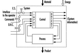
The simplest way to make a control system safe is to construct an impenetrable wall around it so as to prevent human access or interference into the danger zone. Such a system would be very safe, albeit impractical, since it would be impossible to gain access in order to perform most testing, repair and adjustment work. Because access to danger zones must be permitted under certain conditions, protective measures other than just walls, fences and the like are required to facilitate production, installation, servicing and maintenance.
Some of these protective measures can be partly or fully integrated into control systems, as follows:
- Movement can be stopped immediately should anybody enter the danger zone, by means of emergency stop (ES) buttons.
- Push-button controls permit movement only when the push-button is activated.
- Double-hand controls (DHC) permit movement only when both hands are engaged in depressing the two control elements (thus ensuring that hands are kept away from the danger zones).
These types of protective measures are activated by operators. However, because human beings often represent a weak point in applications, many functions, such as the following, are performed automatically:
- Movements of robot arms during the servicing or “teach-in” are very slow. Nonetheless, speed is continuously monitored. If, because of a control system failure, the speed of automatic robot arms were to increase unexpectedly during either the servicing or teach-in period, the monitoring system would activate and immediately terminate movement.
- A light barrier is provided to prevent access into a danger zone. If the light beam is interrupted, the machine will stop automatically.
Normal function of control systems is the most important precondition for production. If a production function is interrupted due to a control failure, it is at most inconvenient but not hazardous. If a safety-relevant function is not performed, it could result in lost production, equipment damage, injury or even death. Therefore, safety-relevant control system functions must be more reliable and safer than normal control system functions. According to European Council Directive 89/392/EEC (Machine Guidelines), control systems must be designed and constructed so that they are safe and reliable.
Controls consist of a number of components connected together so as to perform one or more functions. Controls are subdivided into channels. A channel is the part of a control that performs a specific function (e.g., start, stop, emergency stop). Physically, the channel is created by a string of components (transistors, diodes, relays, gates, etc.) through which, from one component to the next, (mostly electrical) information representing that function is transferred from input to output.
In designing control channels for safety-relevant functions (those functions which involve humans), the following requirements must be fulfilled:
- Components used in control channels with safety-relevant functions must be able to withstand the rigours of normal use. Generally, they must be sufficiently reliable.
- Errors in the logic must not cause dangerous situations. Generally, the safety-relevant channel is to be sufficiently failure proof.
- External influences (factors) should not lead to temporary or permanent failures in safety-relevant channels.
Reliability
Reliability is the ability of a control channel or component to perform a required function under specified conditions for a given period of time without failing. (Probability for specific components or control channels can be calculated using suitable methods.) Reliability must always be specified for a specific time value. Generally, reliability can be expressed by the formula in figure 2.
Figure 2. Reliability formula
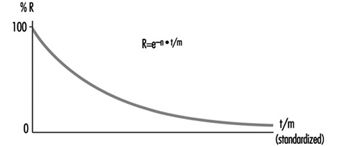
Reliability of complex systems
Systems are built from components. If the reliabilities of the components are known, the reliability of the system as a whole can be calculated. In such cases, the following apply:
Serial systems
The total reliability Rtot of a serial system consisting of N components of the same reliability RC is calculated as in figure 3.
Figure 3. Reliability graph of serially connected components
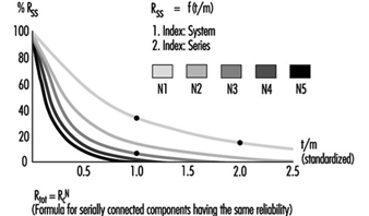
The total reliability is lower than the reliability of the least reliable component. As the number of serially connected components increases, the total reliability of the chain falls significantly.
Parallel systems
The total reliability Rtot of a parallel system consisting of N components of the same reliability RC is calculated as in figure 4.
Figure 4. Reliability graph of parallel connected components
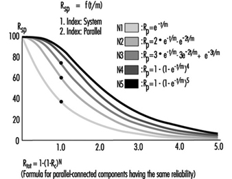
Total reliability can be improved significantly through the parallel connection of two or more components.
Figure 5 illustrates a practical example. Note that the circuitry will switch off the motor more reliably. Even if relay A or B fails to open its contact, the motor will still be switched off.
Figure 5. Practical example of figure 4
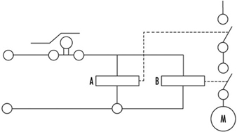
To calculate the total reliability of a channel is simple if all necessary component reliabilities are known and available. In the case of complex components (integrated circuits, microprocessors, etc.) the calculation of the total reliability is difficult or impossible if the necessary information is not published by the manufacturer.
Safety
When professionals speak about safety and call for safe machines, they mean the safety of the entire machine or system. This safety is, however, too general, and not precisely enough defined for the designer of controls. The following definition of safety may be practical and usable to designers of control circuitry: Safety is the ability of a control system to perform the required function within prescribed limits, for a given duration, even when anticipated fault(s) occur. Consequently, it must be clarified during the design how “safe” the safety-related channel must be. (The designer can develop a channel that is safe against first failure, against any one failure, against two failures, etc.) Furthermore, a channel that performs a function which is used to prevent accidents may be essentially reliable, but it does not have to be inevitably safe against failures. This may be best explained by the following examples:
Example 1
The example illustrated in figure 6 is a safety-relevant control channel performing the required safety function. The first component may be a switch that monitors, for example, the position of an access door to a dangerous area. The last component is a motor which drives moving mechanical parts within the danger area.
Figure 6. A safety-relevant control channel performing the required safety function
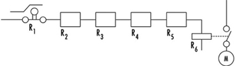
The required safety function in this case is a dual one: If the door is closed, the motor may run. If the door is open, the motor must be switched off. Knowing reliabilities R1 to R6, it is possible to calculate reliability Rtot. Designers should use reliable components in order to maintain sufficiently high reliability of the whole control system (i.e., the probability that this function may still be performed in, say, even 20 years should be accounted for in the design). As a result, designers must fulfil two tasks: (1) the circuitry must perform the required function, and (2) the reliability of the components and of the whole control channel must be adequate.
The following question should now be asked: Will the aforementioned channel perform the required safety functions even if a failure occurs in the system (e.g., if a relay contact sticks or a component malfunctions)? The answer is “No”. The reason is that a single control channel consisting only of serially connected components and working with static signals is not safe against one failure. The channel can have only a certain reliability, which guarantees the probability that the function will be carried out. In such situations, safety is always meant as failure related.
Example 2
If a control channel is to be both reliable and safe, the design must be modified as in figure 7. The example illustrated is a safety-relevant control channel consisting of two fully separated subchannels.
Figure 7. A safety-relevant control channel with two fully separate subchannels
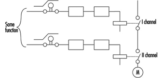
This design is safe against the first failure (and possible further failures in the same subchannel), but is not safe against two failures which may occur in two different subchannels (simultaneously or at different times) because there is no failure detection circuit. Consequently, initially both subchannels work with a high reliability (see parallel system), but after the first failure only one subchannel will work, and reliability decreases. Should a second failure occur in the subchannel still working, both will have then failed, and the safety function will no longer be performed.
Example 3
The example illustrated in figure 8 is a safety-relevant control channel consisting of two fully separate subchannels which monitor each other.
Figure 8. A safety-relevant control channel with two fully separate subchannels which monitor each other
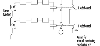
Such a design is failure safe because after any failure, only one subchannel will be non-functional, while the other subchannel remains available and will perform the safety function. Moreover, the design has a failure detection circuit. If, due to a failure, both subchannels fail to work in the same way, this condition will be detected by “exclusive or” circuitry, with the result that the machine will be automatically switched off. This is one of the best ways of designing machine controls—designing safety-relevant subchannels. They are safe against one failure and at the same time provide enough reliability so that the chances that two failures will occur simultaneously is minuscule.
Redundancy
It is apparent that there are various methods by which a designer may improve reliability and/or safety (against failure). The previous examples illustrate how a function (i.e., door closed, motor may run; door opened, motor must be stopped) can be realized by various solutions. Some methods are very simple (one subchannel) and others more complicated (two subchannels with mutual supervising). (See figure 9.)
Figure 9. Reliability of redundant systems with or without failure detection
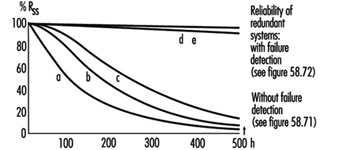
There is a certain redundancy in the complex circuitry and/or components in comparison with the simple ones. Redundancy can be defined as follows: (1) Redundancy is the presence of more means (components, channels, higher safety factors, additional tests and so on) than are really necessary for the simple fulfilling of the desired function; (2) redundancy obviously does not “improve” the function, which is performed anyway. Redundancy only improves reliability and/or safety.
Some safety professionals believe that redundancy is only the doubling or tripling, and so on, of the system. This is a very limited interpretation, as redundancy may be interpreted much more broadly and flexibly. Redundancy may be not only included in the hardware; it may be included in the software too. Improving the safety factor (e.g., a stronger rope instead of a weaker rope) may also be considered as a form of redundancy.
Entropy
Entropy, a term found mostly in thermodynamics and astronomy, may be defined as follows: Everything tends towards decay. Therefore, it is absolutely certain that all components, subsystems or systems, independently of the technology in use, will fail sometime. This means that there are no 100% reliable and/or safe systems, subsystems or components. All of them are merely more or less reliable and safe, depending on the structure’s complexity. The failures which inevitably occur earlier or later demonstrate the action of entropy.
The only means available to designers to counter entropy is redundancy, which is achieved by (a) introducing more reliability into the components and (b) providing more safety throughout the circuit architecture. Only by sufficiently raising the probability that the required function will be performed for the required period of time, can designers in some degree defend against entropy.
Risk Assessment
The greater the potential risk, the higher the reliability and/or safety (against failures) that is required (and vice versa). This is illustrated by the following two cases:
Case 1
Access to the mould tool fixed in an injection moulding machine is safeguarded by a door. If the door is closed, the machine may work, and if the door is opened, all dangerous movements have to be stopped. Under no circumstances (even in case of failure in the safety-related channel) may any movements, especially those which operate the tool, occur.
Case 2
Access to an automatically controlled assembly line that assembles small plastic components under pneumatic pressure is guarded by a door. If this door is opened, the line will have to be stopped.
In Case 1, if the door-supervising control system should fail, a serious injury may occur if the tool is closed unexpectedly. In Case 2, only slight injury or insignificant harm may result if the door-supervising control system fails.
It is obvious that in the first case much more redundancy must be introduced to attain the reliability and/or safety (against failure) required to protect against extreme high risk. In fact, according to European Standard EN 201, the supervising control system of the injection moulding machine door has to have three channels; two of which are electrical and mutually supervised and one of which is mostly equipped with hydraulics and testing circuits. All these three supervising functions relate to the same door.
Conversely, in applications like that described in Case 2, a single channel activated by a switch with positive action is appropriate to the risk.
Control Categories
Because all of the above considerations are generally based on information theory and consequently are valid for all technologies, it does not matter whether the control system is based on electronic, electro-mechanical, mechanical, hydraulic or pneumatic components (or a mixture of them), or on some other technology. The inventiveness of the designer on the one hand and economic questions on the other hand are the primary factors affecting a nearly endless number of solutions as to how to realize safety-relevant channels.
To prevent confusion, it is practical to set certain sorting criteria. The most typical channel structures used in machine controls for performing safety-related functions are categorized according to:
- reliability
- behaviour in case of failure
- failure-disclosing time.
Their combinations (not all possible combinations are shown) are illustrated in table 1.
Table 1. Some possible combinations of circuit structures in machine controls for safety-related functions
|
Criteria (Questions) |
Basic strategy |
|||||
|
By raising the reliability (is the occurrence of failure shifted to the possibly far future?) |
By suitable circuit structure (architecture) failure will be at least detected (Cat. 2) or failure effect on the channel will be eliminated (Cat. 3) or failure will be disclosed immediately (Cat. 4) |
|||||
|
Categories |
||||||
|
This solution is basically wrong |
B |
1 |
2 |
3 |
4 |
|
|
Can the circuit components with stand the expected influences; are they constructed according to state of the art? |
No |
Yes |
Yes |
Yes |
Yes |
Yes |
|
Have well tried components and/or methods been used? |
No |
No |
Yes |
Yes |
Yes |
Yes |
|
Can a failure be detected automatically? |
No |
No |
No |
Yes |
Yes |
Yes |
|
Does a failure prevent the performing of the safety-related function? |
Yes |
Yes |
Yes |
Yes |
No |
No |
|
When will the failure be detected? |
Never |
Never |
Never |
Early (latest at the end of interval that is not longer than one machine cycle) |
Immediately (when the signal loses dynamical |
|
|
In consumer products |
To be used in machines |
|||||
The category applicable for a specific machine and its safety-related control system is mostly specified in the new European standards (EN), unless the national authority, the user and the manufacturer mutually agree that another category should be applied. The designer then develops a control system which fulfils the requirements. For example, considerations governing the design of a control channel may include the following:
- The components have to withstand the expected influences. (YES/NO)
- Their construction should be according to state-of-the-art standards. (YES/NO)
- Well-tried components and methods are used. (YES/NO)
- Failure must be detected. (YES/NO)
- Will the safety function be performed even in case of failure? (YES/NO)
- When will the failure be detected? (NEVER, EARLY, IMMEDIATELY)
This process is reversible. Using the same questions, one can decided which category an existing, previously developed control channel belongs to.
Category examples
Category B
The control channel components primarily used in consumer wares have to withstand the expected influences and be designed according to state of the art. A well-designed switch may serve as an example.
Category 1
The use of well-tried components and methods is typical for Category 1. A Category 1 example is a switch with positive action (i.e., requires forced opening of contacts). This switch is designed with robust parts and is activated by relatively high forces, thus reaching extremely high reliability only in contact opening. In spite of sticking or even welded contacts, these switches will open. (Note: Components such as transistors and diodes are not considered as being well-tried components.) Figure 10 will serve as an illustration of a Category 1 control.
Figure 10. A switch with a positive action
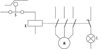
This channel uses switch S with positive action. The contactor K is supervised by the light L. The operator is advised that the normally open (NO) contacts stick by means of indication light L. The contactor K has forced guided contacts. (Note: Relays or contactors with forced guidance of contacts have, in comparison with usual relays or contactors, a special cage made from insulating material so that if normally closed (NC) contacts are closed, all NO contacts have to be opened, and vice versa. This means that by use of NC contacts a check may be made to determine that the working contacts are not sticking or welded together.)
Category 2
Category 2 provides for automatic detection of failures. Automatic failure detection has to be generated before each dangerous movement. Only if the test is positive may the movement be performed; otherwise the machine will be stopped. Automatic failure detection systems are used for light barriers to prove that they are still working. The principle is illustrated in figure 1.
Figure 11. Circuit including a failure detector

This control system is tested regularly (or occasionally) by injecting an impulse to the input. In a properly working system this impulse will then be transferred to the output and compared to an impulse from a test generator. When both impulses are present, the system obviously works. Otherwise, if there is no output impulse, the system has failed.
Category 3
Circuitry has been previously described under Example 3 in the Safety section of this article, figure 8.
The requirement—that is, automatic failure detection and the ability to perform the safety function even if one failure has occurred anywhere—can be fulfilled by two-channel control structures and by mutual supervising of the two channels.
For machine controls only, the dangerous failures have to be investigated. It should be noted that there are two kinds of failure:
- Non-dangerous failures are those that, after their occurrence, cause a “safe state” of the machine by providing for switching off the motor.
- Dangerous failures are those that, after their occurrence, cause an “unsafe state” of the machine, as the motor cannot be switched off or the motor starts to move unexpectedly.
Category 4
Category 4 typically provides for the application of a dynamic, continuously changing signal on the input. The presence of a dynamic signal on the output means running (“1”), and the absence of a dynamic signal means stop (“0”).
For such circuitry it is typical that after failure of any component the dynamic signal will no longer be available on the output. (Note: The static potential on the output is irrelevant.) Such circuits may be called “fail-safe”. All failures will be disclosed immediately, not after the first change (as in Category 3 circuits).
Further comments on control categories
Table 1 has been developed for usual machine controls and shows the basic circuit structures only; according to the machine directive it should be calculated on the assumption that only one failure will occur in one machine cycle. This is why the safety function does not have to be performed in the case of two coincident failures. It is assumed that a failure will be detected within one machine cycle. The machine will be stopped and then repaired. The control system then starts again, fully operable, without failures.
The first intent of the designer should be not to permit “standing” failures, which would not be detected during one cycle as they might later be combined with newly occurring failure(s) (failure cumulation). Such combinations (a standing failure and a new failure) can cause a malfunction of even Category 3 circuitry.
In spite of these tactics, it is possible that two independent failures will occur at the same time within the same machine cycle. It is only very improbable, especially if highly reliable components have been used. For very high-risk applications, three or more subchannels should be used. This philosophy is based on the fact that the mean time between failures is much longer than the machine cycle.
This does not mean, however, that the table cannot be further expanded. Table 1 is basically and structurally very similar to the Table 2 used in EN 954-1. However, it does not try to include too many sorting criteria. The requirements are defined according to the rigorous laws of logic, so that only clear answers (YES or NO) can be expected. This allows a more exact assessment, sorting and classification of submitted circuitry (safety-related channels) and, last but not least, significant improvement of assessment reproducibility.
It would be ideal if risks could be classified in various risk levels and then a definite link established between risk levels and categories, with this all independent of the technology in use. However, this is not fully possible. Early after creating categories it became clear that even given the same technology, various questions were not sufficiently answered. Which is better: a very reliable and well-designed component of Category 1, or a system fulfilling the requirements of Category 3 with poor reliability?
To explain this dilemma one must differentiate between two qualities: reliability and safety (against failures). They are not comparable, as both these qualities have different features:
- The component with highest reliability has the unpleasant feature that in the event of failure (even if highly improbable) the function will cease to perform.
- Category 3 systems, where even in case of one failure the function will be performed, are not safe against two failures at the same time (what may be important is whether sufficiently reliable components have been used).
Considering the above, it may be that the best solution (from the high-risk point of view) is to use highly reliable components and configure them so that the circuitry is safe against at least one failure (preferably more). It is clear that such a solution is not the most economical. In practice, the optimization process is mostly the consequence of all these influences and considerations.
Experience with practical use of the categories shows that it is rarely possible to design a control system that can utilize only one category throughout. Combination of two or even three parts, each of a different category, is typical, as illustrated in the following example:
Many safety light barriers are designed in Category 4, wherein one channel works with a dynamic signal. At the end of this system there usually are two mutually supervised subchannels which work with static signals. (This fulfils the requirements for Category 3.)
According to EN 50100, such light barriers are classified as Type 4 electro-sensitive protective devices, although they are composed of two parts. Unfortunately, there is no agreement how to denominate control systems consisting of two or more parts, each part of another category.
Programmable Electronic Systems (PESs)
The principles used to create table 1 can, with certain restrictions of course, be generally appled to PESs too.
PES-only system
In using PESs for control, the information is transferred from the sensor to the activator through a large number of components. Beyond that, it even passes “through” software. (See figure 12).
Figure 12. A PES system circuit
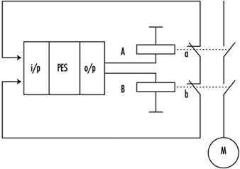
Although modern PESs are very reliable, the reliability is not as high as may be required for processing safety functions. Beyond that, the usual PES systems are not safe enough, since they will not perform the safety-related function in case of a failure. Therefore, using PESs for processing of safety functions without any additional measures is not permitted.
Very low-risk applications: Systems with one PES and additional measures
When using a single PES for control, the system consists of the following primary parts:
Input part
The reliability of a sensor and input of a PES can be improved by doubling them. Such a double-system input configuration can be further supervised by software to check if both subsystems are delivering the same information. Thus the failures in the input part can be detected. This is nearly the same philosophy as required for Category 3. However, because the supervising is done by software and only once, this may be denominated as 3- (or not as reliable as 3).
Middle part
Although this part cannot be well doubled, it can be tested. Upon switching on (or during operation), a check of the entire instruction set can be performed. At the same intervals, the memory can also be checked by suitable bit patterns. If such checks are conducted without failure, both parts, CPU and memory, are obviously working properly. The middle part has certain features typical of Category 4 (dynamic signal) and others typical of Category 2 (testing performed regularly at suitable intervals). The problem is that these tests, in spite of their extensiveness, cannot be really complete, as the one-PES system inherently does not allow them.
Output part
Similar to an input, the output (including activators) can also be doubled. Both subsystems can be supervised with respect to the same result. Failures will be detected and the safety function will be performed. However, there are the same weak points as in the input part. Consequently, Category 3 is chosen in this case.
In figure 13 the same function is brought to relays A and B. The control contacts a and b, then informs two input systems whether both relays are doing the same work (unless a failure in one of the channels has occurred). Supervising is done again by software.
Figure 13. A PES circuit with a failure-detection system
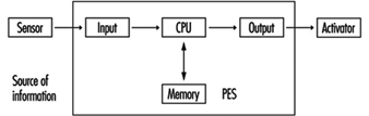
The whole system can be described as Category 3-/4/2/3- if properly and extensively done. Nevertheless, the weak points of such systems as above described cannot be fully eliminated. In fact, improved one PESs are actually used for safety-related functions only where the risks are rather low (Hölscher and Rader 1984).
Low- and medium-risk applications with one PES
Today almost every machine is equipped with a PES control unit. To solve the problem of insufficient reliability and usually insufficient safety against failure, the following design methods are commonly used:
- In relatively simple machines such as lifts, the functions are divided into two groups: (1) the functions that are not related to safety are processed by the PES; (2) the safety-related functions are combined in one chain (safety circuit) and processed outside of the PES (see figure 14).
Figure 14. State of the art for stop category 0
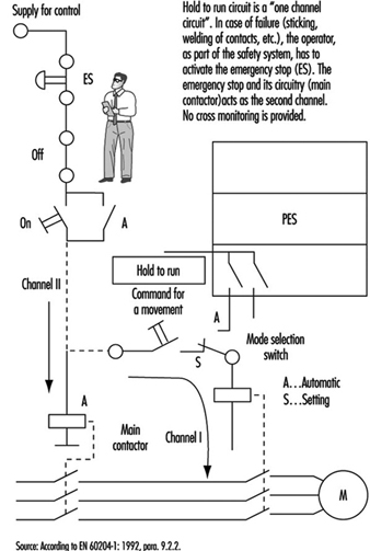
- The method given above is not suitable for more complex machines. One reason is that such solutions usually are not safe enough. For medium-risk applications, solutions should fulfil the requirements for category 3. General ideas of how such designs may look are presented in figure 15 and figure 16.
Figure 15. State of the art for stop category 1

Figure 16. State of the art for stop category 2

High-risk applications: systems with two (or more) PESs
Aside from complexity and expense, there are no other factors that would prevent designers from using fully doubled PES systems such as Siemens Simatic S5-115F, 3B6 Typ CAR-MIL and so on. These typically include two identical PESs with homogenous software, and assume the use of “well-tried” PESs and “well-tried” compilers (a well-tried PES or compiler can be considered one that in many practical applications over 3 or more years has shown that systematic failures have been obviously eliminated). Although these doubled PES systems do not have the weak points of single-PES systems, it does not mean that doubled PES systems solve all problems. (See figure 17).
Figure 17. Sophisticated system with two PESs
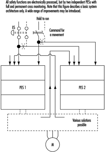
Systematic Failures
Systematic failures may result from errors in specifications, design and other causes, and may be present in hardware as well as in software. Double-PES systems are suitable for use in safety-related applications. Such configurations allow the detection of random hardware failures. By means of hardware diversity such as the use of two different types, or products of two different manufacturers, systematic hardware failures could be disclosed (it is highly unlikely that an identical hardware systematic failure would occur in both PES).
Software
Software is a new element in safety considerations. Software is either correct or incorrect (with respect to failures). Once correct, software cannot become instantly incorrect (as compared to hardware). The aims are to eradicate all errors in the software or to at least identify them.
There are various ways of achieving this goal. One is the verification of the program (a second person attempts to discover the errors in a subsequent test). Another possibility is diversity of the software, wherein two different programs, written by two programmers, address the same problem. If the results are identical (within certain limits), it can be assumed that both program sections are correct. If the results are different, it is presumed that errors are present. (N.B., The architecture of the hardware naturally must also be considered.)
Summary
When using PESs, generally the same following basic considerations are to be taken in account (as described in the previous sections).
- One control system without any redundancy may be allocated to Category B. One control system with additional measures may be Category 1 or even higher, but not higher than 2.
- A two-part control system with mutual comparison of results may be allocated to Category 3. A two-part control system with mutual comparison of results and more or less diversity may be allocated to Category 3 and is suitable for higher-risk applications.
A new factor is that for the system with a PES, even software should be evaluated from the correctness point of view. Software, if correct, is 100% reliable. At this stage of technological development, the best possible and known technical solutions will probably not be used, since the limiting factors are still economic. Furthermore, various groups of experts are continuing to develop the standards for safety applications of PESs (e.g., EC, EWICS). Although there are various standards already available (VDE0801, IEC65A and so on), this matter is so broad and complex that none of them may be considered as final.
Barbering and Cosmetology
General Profile
It has been estimated that over a million people work in approximately 150,000 salons and barber shops in the United States. These men and women, barbers and cosmetologists (also referred to as “technicians”), perform a wide range of services, including shaving; cutting and styling hair; giving manicures and pedicures; applying artificial nails; and performing a variety of chemical hair processes including bleaching, colouring, hair relaxing and permanent waving. In addition, some technicians provide facial treatments and removal of body hair.
Technicians may be exposed to a variety of potential health and safety hazards on the job, including:
Chemicals. According to an analysis conducted by the US National Institute for Occupational Safety and Health (NIOSH), 30% of the nearly 3,000 chemicals used in cosmetology are classified by the US government as toxic substances. Ventilation in many shops is often inadequate to eliminate chemical exposure.
Diseases. Because of their close contact with clients, technicians may be exposed to a variety of infectious diseases, ranging from colds and flu to impetigo, chicken pox and hepatitis.
Ergonomic hazards. Barbers and cosmetologists also suffer from a range of musculoskeletal disorders associated with repetitive motion, prolonged standing, cramped work spaces and poorly designed tools and equipment.
Scheduling. Working hours may be irregular and extended. Many technicians work in “split shifts”, splitting their work day to cover 12 to 14 hours of client services.
Other problems. These include poor housekeeping and electrical and fire hazards.
As a result of exposure to these and other hazards, an increasing number of people are being forced to leave their chosen profession. A recent study by Nellie Brown, director of the Chemical Hazards Information Program at Cornell University, found that 20% of US hair stylists leave their jobs because of work-related illness (New York Times Magazine, 7 March 1993).
Despite increasing evidence of risk, there are few regulations protecting barbers and cosmetologists. In the United States, cosmetic products are regulated by the Food and Drug Administration (FDA), which is oriented towards consumer protection and has a limited ability to address worker health and safety issues. Like regulatory agencies in many countries, the FDA does not require product manufacturers to conduct safety tests before public marketing, to list ingredients on the labels of products sold for professional use only or to give the FDA information on consumer complaints. Nor does the FDA routinely test products on its own initiative; any testing done by the FDA focuses on risks to consumers, not workers, although workers may be at greater risk due to their daily and prolonged use of cosmetic chemicals.
Attempts to regulate this industry are further complicated by the differing local, national and international definitions of the tasks barbers and cosmetologists perform. In the United States, licensing requirements vary from state to state. Many countries have no licensing requirements at all.
Major Processes and Hazards
Chemical hazards
Barbers and cosmetologists are exposed to a wide variety of chemicals during the course of a working day. Technicians are at risk for absorbing chemicals through the skin or eyes, inhaling dangerous vapours or particulates and ingesting toxins that have contaminated food, drink or cigarettes. Some guidelines for reducing hazardous exposure are given in figure 1 .
Figure 1. Reducing exposure to chemical hazards.
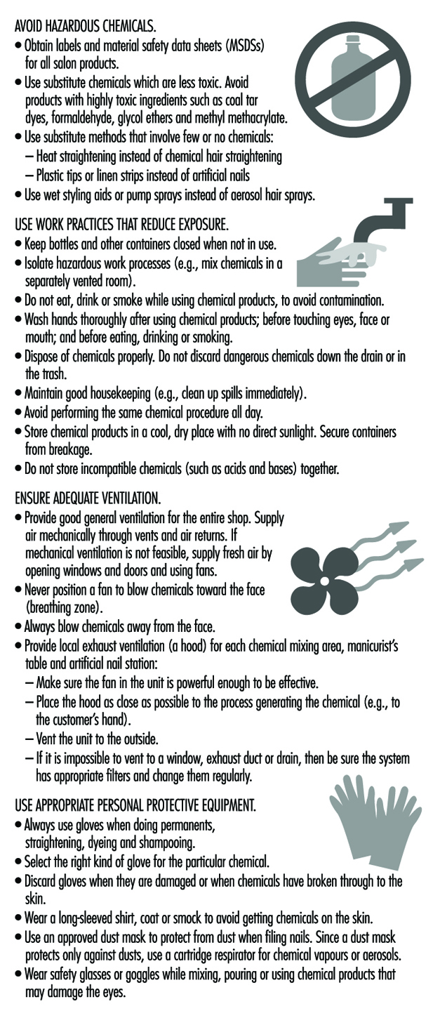
Chemicals can affect the body in different ways depending on the concentration of the chemical in a product; how toxic the chemical is; the route by which it enters the body (inhalation, skin contact, ingestion); and the length of time of the exposure. Individual characteristics, such as general health status, pregnancy and smoking, can also affect a person’s risk.
There are thousands of different chemicals associated with cosmetology processes. In order to determine the specific chemicals contained in a product and their effects, it is important that technicians have access to, and understand, product labels and material safety data sheets (MSDSs).
Common chemical processes
Colouring hair. Hair colouring solutions are applied manually to the hair with an applicator bottle or brush. It also is becoming very common for clients to request an eyebrow or eyelash tints.
Chemicals used in hair colouring include synthetic organic colorants, complex metallic colorants and vegetable dyes. Synthetic hair colorants often include permanent oxidative dyes which use hydrogen peroxide to oxidize aromatic diamines. These chemicals are eye, nose and throat irritants. Synthetic organic hair dyes containing an amine group are also among the most frequent causes of allergic sensitization. Metallic dyes may include lead-containing compounds.
Coal tar-based hair dyes may contain mutagens. Hair dyes which have been found to be mutagenic in in vitro testing pose uncertain human health risks. However, the production of non-mutagenic hair dyes appears to be possible and should be encouraged. For example, henna, a vegetable dye, is one of the oldest hair dyes and is not known to be either a mutagen or a carcinogen.
Bleaching hair. Bleaching solutions are applied manually with an applicator bottle or brush. These solutions may contain hydrogen peroxide, sodium peroxide, ammonium hydroxide, ammonium persulphate or potassium persulphate. These chemicals can cause skin, eye, nose, throat or lung irritation. Persulphate bleach powders have also been associated with asthma among cosmetologists (Blainey et al. 1986).
Permanent waving. Permanent waves usually involve several steps: washing the hair; rolling the hair in curlers; applying a thioglycolate or similar solution; and rinsing and neutralizing with an oxidizing agent. Water sprays may also be used.
Permanent-wave solutions may contain alcohol, bromates, sodium hydroxide, boric acid (perborate or borate), ammonium thioglycolate or glycerol monothioglycolate. Some of these chemicals may cause central nervous system effects (headache, dizziness, nausea, drowsiness); eye, nose and throat irritation; lung problems (breathing difficulty or coughing); skin irritation; burns; or allergic reactions (stuffy or runny nose, sneezing, asthma or allergic dermatitis).
Manicures, pedicures and artificial nails. Nail care involves soaking the cuticles in softening agents, using nail clippers, using emery boards or nail files to file the nails, using hand lotions and applying and removing polish. Artificial nails (acrylics, gels, fibreglass, porcelains and fabric wraps and tips) may be brushed onto the nail or attached to it with glue. They are allowed to harden and then filed to the desired shape.
The many chemicals found in nail products include acetone, ethyl methacrylate and other acrylates, methyl ethyl ketone, ethyl acetate, lanolin and dimethyl-p-toluidine. These can cause skin, eye, nose, throat and lung irritation, as well as central nervous system effects. Some nail products also contain formaldehyde, associated with allergies as well as cancer with long term use. Some products contain glycol ethers, xylene and toluene, all linked to reproductive problems in laboratory animals.
The use of methyl methacrylate (MMA) in artificial nail products was banned in the United States in 1974. Despite the ban, this chemical continues to be used. A 1982 study found that methyl methacrylate was present in 8 of 29 artificial nail products, and a 1986 study found measurable levels of MMA in the air of some nail salons. This chemical, if in contact with the skin, can cause tingling, numbness and whitening of the fingers. It also causes skin allergy in many people. An allergy to MMA can result in cross-sensitivity to other more commonly used methacrylates. In some products MMA has been replaced by other acrylates that may also be sensitizers. Figure 2 shows a downdraft table designed to minimize a manicurist’s exposure to the chemicals.
Figure 2. A modified commercial downdraft manicure table for application of artificial fingernails.
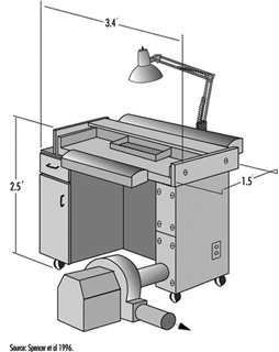
Washing and styling hair. Hair washing involves shampooing and rinsing with water. During this service, conditioners and other hair treatment products may also be applied. Hair drying is done in many ways: drying manually with towels, using a hand-held dryer or having the client sit under a fixed dryer. Styling generally involves the use of gels, creams or aerosol sprays. Washing the hair is often the first step for other services such as setting the hair, hair colouring and permanent waving. In large salons, one person may be assigned the job of washing clients’ hair, and do nothing other than that.
Shampoos and conditioners may contain alcohol, petroleum distillates and formaldehyde. All have been linked to dermatitis and allergies, including asthma. Long-term use of formaldehyde has also been linked to cancer.
Aerosol hair sprays may contain polyvinylpyrrolidone, which has been associated with lung and other respiratory diseases, including thesaurosis. They also contain a variety of solvents.
Straightening hair. Hair-straightening or hair-relaxing solutions are applied to the hair with a brush; then the hair is stretched to relax the natural curl. Hair straightener may contain sodium hydroxide, hydrogen peroxide, bromates, ammonium, thioglycolate and glycerol monothioglycolate. These chemicals may cause eye, nose and throat irritation, central nervous system effects and dermatitis.
Other chemical processes. A variety of cosmetics, including face creams and powders, mascara, eye liners, lipsticks and other products, may also be applied by cosmetologists. These can contain a wide variety of solvents, dyes, pigments, preservatives, oils, waxes and other chemicals that can cause skin allergies and/or irritation.
Cosmetologists may also remove body hair. Hair removal treatments can involve the application of hot wax and use of chemical depilatory products. These products often contain alkaline ingredients that can cause dermatitis.
Ergonomic hazards
Barbers and cosmetologists are at risk for musculoskeletal disorders due to the physical demands of their work and to poorly designed equipment, tools and work spaces. Such disorders can include:
- Wrist and hand problems, such as tendinitis and carpal tunnel syndrome. Risk factors include bending and twisting of the wrist while cutting and styling hair, holding hair dryers and using a round brush or curling iron. These disorders are also linked to forceful gripping or pinching caused by cutting with dull and/or poorly fitting shears.
- Shoulder problems, including tendinitis and bursitis. These are associated with constant reaching for supplies, or holding arms above shoulder height while cutting or styling hair. See figure 3.
- Neck and back problems, ranging from common aches and pains to serious conditions such as pinched nerves and ruptured discs. These are associated with frequent bending or twisting during activities such as shampooing, cutting hair below ear level, and performing manicures and pedicures.
- Foot and leg problems, including swelling, calluses and varicose veins. These may occur as a result of long periods of standing on hard floors in shoes with poor arch support.
Figure 3. Working with arms above shoulder level in a hairdressing salon in Zimbabwe.

Preventing musculoskeletal disorders
To prevent musculoskeletal disorders, it is important to apply ergonomic principles to the design of tasks, tools and workstations. Ergonomics is the science of adapting the workplace to the needs of the human body. It suggests ways to minimize awkward postures and repetitive motions, as well as the use of excessive force. It maximizes safety, health and comfort.
Ergonomic solutions may include:
- Adjustable furniture. For example, client chairs are available that can be raised, lowered and swiveled. Manicurist chairs are available with back support, armrests and seat pans that can be tilted to accommodate forward bending.
- Shears that are sharp, well-lubricated and designed to fit the individual’s hand.
- Curling irons and hair dryers with flexible handles. These can be used without excessive bending or twisting of the wrist.
- Free-standing sinks that allow technicians to wash hair without twisting and bending their backs.
- Rolling seats or stools that allow technicians to perform many procedures while seated, or to alternate between sitting and standing.
- Proper workstation designs such as storing commonly used supplies within easy reach; providing cushioned floor mats; and ensuring that cabinets are at the correct height to minimize reaching or bending.
- Client scheduling that varies the tasks and processes that a technician performs throughout the day.
- Training for technicians in good body mechanics and work practices such as proper lifting methods; bending at the hips instead of the waist; and using hair-cutting techniques that minimize reaching and bending of the wrist.
Infectious diseases
Work performed by barbers and cosmetologists involves close contact with clients. Understanding how infectious diseases are transmitted will help technicians prevent infection. Infectious diseases may be spread in the salon in the following ways:
- Through the air (e.g., upper respiratory illnesses such as colds and flu)
- Through contaminated water or food (e.g., hepatitis A, salmonella and giardia)
- Through insect or animal bites (e.g., lice)
- Through direct skin contact with infected persons (e.g., scabies, lice, ringworm, impetigo, herpes simplex, colds and chickenpox)
- Rarely, through exposure to the blood of an infected person (e.g., hepatitis B and HIV/AIDS)
While there is no recorded case of a barber or cosmetologist becoming infected with HIV/AIDS on the job, and work-related hepatitis B infection is extremely rare in these occupations, exposure to these bloodborne pathogens could possibly occur in rare instances of blood contact. Possible sources of exposure could include puncturing the skin with tools that carry infected blood (razors, tweezers, tattoo needles or clippers), or infected blood entering the body through an open wound, sore or skin rash.
This is one reason that shaving clients with razors has become uncommon in many countries. In addition to the risk to technicians, there is the possibility of skin and other infections being transferred from one client to another through unsterilized equipment.
Exposure to harmful organisms can be prevented by taking simple precautions:
- Hands should be washed frequently with soap and water.
- Latex gloves should be worn to protect technician and client if either has sores, lesions or skin rashes.
- Sharp instruments should be handled carefully and disposed of in approved puncture-proof containers.
- All tools, equipment and surfaces should be disinfected properly.
- Towels should be sanitized.
- Workers should be vaccinated against hepatitis B.
Other hazards
Fire hazards
Some products used in the salon may contain flammable or combustible chemicals. Sources of ignition can include flame from a cigarette, match or burner; a spark from a light switch, electric plug or frayed cord; or a hot object such as a curling iron, stove, light bulb or hotplate. To prevent accidents, it should be made sure that chemicals are used and stored properly. Flammables and combustibles should be kept away from flames, sparks or hot objects, and electrical equipment should be checked for broken or frayed cords that might spark or get hot. Each shop should also have a fire-prevention and evacuation plan, and appropriate and functioning fire extinguishers.
General housekeeping
Salons are often cramped and crowded work environments. Overstocked shelves may be unstable. Technicians may be at risk for slips and falls as a result of spilled liquids, poorly stored equipment or poorly positioned cords or wires. Narrow, crowded aisles limit workers’ ability to move freely without obstruction. All shops should practice good housekeeping, including: keeping aisles clear, cleaning up spills immediately, storing heavy objects on low shelves and making sure people can move freely through their workspace.
Electrical hazards
Electrical devices in the salon can include hair clippers, hair dryers, facial machines and electrolysis equipment and they should be checked for frayed wires and proper grounding. Since electrical equipment and outlets are often within splash range of water, red ground fault circuit interrupters to prevent shock should be used.
Health Problems and Disease Patterns
Skin diseases
Irritant and allergic dermatitis of the hands alone, or of hands and face together, is a common problem, experienced by 10 to 20% of cosmetologists (van der Walle and Brunsveld 1994). It often produces a characteristic rash in the spaces between the fingers. Signs of dermatitis generally include redness, drying and cracking on the skin of the hands. Eczema of the tips of the fingers may also occur, with ridging of the nail folds. Younger workers appear to be at highest risk, possibly because those with lower seniority tend to be assigned most often to shampooing and permanent-waving jobs. Most frequent causes of allergic skin rash in cosmetologists include glycerol thioglycolate, ammonium thioglycolate, nickel sulphate, ammonium persulphate preservatives and hair dyes (p-phenylenediamine or resorcinol) (Villaplana, Romaguera and Grimalt 1991).
In most cases, once an allergic dermatitis develops it does not improve, even with the wearing of gloves. Rubber latex glove use may itself be a significant risk factor for allergic responses, and vinyl gloves may need to be substituted if latex allergy develops. If one worker in a salon develops latex allergy, the entire salon may need to become latex-free to protect that worker from repeated allergic responses.
Other skin diseases of hairdressers include granuloma from hair implantation, and hot water burns. Also, varicose veins may result from the prolonged standing common to this occupation. Sharp tools such as scissors, shaving equipment and electric hair-cutting tools can cause skin lacerations. Such cuts may predispose the cosmetologist to dermatitis due to chemical exposures.
Lung problems
Allergic rhinitis (“hay fever”) and asthma have been associated with exposure to permanent-wave solution (Schwartz, Arnold and Strohl 1990), and in particular to ammonium persulphate (Gamboa et al. 1989). Hair bleach as well as henna (Starr, Yunginger and Brahser 1982) have been associated with occupational asthma in cosmetologists.
Reproductive health
A recent study found a moderately increased risk of spontaneous abortion among cosmetologists who worked full time and performed a large number of chemical services. The use of formaldehyde and exposure to manicuring and nail-sculpting chemicals were specifically associated with an increased risk of spontaneous abortion (John, Savitz and Shy 1994).
Cancer
Cosmetologists have been found to have a possible increased risk of developing certain types of cancer, including non-Hodgkin’s lymphoma (Zahm et al. 1992; Pearce 1992), bladder/urothelial cancer (Steineck et al. 1990) and breast cancer (Koenig 1994).
Indoor Cleaning Services
General Profile
Cleaning consists of dusting, washing and polishing surfaces; washing walls; mopping, sweeping and polishing floors; as well as disposing of waste and waste water. It is done in offices, public and commercial buildings, homes and factories. It may be done in confined spaces with little ventilation and in spaces not designed with cleaning in mind. Cleaners may be independent or be employed by the enterprise which owns the facilities being cleaned, or they may work for private contractors. Those who clean may be called cleaners, housekeepers, chars, custodians or janitors, depending on the spaces cleaned and the details of the assigned tasks. For example, janitors and custodians may combine cleaning with maintenance and repair work.
Cleaners have usually worked relatively autonomously, compared to other employment categories of similar prestige. Inspection is done by supervisors, although the users of the cleaned spaces also comment on the cleaners’ work. Workers tend to order the tasks themselves and develop their own procedures (Messing, Haëntjens and Doniol-Shaw 1993). However, in commercial spaces in North America, cleaners’ routes have increasingly been determined using software programmed to take account of furniture, floor surfaces and crowding. The desired frequency of operations, area to be cleaned and time estimated for the type of area are used to calculate the total time required. Inspection may be done using a computer-programmed spot check procedure. Some of these procedures may severely underestimate the task as performed in shared space, especially if the inventory is not brought regularly up to date (Messing, Chatigny and Courville 1996).
In Canada, cleaning is the eighth most common profession of men and the tenth most common profession of women; women make up 46% of the profession (Armstrong and Armstrong 1994). In France in 1991, 229,000 cleaners worked for 9,000 cleaning companies; about a third were immigrants and 64% were women (Bretin 1994). In Denmark 85% of the 130,000 cleaners are women (Nielsen 1995). In some countries, tasks in factories and services have often been divided into “light” and “heavy”, assigned formally or informally to female and male workers respectively, who may be paid at different rates (Government of Quebec 1994). Women may dust and polish surfaces, clean bathrooms and empty wastebaskets while men sweep, mop and polish floors and carry waste to incinerators (Messing, Haëntjens and Doniol-Shaw 1993; Messing, Doniol-Shaw and Haëntjens 1993; Messing, Chatigny and Courville 1996). In other countries, men and women can be assigned to all cleaning tasks (Nielsen 1995; Hagner and Hagberg 1989). Cleaners are often relatively old compared to other workers (Bretin et al. 1992; Messing 1991; Nielsen 1995).
Risk Factors and Prevention Strategies
Cleaning may be done with hand-held tools such as brushes, brooms, rags and mops, or may be aided by machines. A variety of chemicals are used to dissolve dirt and to make surfaces appear clean and shiny. The difficulty of the task varies according to the type of surface (rough, smooth, pitted), the height and geometry of the objects cleaned, the degree of crowding of spaces and the vocations exercised in the spaces cleaned. In some places, the need for cleaning may be reduced or eliminated by design changes in the object cleaned (such as self-flushing toilets).
Musculoskeletal load
Cleaning, particularly cleaning furniture and bathrooms and emptying wastebaskets, involves rapid postural changes and many awkward and constrained postures (see table 1). Many objects must be cleaned, at a variety of heights; a typical sequence observed for dusting in a hospital room was: table (81 cm), television (196 cm), table (81 cm), telephone (81 cm), lamp (extends to 188 cm), table foot (11 cm), chair (46 cm), screen (81 cm), armchair (46 cm), window ledge (89 cm), wall sphygmomanometer (154 cm), chair legs (floor to 46 cm), oxygen fixture (137 cm) (Messing, Chatigny and Courville 1995).
Table 1. Postures observed during dusting in a hospital.
|
Activity |
Duration |
Extension (%) |
Neutral (%) |
Bending <45º (%) |
Bending ≥45º (%) |
Not observable |
|
Clean nurse station |
3 m, 26 s |
— |
13.6 |
86.4 |
— |
— |
|
Waste-basket (3) |
1 m, 26 s |
— |
19.8 |
71.1 |
9.2 |
— |
|
Bath (2) |
5 m, 17 s |
2.8 |
26.6 |
63.1 |
7.5 |
— |
|
Bathroom corridor (2) |
3 m, 53 s |
6.6 |
18.6 |
71.0 |
3.8 |
0.3 |
|
Clean rooms |
8 m, 45 s |
3.7 |
29.8 |
60.1 |
2.9 |
3.5 |
|
Reception area |
3 m, 13 s |
— |
24.7 |
74.4 |
— |
0.9 |
|
Secretaries’ office |
10 m, 20 s |
3.6 |
32.0 |
59.7 |
0.3 |
4.4 |
|
Overall |
36 m, 20 s |
3.0 |
26.4 |
65.8 |
2.7 |
2.2 |
Source: Messing, Chatigny and Courville 1995.
Floor cleaning requires repeated movements (fundamental cycle time of 1 to 2 seconds in the Sogaard, Fallentin and Nielsen (1996) study) and a sustained moderate bending of the back. Constant pressure is exerted by the hands to push vacuum cleaners or buffers, tasks requiring forces near 10 kg (Messing, Chatigny and Courville 1996). Sogaard, Fallentin and Nielsen (1996) found mean back bending during floor mopping to be 28º and mean neck bending to be 51º. Hagner and Hagberg (1989) also noted static muscular loads especially at the shoulder joint. Nordin et al. (1986) found extensive forward trunk bending in a simulated janitorial task involving floor mopping. Cleaning floors and objects is usually done with repeated movements. Sogaard (1994) suggests that the sustained repetitive motions with infrequent pauses in activity may exhaust the relatively small numbers of muscle fibres involved and result in muscular disorders.
In order to clean, many objects must be moved. During 66 minutes cleaning and polishing floors, 0.7 objects had to be moved per minute, with weights up to 10 kg; during 23 minutes of dusting, 3.7 objects were moved per minute, with weights up to 2 kg (Messing, Chatigny and Courville 1995).
Winkel et al. (1983) and Hagner and Hagberg (1989) note that increasing specialization and standardization have reduced the number of opportunities to vary body movements and postures during cleaning work. It is therefore important to provide adequate break time. Formal or informal division of tasks according to sex may increase the likelihood of musculoskeletal problems by decreasing the variation in movements (Messing, Haëntjens and Doniol-Shaw 1993).
Cardiovascular load
The cardiovascular load can be quite heavy. Johansson and Ljunggren (1989) recorded the heart rate of female cleaners during office or toilet cleaning at 123 beats/minute, 65% of the maximum for their average age of 29.8 years (corresponding to about 35% of their estimated maximal oxygen uptake or VO2 max, close to that of construction workers). Swabbing or mopping resulted in similar heart rates of 122 to 127 beats/minute. Hagner and Hagberg (1989) found a high level of oxygen consumption (up to 40% of the VO2 max) among cleaners doing floor mopping under experimental conditions. Sogaard (1994) found that relative cardiovascular strain of female school cleaners measured in the workplace was 53% of the VO2 max.
To prevent musculoskeletal problems and decrease the cardiovascular load, workload should be appropriate and sufficient rest time should be allowed. Attention should be paid to ease of cleaning when spaces and procedures are being designed and when furnishings are purchased. Vacuuming requires less force if carpets are carefully laid so as not to wrinkle when the vacuum cleaner is passed. The use of adequate tools is important. For example, extendable brushes for dusting can reduce the necessity to reach or climb. Prolonged bending can be minimized if efficient chemicals and tools make it possible to clean quickly, and if cleaning is frequent enough so that dirt does not become hardened.
The common practice of reducing the rate of ventilation in buildings during the evening or night hours, when cleaning is done, reduces air quality for cleaning workers who work during these times and should be avoided. To prevent overwork in the case where cleaning is planned using purchased software, careful observation and verification should be done in order to make sure that times allotted are realistic and take into account multiple use of spaces cleaned. Inventories of rooms and objects cleaned should be updated frequently.
Procedures and apparatus for emptying wastebaskets into bins, and bins into incinerators, have been developed so that manual lifting can be avoided.
Chemicals
Chemicals can be classed as soaps, detergents, disinfectants, porcelain cleaners, scouring powders, wax removers and strippers, solvents, pesticides and drain cleaners. They may contain other ingredients such as fragrances and colouring agents. There may be surface skin contact or they may be inhaled or absorbed through the skin into the system. Damage to the skin, eyes, throat or lungs can result. The risk of exposure depends on the concentration of the chemical and how it is used. Sprays volatilize chemicals and increase exposure. Some chemicals are irritants at low concentration and corrosive at high concentration (acids, oxidizing agents or bases). Others are effective solvents or detergents which may damage the skin barrier and make it more vulnerable to other chemical agents. Still others contain metals (nickel, cobalt, chrome) or other substances which can act as allergens.
Cleaning agents are often sold at high concentrations and diluted on site for use. The common practice of using chemicals at a higher concentration than recommended, in the hope of cleaning more quickly or more efficiently, is a source of overexposure and should be remedied by proper education and by adjusting the workload. Mixing different chemicals can cause accidental intoxication or burns. Work with strong chemicals in poorly ventilated spaces can be a hazard for cleaners and should be avoided.
The Danish Product Register Data Base PROBAS contains information on 2,567 washing and cleaning agents. Of these, 70 are considered to be potentially harmful agents causing chronic or acute health damage, such as corrosives, carcinogens, reproductive toxicants, allergens and neurotoxic agents (Borglum and Hansen 1994). These agents are presented in table 2. A study of the PROBAS register found 33 contact allergens in cleaning agents (Flyvholm 1993).
Table 2. Dangerous chemicals used in cleaning.†
|
Chemical |
Health damage codes |
Other hazards |
|
Solvents |
||
|
Butylglycol |
N* |
|
|
Isopropyl benzene |
N |
|
|
Naphtha, white spirit, Stoddard solvent |
N,R |
|
|
Toluene |
N,R |
Flammable |
|
Ethanol |
R |
Flammable |
|
2-Ethoxyethanol |
N,R |
|
|
2-Methoxyethanol |
R |
|
|
1-Methyl-2-pyrrolido |
R |
|
|
Base oil, crude oil |
N |
|
|
Tetrachloroethylene |
N,R |
|
|
1,1,1-Trichloroethane |
N |
|
|
Xylene |
N,R* |
Flammable |
|
Butyldiglycol |
I |
|
|
Acids and bases |
||
|
Acetic acid |
C |
|
|
Ammonium hydroxide |
I |
Reacts with chlorine bleaches to liberate toxic gas |
|
Potassium hydroxide |
C |
|
|
Sodium carbonate |
I |
|
|
Sodium hydroxide |
C |
|
|
Phosphoric acid |
C |
|
|
Sulphuric acid |
C |
|
|
Residual monomers and impurities |
||
|
Formaldehyde |
A,K* |
|
|
Phenol |
N* |
|
|
Benzene |
K,R,N |
|
|
Acrylonitrile |
A,K |
|
|
Butylacrylate |
A |
|
|
Methylmethacrylate |
A,R |
|
|
Styrene |
R |
Flammable |
|
1-Propanol |
N |
Flammable |
|
Ethyl acrylate |
A,K* |
|
|
1,2-Ethylene diamine |
A |
|
|
Ethylene oxide |
A,K,R |
Flammable |
|
Propylene oxide |
K |
Flammable |
|
2-Methylaniline |
K |
|
|
2-Propyn-1-ol |
N |
|
|
Chelators |
||
|
Sodium EDTA (ethylene diamine tetraacetic acid) |
R |
|
|
Sodium NTA (nitrilotriacetic acid) |
K |
|
|
Anti-rusts |
||
|
2-Aminoethanol |
N |
|
|
Triethanolamine |
A |
|
|
Hexamethylene tetramine |
A |
|
|
2-Butyn-1,4-diol |
C,T |
|
|
Disodium metasilicate |
C,I |
|
|
2-(3H)-Benzothiazolethione |
A |
|
|
Disinfectants |
||
|
Borax |
R |
|
|
Disodium tetraborate |
R |
|
|
Morpholine |
N |
|
|
Benzalkonium chloride |
C |
|
|
Sodium dichloroisocyanurate |
I |
Reacts with acid to liberate toxic gas |
|
Sodium hypochlorite |
C |
Reacts with acid or ammonia to release toxic gases |
|
Preserving agents |
||
|
1,2-Bensisothiazol-3(2H)-one |
A |
|
|
5-Chlor-2-methyl-3-isothiazolone |
A |
|
|
2-Methyl-3-isothiazolone |
A |
|
|
2-Chloracetamide |
A |
|
|
p-Chlor-m-cresol |
A |
|
|
Hexahydro-1,3,5-tris- (2-hydroxyethyl)1,3,5-triazine |
A |
|
|
1,5-Pentadiol |
A |
|
|
2-Bromo-2-nitro-1,3-propanediol |
T |
|
|
Fillers |
||
|
Quartz |
K |
|
|
Silicon dioxide |
K |
|
|
Sodium hydrogen sulphate |
C |
|
|
Others |
||
|
Subtilisin (Enzyme) |
A |
|
|
Sodium saccharine |
K |
|
|
Ammonium peroxodisulphate (bleaching agent) |
A |
|
A = allergen; C = corrosive; I = irritant; K = carcinogen; N = neurotoxic agent; R = reproductive toxic agent; T = toxic if swallowed; * = danger dependent on concentration.
Determination of toxicity was done by the Danish Institute of Occupational Health. †Note that not all cleaning agents have been tested for all toxic properties, so that this list is not necessarily complete or comprehensive. Source: Summarized from Borglum and Hansen 1994. Cleaners who work in factories or hospitals may be exposed to chemicals (or biohazards) associated with the ongoing activities in the spaces they clean. If cleaners are not integrated into the training programmes and social network of the regular workforce, they may be less aware of these hazards than other workers. For example, one study showed that cleaners were the group most often exposed to harmful chemicals of all categories of hospital workers (Weaver et al. 1993). There is some controversy about the use of gloves for cleaning work. Gloves play an important role in protecting the skin from hazardous agents if they fit correctly and are made of impermeable and resistant materials. But wearing gloves constantly can keep perspiration from evaporating. The resulting damp area is a favourable growth medium for infectious agents. Wearing gloves was associated with skin problems in a large sample of Danish cleaners (Nielsen 1996). It is therefore best to wear gloves the minimum time compatible with protection. The necessity for wearing gloves can often be obviated by using tools with long handles, or by other changes in methods. Wearing cotton gloves under rubber or plastic gloves may reduce humidity and protect against allergies to some glove materials (Foussereau et al. 1982). Some hand creams may contain irritants and should be avoided (Hansen 1983). Several other practices diminish exposure to chemicals. When cleaning solutions are stored or prepared, there should be good ventilation, and procedures should permit preparation without any danger of touching or breathing the chemicals. The temptation to work with undiluted chemicals will diminish if workers have adequate time and implements. Also, cleaners may use undiluted chemicals or chemicals that have allergenic fragrances in order to signal to others that they have done their job. This can be done by other means, such as clear inspection procedures and communication links with other workers and with clients of cleaning services. Useful information on prevention of exposure to chemicals can be found in a handbook published by the City of New York (Michaels, undated). Other health risks Cleaners often work evening or night shifts, so as not to interfere with the other activities being carried out in the same spaces. They may therefore suffer the usual effects of shift work on biorhythms. In addition, they may risk violence if they work alone in isolated areas. Cleaners, particularly those who work outside regular building hours and/or who are not part of the regular personnel, may be ignored and excluded from the social network in their workplaces (Messing in press). They may not be given access to the appropriate facilities for breaks and meals. Aside from the psychological effects of exclusion, cleaners may be deprived of information on hazards routinely given to other workers, despite legal requirements in many jurisdictions to provide this information. Also, despite the importance of surface textures and design for their work, they and their supervisors may not be consulted when relevant purchasing and planning decisions are made. This is especially true if cleaning is contracted out. It is therefore important that a special effort be made to include cleaners in occupational health and safety promotion activities in the workplace. Information on characteristics of chemicals, on work procedures and on safety should be discussed with cleaners and clearly posted in the workplace. Health Effects and Disease Patterns Cleaners as a profession have poorer health than others (Nielsen 1995; ASSTSAS 1993; Sogaard 1994). Comparing cleaners with other workers, an analysis of the Quebec Health Survey found, after controlling for age, that women cleaners had the highest prevalence of chronic back problems and cardiopathies of all categories of women workers and that male cleaners had the highest prevalence of musculoskeletal problems and cardiopathies (Gervais 1993). Pregnant cleaners have an increased likelihood of miscarriage (McDonald et al. 1986), giving birth prematurely (McDonald et al. 1988) or bearing children with low birth weight (McDonald et al. 1987). Some large population-based epidemiological studies have found high cancer rates among cleaners. Rates of some brain tumours among US White men have been found to be especially high for cleaning service workers (Demers, Vaughan and Schommer 1991). Among women, invasive cervical cancer is almost five times more common among cleaners than other women (Savitz, Andrews and Brinton 1995). These results are attributed to chemical exposures, particularly solvents. Musculoskeletal problems are often encountered. In Denmark, Nielsen (1995) found that those who left cleaning had a reduced frequency of musculoskeletal symptoms compared to those who stayed in the profession. Cleaning was one of the five trades reporting the most shoulder/neck pain, tendovaginitis and low back pain (Sogaard, Fallentin and Nielsen 1996). A population-based epidemiological study found female cleaners to be particularly likely to have osteoarthritis of the knee, compared to other Swedish workers (Vingard et al. 1991). Cleaners in Quebec hospitals suffer almost twice as many occupational accidents and illnesses as the average Quebec health care worker: 23.8 compared to 13.9 per 100 full-time equivalent workers per year (ASSTSAS 1993). Most lesions involved the trunk or upper limbs (ASSTSAS 1993). Comparing male with female cleaners, a survey of cleaners in the Paris region in France found that men had more back pain and women had more joint pain (Opatowski et al. 1995). These differences are probably attributable to specificities in the tasks assigned to women and men cleaners (Messing, Haëntjens and Doniol-Shaw 1993; Messing, Doniol-Shaw and Haëntjens 1993; Messing, Chatigny and Courville 1996). Cleaners have a high level of skin problems, including dermatitis and eczema (Gawkrodger, Lloyd and Hunter 1986; Singgih et al. 1986). Point prevalences of skin diseases of 15 to 18%and a duration of employment prevalence of 39%have been found among large samples of hospital cleaners (Hansen 1983; Delaporte et al. 1990). Cleaners who spend more time with wet hands have more skin problems (Nielsen 1996). Cleaners may also be injured or infected by broken glass, needles or other sharp objects while handling waste (ASSTSAS 1993). Recently, occupational health specialists have noted symptoms of stress related to work among hospital cleaners, for which they suggest re-examination of the work process (Toivanen, Helin and Hänninen 1993). Low prestige of the profession may be a cause of distress for cleaners (Messing, in press). Accidents, infection and environmental contamination may be prevented by clear and well-publicized guidelines for disposal of dangerous waste in factories, hospitals, offices and public buildings. Since constraints placed on other workers may prevent them from paying full attention to prevention of hazards for cleaners, consultations between cleaners and other workers should be arranged, in order to decide on the appropriate size and placement of wastebaskets, waste separation and labelling. Cleaners should be included whenever waste disposal practices are being planned or reviewed so that realistic methods can be proposed.
" DISCLAIMER: The ILO does not take responsibility for content presented on this web portal that is presented in any language other than English, which is the language used for the initial production and peer-review of original content. Certain statistics have not been updated since the production of the 4th edition of the Encyclopaedia (1998)."