It is generally agreed that control systems must be safe during use. With this in mind, most modern control systems are designed as shown in figure 1.
Figure 1. General design of control systems
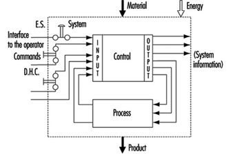
The simplest way to make a control system safe is to construct an impenetrable wall around it so as to prevent human access or interference into the danger zone. Such a system would be very safe, albeit impractical, since it would be impossible to gain access in order to perform most testing, repair and adjustment work. Because access to danger zones must be permitted under certain conditions, protective measures other than just walls, fences and the like are required to facilitate production, installation, servicing and maintenance.
Some of these protective measures can be partly or fully integrated into control systems, as follows:
- Movement can be stopped immediately should anybody enter the danger zone, by means of emergency stop (ES) buttons.
- Push-button controls permit movement only when the push-button is activated.
- Double-hand controls (DHC) permit movement only when both hands are engaged in depressing the two control elements (thus ensuring that hands are kept away from the danger zones).
These types of protective measures are activated by operators. However, because human beings often represent a weak point in applications, many functions, such as the following, are performed automatically:
- Movements of robot arms during the servicing or “teach-in” are very slow. Nonetheless, speed is continuously monitored. If, because of a control system failure, the speed of automatic robot arms were to increase unexpectedly during either the servicing or teach-in period, the monitoring system would activate and immediately terminate movement.
- A light barrier is provided to prevent access into a danger zone. If the light beam is interrupted, the machine will stop automatically.
Normal function of control systems is the most important precondition for production. If a production function is interrupted due to a control failure, it is at most inconvenient but not hazardous. If a safety-relevant function is not performed, it could result in lost production, equipment damage, injury or even death. Therefore, safety-relevant control system functions must be more reliable and safer than normal control system functions. According to European Council Directive 89/392/EEC (Machine Guidelines), control systems must be designed and constructed so that they are safe and reliable.
Controls consist of a number of components connected together so as to perform one or more functions. Controls are subdivided into channels. A channel is the part of a control that performs a specific function (e.g., start, stop, emergency stop). Physically, the channel is created by a string of components (transistors, diodes, relays, gates, etc.) through which, from one component to the next, (mostly electrical) information representing that function is transferred from input to output.
In designing control channels for safety-relevant functions (those functions which involve humans), the following requirements must be fulfilled:
- Components used in control channels with safety-relevant functions must be able to withstand the rigours of normal use. Generally, they must be sufficiently reliable.
- Errors in the logic must not cause dangerous situations. Generally, the safety-relevant channel is to be sufficiently failure proof.
- External influences (factors) should not lead to temporary or permanent failures in safety-relevant channels.
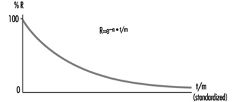
Reliability
Reliability is the ability of a control channel or component to perform a required function under specified conditions for a given period of time without failing. (Probability for specific components or control channels can be calculated using suitable methods.) Reliability must always be specified for a specific time value. Generally, reliability can be expressed by the formula in figure 2.
Figure 2. Reliability formula
Reliability of complex systems
Systems are built from components. If the reliabilities of the components are known, the reliability of the system as a whole can be calculated. In such cases, the following apply:
Serial systems
The total reliability Rtot of a serial system consisting of N components of the same reliability RC is calculated as in figure 3.
Figure 3. Reliability graph of serially connected components
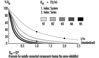
The total reliability is lower than the reliability of the least reliable component. As the number of serially connected components increases, the total reliability of the chain falls significantly.
Parallel systems
The total reliability Rtot of a parallel system consisting of N components of the same reliability RC is calculated as in figure 4.
Figure 4. Reliability graph of parallel connected components
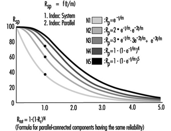
Total reliability can be improved significantly through the parallel connection of two or more components.
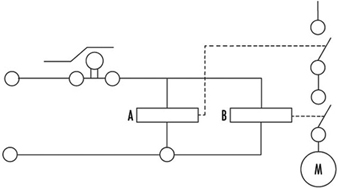
Figure 5 illustrates a practical example. Note that the circuitry will switch off the motor more reliably. Even if relay A or B fails to open its contact, the motor will still be switched off.
Figure 5. Practical example of figure 4
To calculate the total reliability of a channel is simple if all necessary component reliabilities are known and available. In the case of complex components (integrated circuits, microprocessors, etc.) the calculation of the total reliability is difficult or impossible if the necessary information is not published by the manufacturer.
Safety
When professionals speak about safety and call for safe machines, they mean the safety of the entire machine or system. This safety is, however, too general, and not precisely enough defined for the designer of controls. The following definition of safety may be practical and usable to designers of control circuitry: Safety is the ability of a control system to perform the required function within prescribed limits, for a given duration, even when anticipated fault(s) occur. Consequently, it must be clarified during the design how “safe” the safety-related channel must be. (The designer can develop a channel that is safe against first failure, against any one failure, against two failures, etc.) Furthermore, a channel that performs a function which is used to prevent accidents may be essentially reliable, but it does not have to be inevitably safe against failures. This may be best explained by the following examples:
Example 1
The example illustrated in figure 6 is a safety-relevant control channel performing the required safety function. The first component may be a switch that monitors, for example, the position of an access door to a dangerous area. The last component is a motor which drives moving mechanical parts within the danger area.
Figure 6. A safety-relevant control channel performing the required safety function
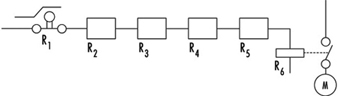
The required safety function in this case is a dual one: If the door is closed, the motor may run. If the door is open, the motor must be switched off. Knowing reliabilities R1 to R6, it is possible to calculate reliability Rtot. Designers should use reliable components in order to maintain sufficiently high reliability of the whole control system (i.e., the probability that this function may still be performed in, say, even 20 years should be accounted for in the design). As a result, designers must fulfil two tasks: (1) the circuitry must perform the required function, and (2) the reliability of the components and of the whole control channel must be adequate.
The following question should now be asked: Will the aforementioned channel perform the required safety functions even if a failure occurs in the system (e.g., if a relay contact sticks or a component malfunctions)? The answer is “No”. The reason is that a single control channel consisting only of serially connected components and working with static signals is not safe against one failure. The channel can have only a certain reliability, which guarantees the probability that the function will be carried out. In such situations, safety is always meant as failure related.
Example 2
If a control channel is to be both reliable and safe, the design must be modified as in figure 7. The example illustrated is a safety-relevant control channel consisting of two fully separated subchannels.
Figure 7. A safety-relevant control channel with two fully separate subchannels
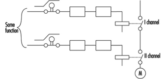
This design is safe against the first failure (and possible further failures in the same subchannel), but is not safe against two failures which may occur in two different subchannels (simultaneously or at different times) because there is no failure detection circuit. Consequently, initially both subchannels work with a high reliability (see parallel system), but after the first failure only one subchannel will work, and reliability decreases. Should a second failure occur in the subchannel still working, both will have then failed, and the safety function will no longer be performed.
Example 3
The example illustrated in figure 8 is a safety-relevant control channel consisting of two fully separate subchannels which monitor each other.
Figure 8. A safety-relevant control channel with two fully separate subchannels which monitor each other
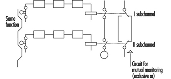
Such a design is failure safe because after any failure, only one subchannel will be non-functional, while the other subchannel remains available and will perform the safety function. Moreover, the design has a failure detection circuit. If, due to a failure, both subchannels fail to work in the same way, this condition will be detected by “exclusive or” circuitry, with the result that the machine will be automatically switched off. This is one of the best ways of designing machine controls—designing safety-relevant subchannels. They are safe against one failure and at the same time provide enough reliability so that the chances that two failures will occur simultaneously is minuscule.
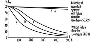
Redundancy
It is apparent that there are various methods by which a designer may improve reliability and/or safety (against failure). The previous examples illustrate how a function (i.e., door closed, motor may run; door opened, motor must be stopped) can be realized by various solutions. Some methods are very simple (one subchannel) and others more complicated (two subchannels with mutual supervising). (See figure 9.)
Figure 9. Reliability of redundant systems with or without failure detection
There is a certain redundancy in the complex circuitry and/or components in comparison with the simple ones. Redundancy can be defined as follows: (1) Redundancy is the presence of more means (components, channels, higher safety factors, additional tests and so on) than are really necessary for the simple fulfilling of the desired function; (2) redundancy obviously does not “improve” the function, which is performed anyway. Redundancy only improves reliability and/or safety.
Some safety professionals believe that redundancy is only the doubling or tripling, and so on, of the system. This is a very limited interpretation, as redundancy may be interpreted much more broadly and flexibly. Redundancy may be not only included in the hardware; it may be included in the software too. Improving the safety factor (e.g., a stronger rope instead of a weaker rope) may also be considered as a form of redundancy.
Entropy
Entropy, a term found mostly in thermodynamics and astronomy, may be defined as follows: Everything tends towards decay. Therefore, it is absolutely certain that all components, subsystems or systems, independently of the technology in use, will fail sometime. This means that there are no 100% reliable and/or safe systems, subsystems or components. All of them are merely more or less reliable and safe, depending on the structure’s complexity. The failures which inevitably occur earlier or later demonstrate the action of entropy.
The only means available to designers to counter entropy is redundancy, which is achieved by (a) introducing more reliability into the components and (b) providing more safety throughout the circuit architecture. Only by sufficiently raising the probability that the required function will be performed for the required period of time, can designers in some degree defend against entropy.
Risk Assessment
The greater the potential risk, the higher the reliability and/or safety (against failures) that is required (and vice versa). This is illustrated by the following two cases:
Case 1
Access to the mould tool fixed in an injection moulding machine is safeguarded by a door. If the door is closed, the machine may work, and if the door is opened, all dangerous movements have to be stopped. Under no circumstances (even in case of failure in the safety-related channel) may any movements, especially those which operate the tool, occur.
Case 2
Access to an automatically controlled assembly line that assembles small plastic components under pneumatic pressure is guarded by a door. If this door is opened, the line will have to be stopped.
In Case 1, if the door-supervising control system should fail, a serious injury may occur if the tool is closed unexpectedly. In Case 2, only slight injury or insignificant harm may result if the door-supervising control system fails.
It is obvious that in the first case much more redundancy must be introduced to attain the reliability and/or safety (against failure) required to protect against extreme high risk. In fact, according to European Standard EN 201, the supervising control system of the injection moulding machine door has to have three channels; two of which are electrical and mutually supervised and one of which is mostly equipped with hydraulics and testing circuits. All these three supervising functions relate to the same door.
Conversely, in applications like that described in Case 2, a single channel activated by a switch with positive action is appropriate to the risk.
Control Categories
Because all of the above considerations are generally based on information theory and consequently are valid for all technologies, it does not matter whether the control system is based on electronic, electro-mechanical, mechanical, hydraulic or pneumatic components (or a mixture of them), or on some other technology. The inventiveness of the designer on the one hand and economic questions on the other hand are the primary factors affecting a nearly endless number of solutions as to how to realize safety-relevant channels.
To prevent confusion, it is practical to set certain sorting criteria. The most typical channel structures used in machine controls for performing safety-related functions are categorized according to:
- reliability
- behaviour in case of failure
- failure-disclosing time.
Their combinations (not all possible combinations are shown) are illustrated in table 1.
Table 1. Some possible combinations of circuit structures in machine controls for safety-related functions
|
Criteria (Questions) |
Basic strategy |
|||||
|
By raising the reliability (is the occurrence of failure shifted to the possibly far future?) |
By suitable circuit structure (architecture) failure will be at least detected (Cat. 2) or failure effect on the channel will be eliminated (Cat. 3) or failure will be disclosed immediately (Cat. 4) |
|||||
|
Categories |
||||||
|
This solution is basically wrong |
B |
1 |
2 |
3 |
4 |
|
|
Can the circuit components with stand the expected influences; are they constructed according to state of the art? |
No |
Yes |
Yes |
Yes |
Yes |
Yes |
|
Have well tried components and/or methods been used? |
No |
No |
Yes |
Yes |
Yes |
Yes |
|
Can a failure be detected automatically? |
No |
No |
No |
Yes |
Yes |
Yes |
|
Does a failure prevent the performing of the safety-related function? |
Yes |
Yes |
Yes |
Yes |
No |
No |
|
When will the failure be detected? |
Never |
Never |
Never |
Early (latest at the end of interval that is not longer than one machine cycle) |
Immediately (when the signal loses dynamical |
|
|
In consumer products |
To be used in machines |
|||||
The category applicable for a specific machine and its safety-related control system is mostly specified in the new European standards (EN), unless the national authority, the user and the manufacturer mutually agree that another category should be applied. The designer then develops a control system which fulfils the requirements. For example, considerations governing the design of a control channel may include the following:
- The components have to withstand the expected influences. (YES/NO)
- Their construction should be according to state-of-the-art standards. (YES/NO)
- Well-tried components and methods are used. (YES/NO)
- Failure must be detected. (YES/NO)
- Will the safety function be performed even in case of failure? (YES/NO)
- When will the failure be detected? (NEVER, EARLY, IMMEDIATELY)
This process is reversible. Using the same questions, one can decided which category an existing, previously developed control channel belongs to.
Category examples
Category B
The control channel components primarily used in consumer wares have to withstand the expected influences and be designed according to state of the art. A well-designed switch may serve as an example.
Category 1
The use of well-tried components and methods is typical for Category 1. A Category 1 example is a switch with positive action (i.e., requires forced opening of contacts). This switch is designed with robust parts and is activated by relatively high forces, thus reaching extremely high reliability only in contact opening. In spite of sticking or even welded contacts, these switches will open. (Note: Components such as transistors and diodes are not considered as being well-tried components.) Figure 10 will serve as an illustration of a Category 1 control.
Figure 10. A switch with a positive action
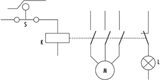
This channel uses switch S with positive action. The contactor K is supervised by the light L. The operator is advised that the normally open (NO) contacts stick by means of indication light L. The contactor K has forced guided contacts. (Note: Relays or contactors with forced guidance of contacts have, in comparison with usual relays or contactors, a special cage made from insulating material so that if normally closed (NC) contacts are closed, all NO contacts have to be opened, and vice versa. This means that by use of NC contacts a check may be made to determine that the working contacts are not sticking or welded together.)
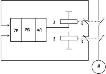
Category 2
Category 2 provides for automatic detection of failures. Automatic failure detection has to be generated before each dangerous movement. Only if the test is positive may the movement be performed; otherwise the machine will be stopped. Automatic failure detection systems are used for light barriers to prove that they are still working. The principle is illustrated in figure 1.
Figure 11. Circuit including a failure detector

This control system is tested regularly (or occasionally) by injecting an impulse to the input. In a properly working system this impulse will then be transferred to the output and compared to an impulse from a test generator. When both impulses are present, the system obviously works. Otherwise, if there is no output impulse, the system has failed.
Category 3
Circuitry has been previously described under Example 3 in the Safety section of this article, figure 8.
The requirement—that is, automatic failure detection and the ability to perform the safety function even if one failure has occurred anywhere—can be fulfilled by two-channel control structures and by mutual supervising of the two channels.
For machine controls only, the dangerous failures have to be investigated. It should be noted that there are two kinds of failure:
- Non-dangerous failures are those that, after their occurrence, cause a “safe state” of the machine by providing for switching off the motor.
- Dangerous failures are those that, after their occurrence, cause an “unsafe state” of the machine, as the motor cannot be switched off or the motor starts to move unexpectedly.
Category 4
Category 4 typically provides for the application of a dynamic, continuously changing signal on the input. The presence of a dynamic signal on the output means running (“1”), and the absence of a dynamic signal means stop (“0”).
For such circuitry it is typical that after failure of any component the dynamic signal will no longer be available on the output. (Note: The static potential on the output is irrelevant.) Such circuits may be called “fail-safe”. All failures will be disclosed immediately, not after the first change (as in Category 3 circuits).
Further comments on control categories
Table 1 has been developed for usual machine controls and shows the basic circuit structures only; according to the machine directive it should be calculated on the assumption that only one failure will occur in one machine cycle. This is why the safety function does not have to be performed in the case of two coincident failures. It is assumed that a failure will be detected within one machine cycle. The machine will be stopped and then repaired. The control system then starts again, fully operable, without failures.
The first intent of the designer should be not to permit “standing” failures, which would not be detected during one cycle as they might later be combined with newly occurring failure(s) (failure cumulation). Such combinations (a standing failure and a new failure) can cause a malfunction of even Category 3 circuitry.
In spite of these tactics, it is possible that two independent failures will occur at the same time within the same machine cycle. It is only very improbable, especially if highly reliable components have been used. For very high-risk applications, three or more subchannels should be used. This philosophy is based on the fact that the mean time between failures is much longer than the machine cycle.
This does not mean, however, that the table cannot be further expanded. Table 1 is basically and structurally very similar to the Table 2 used in EN 954-1. However, it does not try to include too many sorting criteria. The requirements are defined according to the rigorous laws of logic, so that only clear answers (YES or NO) can be expected. This allows a more exact assessment, sorting and classification of submitted circuitry (safety-related channels) and, last but not least, significant improvement of assessment reproducibility.
It would be ideal if risks could be classified in various risk levels and then a definite link established between risk levels and categories, with this all independent of the technology in use. However, this is not fully possible. Early after creating categories it became clear that even given the same technology, various questions were not sufficiently answered. Which is better: a very reliable and well-designed component of Category 1, or a system fulfilling the requirements of Category 3 with poor reliability?
To explain this dilemma one must differentiate between two qualities: reliability and safety (against failures). They are not comparable, as both these qualities have different features:
- The component with highest reliability has the unpleasant feature that in the event of failure (even if highly improbable) the function will cease to perform.
- Category 3 systems, where even in case of one failure the function will be performed, are not safe against two failures at the same time (what may be important is whether sufficiently reliable components have been used).
Considering the above, it may be that the best solution (from the high-risk point of view) is to use highly reliable components and configure them so that the circuitry is safe against at least one failure (preferably more). It is clear that such a solution is not the most economical. In practice, the optimization process is mostly the consequence of all these influences and considerations.
Experience with practical use of the categories shows that it is rarely possible to design a control system that can utilize only one category throughout. Combination of two or even three parts, each of a different category, is typical, as illustrated in the following example:
Many safety light barriers are designed in Category 4, wherein one channel works with a dynamic signal. At the end of this system there usually are two mutually supervised subchannels which work with static signals. (This fulfils the requirements for Category 3.)
According to EN 50100, such light barriers are classified as Type 4 electro-sensitive protective devices, although they are composed of two parts. Unfortunately, there is no agreement how to denominate control systems consisting of two or more parts, each part of another category.
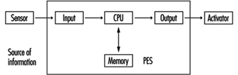
Programmable Electronic Systems (PESs)
The principles used to create table 1 can, with certain restrictions of course, be generally appled to PESs too.
PES-only system
In using PESs for control, the information is transferred from the sensor to the activator through a large number of components. Beyond that, it even passes “through” software. (See figure 12).
Figure 12. A PES system circuit
Although modern PESs are very reliable, the reliability is not as high as may be required for processing safety functions. Beyond that, the usual PES systems are not safe enough, since they will not perform the safety-related function in case of a failure. Therefore, using PESs for processing of safety functions without any additional measures is not permitted.
Very low-risk applications: Systems with one PES and additional measures
When using a single PES for control, the system consists of the following primary parts:
Input part
The reliability of a sensor and input of a PES can be improved by doubling them. Such a double-system input configuration can be further supervised by software to check if both subsystems are delivering the same information. Thus the failures in the input part can be detected. This is nearly the same philosophy as required for Category 3. However, because the supervising is done by software and only once, this may be denominated as 3- (or not as reliable as 3).
Middle part
Although this part cannot be well doubled, it can be tested. Upon switching on (or during operation), a check of the entire instruction set can be performed. At the same intervals, the memory can also be checked by suitable bit patterns. If such checks are conducted without failure, both parts, CPU and memory, are obviously working properly. The middle part has certain features typical of Category 4 (dynamic signal) and others typical of Category 2 (testing performed regularly at suitable intervals). The problem is that these tests, in spite of their extensiveness, cannot be really complete, as the one-PES system inherently does not allow them.
Output part
Similar to an input, the output (including activators) can also be doubled. Both subsystems can be supervised with respect to the same result. Failures will be detected and the safety function will be performed. However, there are the same weak points as in the input part. Consequently, Category 3 is chosen in this case.
In figure 13 the same function is brought to relays A and B. The control contacts a and b, then informs two input systems whether both relays are doing the same work (unless a failure in one of the channels has occurred). Supervising is done again by software.
Figure 13. A PES circuit with a failure-detection system
The whole system can be described as Category 3-/4/2/3- if properly and extensively done. Nevertheless, the weak points of such systems as above described cannot be fully eliminated. In fact, improved one PESs are actually used for safety-related functions only where the risks are rather low (Hölscher and Rader 1984).
Low- and medium-risk applications with one PES
Today almost every machine is equipped with a PES control unit. To solve the problem of insufficient reliability and usually insufficient safety against failure, the following design methods are commonly used:
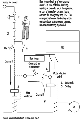
- In relatively simple machines such as lifts, the functions are divided into two groups: (1) the functions that are not related to safety are processed by the PES; (2) the safety-related functions are combined in one chain (safety circuit) and processed outside of the PES (see figure 14).
Figure 14. State of the art for stop category 0
- The method given above is not suitable for more complex machines. One reason is that such solutions usually are not safe enough. For medium-risk applications, solutions should fulfil the requirements for category 3. General ideas of how such designs may look are presented in figure 15 and figure 16.
Figure 15. State of the art for stop category 1

Figure 16. State of the art for stop category 2

High-risk applications: systems with two (or more) PESs
Aside from complexity and expense, there are no other factors that would prevent designers from using fully doubled PES systems such as Siemens Simatic S5-115F, 3B6 Typ CAR-MIL and so on. These typically include two identical PESs with homogenous software, and assume the use of “well-tried” PESs and “well-tried” compilers (a well-tried PES or compiler can be considered one that in many practical applications over 3 or more years has shown that systematic failures have been obviously eliminated). Although these doubled PES systems do not have the weak points of single-PES systems, it does not mean that doubled PES systems solve all problems. (See figure 17).
Figure 17. Sophisticated system with two PESs
Systematic Failures
Systematic failures may result from errors in specifications, design and other causes, and may be present in hardware as well as in software. Double-PES systems are suitable for use in safety-related applications. Such configurations allow the detection of random hardware failures. By means of hardware diversity such as the use of two different types, or products of two different manufacturers, systematic hardware failures could be disclosed (it is highly unlikely that an identical hardware systematic failure would occur in both PES).
Software
Software is a new element in safety considerations. Software is either correct or incorrect (with respect to failures). Once correct, software cannot become instantly incorrect (as compared to hardware). The aims are to eradicate all errors in the software or to at least identify them.
There are various ways of achieving this goal. One is the verification of the program (a second person attempts to discover the errors in a subsequent test). Another possibility is diversity of the software, wherein two different programs, written by two programmers, address the same problem. If the results are identical (within certain limits), it can be assumed that both program sections are correct. If the results are different, it is presumed that errors are present. (N.B., The architecture of the hardware naturally must also be considered.)
Summary
When using PESs, generally the same following basic considerations are to be taken in account (as described in the previous sections).
- One control system without any redundancy may be allocated to Category B. One control system with additional measures may be Category 1 or even higher, but not higher than 2.
- A two-part control system with mutual comparison of results may be allocated to Category 3. A two-part control system with mutual comparison of results and more or less diversity may be allocated to Category 3 and is suitable for higher-risk applications.
A new factor is that for the system with a PES, even software should be evaluated from the correctness point of view. Software, if correct, is 100% reliable. At this stage of technological development, the best possible and known technical solutions will probably not be used, since the limiting factors are still economic. Furthermore, various groups of experts are continuing to develop the standards for safety applications of PESs (e.g., EC, EWICS). Although there are various standards already available (VDE0801, IEC65A and so on), this matter is so broad and complex that none of them may be considered as final.