- You are here:
-
Home

-
k2 Feed
-
Psychological Aspects
- Mental Workload
Software and Computers: Hybrid Automated Systems
A hybrid automated system (HAS) aims to integrate the capabilities of artificially intelligent machines (based on computer technology) with the capacities of the people who interact with these machines in the course of their work activities. The principal concerns of HAS utilization relate to how the human and machine subsystems should be designed in order to make the best use of the knowledge and skills of both parts of the hybrid system, and how the human operators and machine components should interact with each other to assure their functions complement one another. Many hybrid automated systems have evolved as the products of applications of modern information- and control-based methodologies to automate and integrate different functions of often complex technological systems. HAS was originally identified with the introduction of computer-based systems used in the design and operation of real-time control systems for nuclear power reactors, for chemical processing plants and for discrete parts-manufacturing technology. HAS can now also be found in many service industries, such as air traffic control and aircraft navigation procedures in the civil aviation area, and in the design and use of intelligent vehicle and highway navigation systems in road transportation.
With continuing progress in computer-based automation, the nature of human tasks in modern technological systems shifts from those that require perceptual-motor skills to those calling for cognitive activities, which are needed for problem solving, for decision making in system monitoring, and for supervisory control tasks. For example, the human operators in computer-integrated manufacturing systems primarily act as system monitors, problem solvers and decision makers. The cognitive activities of the human supervisor in any HAS environment are (1) planning what should be done for a given period of time, (2) devising procedures (or steps) to achieve the set of planned goals, (3) monitoring the progress of (technological) processes, (4) “teaching” the system through a human-interactive computer, (5) intervening if the system behaves abnormally or if the control priorities change and (6) learning through feedback from the system about the impact of supervisory actions (Sheridan 1987).
Hybrid System Design
The human-machine interactions in a HAS involve utilization of dynamic communication loops between the human operators and intelligent machines—a process that includes information sensing and processing and the initiation and execution of control tasks and decision making—within a given structure of function allocation between humans and machines. At a minimum, the interactions between people and automation should reflect the high complexity of hybrid automated systems, as well as relevant characteristics of the human operators and task requirements. Therefore, the hybrid automated system can be formally defined as a quintuple in the following formula:
HAS = (T, U, C, E, I)
where T = task requirements (physical and cognitive); U = user characteristics (physical and cognitive); C = the automation characteristics (hardware and software, including computer interfaces); E = the system’s environment; I = a set of interactions among the above elements.
The set of interactions I embodies all possible interactions between T, U and C in E regardless of their nature or strength of association. For example, one of the possible interactions might involve the relation of the data stored in the computer memory to the corresponding knowledge, if any, of the human operator. The interactions I can be elemental (i.e., limited to a one-to-one association), or complex, such as would involve interactions between the human operator, the particular software used to achieve the desired task, and the available physical interface with the computer.
Designers of many hybrid automated systems focus primarily on the computer-aided integration of sophisticated machines and other equipment as parts of computer-based technology, rarely paying much attention to the paramount need for effective human integration within such systems. Therefore, at present, many of the computer-integrated (technological) systems are not fully compatible with the inherent capabilities of the human operators as expressed by the skills and knowledge necessary for the effective control and monitoring of these systems. Such incompatibility arises at all levels of human, machine and human-machine functioning, and can be defined within a framework of the individual and the entire organization or facility. For example, the problems of integrating people and technology in advanced manufacturing enterprises occur early in the HAS design stage. These problems can be conceptualized using the following system integration model of the complexity of interactions, I, between the system designers, D, human operators, H, or potential system users and technology, T:
I (H, T) = F [ I (H, D), I (D, T)]
where I stands for relevant interactions taking place in a given HAS’s structure, while F indicates functional relationships between designers, human operators and technology.
The above system integration model highlights the fact that the interactions between the users and technology are determined by the outcome of the integration of the two earlier interactions—namely, (1) those between HAS designers and potential users and (2) those between the designers and the HAS technology (at the level of machines and their integration). It should be noted that even though strong interactions typically exist between the designers and technology, only very few examples of equally strong interrelationships between designers and human operators can be found.
It can be argued that even in the most automated systems, the human role remains critical to successful system performance at the operational level. Bainbridge (1983) identified a set of problems relevant to the operation of the HAS which are due to the nature of automation itself, as follows:
- Operators “out of the control loop”. The human operators are present in the system to exercise control when needed, but by being “out of the control loop” they fail to maintain the manual skills and long-term system knowledge that are often required in case of an emergency.
- Outdated “mental picture”. The human operators may not be able to respond quickly to changes in the system behaviour if they have not been following the events of its operation very closely. Furthermore, the operators’ knowledge or mental picture of the system functioning may be inadequate to initiate or exercise required responses.
- Disappearing generations of skills. New operators may not be able to acquire sufficient knowledge about the computerized system achieved through experience and, therefore, will be unable to exercise effective control when needed.
- Authority of automatics. If the computerized system has been implemented because it can perform the required tasks better than the human operator, the question arises, “On what basis should the operator decide that correct or incorrect decisions are being made by the automated systems?”
- Emergence of the new types of “human errors” due to automation. Automated systems lead to new types of errors and, consequently, accidents which cannot be analysed within the framework of traditional techniques of analysis.
Task Allocation
One of the important issues for HAS design is to determine how many and which functions or responsibilities should be allocated to the human operators, and which and how many to the computers. Generally, there are three basic classes of task allocation problems that should be considered: (1) the human supervisor–computer task allocation, (2) the human–human task allocation and (3) the supervisory computer–computer task allocation. Ideally, the allocation decisions should be made through some structured allocation procedure before the basic system design is begun. Unfortunately such a systematic process is seldom possible, as the functions to be allocated may either need further examination or must be carried out interactively between the human and machine system components—that is, through application of the supervisory control paradigm. Task allocation in hybrid automated systems should focus on the extent of the human and computer supervisory responsibilities, and should consider the nature of interactions between the human operator and computerized decision support systems. The means of information transfer between machines and the human input-output interfaces and the compatibility of software with human cognitive problem-solving abilities should also be considered.
In traditional approaches to the design and management of hybrid automated systems, workers were considered as deterministic input-output systems, and there was a tendency to disregard the teleological nature of human behaviour—that is, the goal-oriented behaviour relying on the acquisition of relevant information and the selection of goals (Goodstein et al. 1988). To be successful, the design and management of advanced hybrid automated systems must be based on a description of the human mental functions needed for a specific task. The “cognitive engineering” approach (described further below) proposes that human-machine (hybrid) systems need to be conceived, designed, analysed and evaluated in terms of human mental processes (i.e., the operator’s mental model of the adaptive systems is taken into account). The following are the requirements of the human-centred approach to HAS design and operation as formulated by Corbett (1988):
- Compatibility. System operation should not require skills unrelated to existing skills, but should allow existing skills to evolve. The human operator should input and receive information which is compatible with conventional practice in order that the interface conform to the user’s prior knowledge and skill.
- Transparency. One cannot control a system without understanding it. Therefore, the human operator must be able to “see” the internal processes of the system’s control software if learning is to be facilitated. A transparent system makes it easy for users to build up an internal model of the decision-making and control functions that the system can perform.
- Minimum shock. The system should not do anything which operators find unexpected in the light of the information available to them, detailing the present state of the system.
- Disturbance control. Uncertain tasks (as defined by the choice structure analysis) should be under human operator control with computer decision-making support.
- Fallibility. The implicit skills and knowledge of the human operators should not be designed out of the system. The operators should never be put in a position where they helplessly watch the software direct an incorrect operation.
- Error reversibility. Software should supply sufficient feedforward of information to inform the human operator of the likely consequences of a particular operation or strategy.
- Operating flexibility. The system should offer human operators the freedom to trade off requirements and resource limits by shifting operating strategies without losing the control software support.
Cognitive Human Factors Engineering
Cognitive human factors engineering focuses on how human operators make decisions at the workplace, solve problems, formulate plans and learn new skills (Hollnagel and Woods 1983). The roles of the human operators functioning in any HAS can be classified using Rasmussen’s scheme (1983) into three major categories:
- Skill-based behaviour is the sensory-motor performance executed during acts or activities which take place without conscious control as smooth, automated and highly integrated patterns of behaviour. Human activities that fall under this category are considered to be a sequence of skilled acts composed for a given situation. Skill-based behaviour is thus the expression of more or less stored patterns of behaviours or pre-programmed instructions in a space-time domain.
- Rule-based behaviour is a goal-oriented category of performance structured by feedforward control through a stored rule or procedure—that is, an ordered performance allowing a sequence of subroutines in a familiar work situation to be composed. The rule is typically selected from previous experiences and reflects the functional properties which constrain the behaviour of the environment. Rule-based performance is based on explicit know-how as regards employing the relevant rules. The decision data set consists of references for recognition and identification of states, events or situations.
- Knowledge-based behaviour is a category of goal-controlled performance, in which the goal is explicitly formulated based on knowledge of the environment and the aims of the person. The internal structure of the system is represented by a “mental model”. This kind of behaviour allows the development and testing of different plans under unfamiliar and, therefore, uncertain control conditions, and is needed when skills or rules are either unavailable or inadequate so that problem solving and planning must be called upon instead.
In the design and management of a HAS, one should consider the cognitive characteristics of the workers in order to assure the compatibility of system operation with the worker’s internal model that describes its functions. Consequently, the system’s description level should be shifted from the skill-based to the rule-based and knowledge-based aspects of human functioning, and appropriate methods of cognitive task analysis should be used to identify the operator’s model of a system. A related issue in the development of a HAS is the design of means of information transmission between the human operator and automated system components, at both the physical and the cognitive levels. Such information transfer should be compatible with the modes of information utilized at different levels of system operation—that is, visual, verbal, tactile or hybrid. This informational compatibility ensures that different forms of information transfer will require minimal incompatibility between the medium and the nature of the information. For example, a visual display is best for transmission of spatial information, while auditory input may be used to convey textual information.
Quite often the human operator develops an internal model that describes the operation and function of the system according to his or her experience, training and instructions in connection with the given type of human-machine interface. In light of this reality, the designers of a HAS should attempt to build into the machines (or other artificial systems) a model of the human operator’s physical and cognitive characteristics—that is, the system’s image of the operator (Hollnagel and Woods 1983). The designers of a HAS must also take into consideration the level of abstraction in the system description as well as various relevant categories of the human operator’s behaviour. These levels of abstraction for modelling human functioning in the working environment are as follows (Rasmussen 1983): (1) physical form (anatomical structure), (2) physical functions (physiological functions), (3) generalized functions (psychological mechanisms and cognitive and affective processes), (4) abstract functions (information processing) and (5) functional purpose (value structures, myths, religions, human interactions). These five levels must be considered simultaneously by the designers in order to ensure effective HAS performance.
System Software Design
Since the computer software is a primary component of any HAS environment, software development, including design, testing, operation and modification, and software reliability issues must also be considered at the early stages of HAS development. By this means, one should be able to lower the cost of software error detection and elimination. It is difficult, however, to estimate the reliability of the human components of a HAS, on account of limitations in our ability to model human task performance, the related workload and potential errors. Excessive or insufficient mental workload may lead to information overload and boredom, respectively, and may result in degraded human performance, leading to errors and the increasing probability of accidents. The designers of a HAS should employ adaptive interfaces, which utilize artificial intelligence techniques, to solve these problems. In addition to human-machine compatibility, the issue of human-machine adaptability to each other must be considered in order to reduce the stress levels that come about when human capabilities may be exceeded.
Due to the high level of complexity of many hybrid automated systems, identification of any potential hazards related to the hardware, software, operational procedures and human-machine interactions of these systems becomes critical to the success of efforts aimed at reduction of injuries and equipment damage. Safety and health hazards associated with complex hybrid automated systems, such as computer-integrated manufacturing technology (CIM), is clearly one of the most critical aspects of system design and operation.
System Safety Issues
Hybrid automated environments, with their significant potential for erratic behaviour of the control software under system disturbance conditions, create a new generation of accident risks. As hybrid automated systems become more versatile and complex, system disturbances, including start-up and shut-down problems and deviations in system control, can significantly increase the possibility of serious danger to the human operators. Ironically, in many abnormal situations, operators usually rely on the proper functioning of the automated safety subsystems, a practice which may increase the risk of severe injury. For example, a study of accidents related to malfunctions of technical control systems showed that about one-third of the accident sequences included human intervention in the control loop of the disturbed system.
Since traditional safety measures cannot be easily adapted to the needs of HAS environments, injury control and accident prevention strategies need to be reconsidered in view of the inherent characteristics of these systems. For example, in the area of advanced manufacturing technology, many processes are characterized by the existence of substantial amounts of energy flows which cannot be easily anticipated by the human operators. Furthermore, safety problems typically emerge at the interfaces between subsystems, or when system disturbances progress from one subsystem to another. According to the International Organization for Standardization (ISO 1991), the risks associated with hazards due to industrial automation vary with the types of industrial machines incorporated into the specific manufacturing system and with the ways in which the system is installed, programmed, operated, maintained and repaired. For example, a comparison of robot-related accidents in Sweden to other types of accidents showed that robots may be the most hazardous industrial machines used in advanced manufacturing industry. The estimated accident rate for industrial robots was one serious accident per 45 robot-years, a higher rate than that for industrial presses, which was reported to be one accident per 50 machine-years. It should be noted here that industrial presses in the United States accounted for about 23% of all metalworking machine-related fatalities for the 1980–1985 period, with power presses ranked first with respect to the severity-frequency product for non-fatal injuries.
In the domain of advanced manufacturing technology, there are many moving parts which are hazardous to workers as they change their position in a complex manner outside the visual field of the human operators. Rapid technological developments in computer-integrated manufacturing created a critical need to study the effects of advanced manufacturing technology on the workers. In order to identify the hazards caused by various components of such a HAS environment, past accidents need to be carefully analysed. Unfortunately, accidents involving robot use are difficult to isolate from reports of human operated machine-related accidents, and, therefore, there may be a high percentage of unrecorded accidents. The occupational health and safety rules of Japan state that “industrial robots do not at present have reliable means of safety and workers cannot be protected from them unless their use is regulated”. For example, the results of the survey conducted by the Labour Ministry of Japan (Sugimoto 1987) of accidents related to industrial robots across the 190 factories surveyed (with 4,341 working robots) showed that there were 300 robot-related disturbances, of which 37 cases of unsafe acts resulted in some near accidents, 9 were injury-producing accidents, and 2 were fatal accidents. The results of other studies indicate that computer-based automation does not necessarily increase the overall level of safety, as the system hardware cannot be made fail-safe by safety functions in the computer software alone, and system controllers are not always highly reliable. Furthermore, in a complex HAS, one cannot depend exclusively on safety-sensing devices to detect hazardous conditions and undertake appropriate hazard-avoidance strategies.
Effects of Automation on Human Health
As discussed above, worker activities in many HAS environments are basically those of supervisory control, monitoring, system support and maintenance. These activities may also be classified into four basic groups as follows: (1) programming tasks i.e., encoding the information that guides and directs machinery operation, (2) monitoring of HAS production and control components, (3) maintenance of HAS components to prevent or alleviate machinery malfunctions, and (4) performing a variety of support tasks, etc. Many recent reviews of the impact of the HAS on worker well-being concluded that although the utilization of a HAS in the manufacturing area may eliminate heavy and dangerous tasks, working in a HAS environment may be dissatisfying and stressful for the workers. Sources of stress included the constant monitoring required in many HAS applications, the limited scope of the allocated activities, the low level of worker interaction permitted by the system design, and safety hazards associated with the unpredictable and uncontrollable nature of the equipment. Even though some workers who are involved in programming and maintenance activities feel the elements of challenge, which may have positive effects on their well-being, these effects are often offset by the complex and demanding nature of these activities, as well as by the pressure exerted by management to complete these activities quickly.
Although in some HAS environments the human operators are removed from traditional energy sources (the flow of work and movement of the machine) during normal operating conditions, many tasks in automated systems still need to be carried out in direct contact with other energy sources. Since the number of different HAS components is continually increasing, special emphasis must be placed on workers’ comfort and safety and on the development of effective injury control provisions, especially in view of the fact that the workers are no longer able to keep up with the sophistication and complexity of such systems.
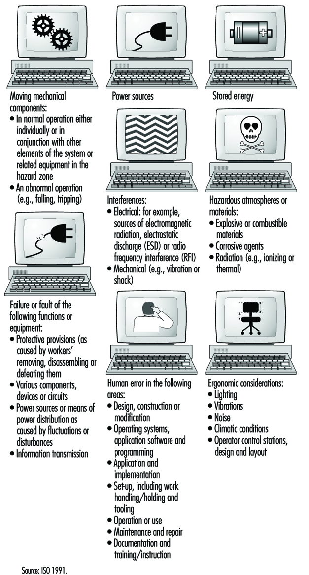
In order to meet the current needs for injury control and worker safety in computer integrated manufacturing systems, the ISO Committee on Industrial Automation Systems has proposed a new safety standard entitled “Safety of Integrated Manufacturing Systems” (1991). This new international standard, which was developed in recognition of the particular hazards which exist in integrated manufacturing systems incorporating industrial machines and associated equipment, aims to minimize the possibilities of injuries to personnel while working on or adjacent to an integrated manufacturing system. The main sources of potential hazards to the human operators in CIM identified by this standard are shown in figure 1.
Figure 1. Main source of hazards in computer-intergrated manufacturing (CIM) (after ISO 1991)
Human and System Errors
In general, hazards in a HAS can arise from the system itself, from its association with other equipment present in the physical environment, or from interactions of human personnel with the system. An accident is only one of the several outcomes of human-machine interactions that may emerge under hazardous conditions; near accidents and damage incidents are much more common (Zimolong and Duda 1992). The occurrence of an error can lead to one of these consequences: (1) the error remains unnoticed, (2) the system can compensate for the error, (3) the error leads to a machine breakdown and/or system stoppage or (4) the error leads to an accident.
Since not every human error that results in a critical incident will cause an actual accident, it is appropriate to distinguish further among outcome categories as follows: (1) an unsafe incident (i.e., any unintentional occurrence regardless whether it results in injury, damage or loss), (2) an accident (i.e., an unsafe event resulting in injury, damage or loss), (3) a damage incident (i.e., an unsafe event which results only in some kind of material damage), (4) a near accident or “near miss” (i.e., an unsafe event in which injury, damage or loss was fortuitously avoided by a narrow margin) and (5) the existence of accident potential (i.e., unsafe events which could have resulted in injury, damage, or loss, but, owing to circumstances, did not result in even a near accident).
One can distinguish three basic types of human error in a HAS:
- skill-based slips and lapses
- rule-based mistakes
- knowledge-based mistakes.
This taxonomy, devised by Reason (1990), is based on a modification of Rasmussen’s skill-rule-knowledge classification of human performance as described above. At the skill-based level, human performance is governed by stored patterns of pre-programmed instructions represented as analogue structures in a space-time domain. The rule-based level is applicable to tackling familiar problems in which solutions are governed by stored rules (called “productions”, since they are accessed, or produced, at need). These rules require certain diagnoses (or judgements) to be made, or certain remedial actions to be taken, given that certain conditions have arisen that demand an appropriate response. At this level, human errors are typically associated with the misclassification of situations, leading either to the application of the wrong rule or to the incorrect recall of consequent judgements or procedures. Knowledge-based errors occur in novel situations for which actions must be planned “on-line” (at a given moment), using conscious analytical processes and stored knowledge. Errors at this level arise from resource limitations and incomplete or incorrect knowledge.
The generic error-modelling systems (GEMS) proposed by Reason (1990), which attempts to locate the origins of the basic human error types, can be used to derive the overall taxonomy of human behaviour in a HAS. GEMS seeks to integrate two distinct areas of error research: (1) slips and lapses, in which actions deviate from current intention due to execution failures and/or storage failures and (2) mistakes, in which the actions may run according to plan, but the plan is inadequate to achieve its desired outcome.
Risk Assessment and Prevention in CIM
According to the ISO (1991), risk assessment in CIM should be performed so as to minimize all risks and to serve as a basis for determining safety objectives and measures in the development of programmes or plans both to create a safe working environment and to ensure the safety and health of personnel as well. For example, work hazards in manufacturing-based HAS environments can be characterized as follows: (1) the human operator may need to enter the danger zone during disturbance recovery, service and maintenance tasks, (2) the danger zone is difficult to determine, to perceive and to control, (3) the work may be monotonous and (4) the accidents occurring within computer-integrated manufacturing systems are often serious. Each identified hazard should be assessed for its risk, and appropriate safety measures should be determined and implemented to minimize that risk. Hazards should also be ascertained with respect to all of the following aspects of any given process: the single unit itself; the interaction between single units; the operating sections of the system; and the operation of the complete system for all intended operating modes and conditions, including conditions under which normal safeguarding means are suspended for such operations as programming, verification, troubleshooting, maintenance or repair.
The design phase of the ISO (1991) safety strategy for CIM includes:
- specification of the limits of system parameters
- application of a safety strategy
- identification of hazards
- assessment of the associated risks
- removal of the hazards or diminution of the risks as much as practicable.
The system safety specification should include:
- a description of system functions
- a system layout and/or model
- the results of a survey undertaken to investigate the interaction of different working processes and manual activities
- an analysis of process sequences, including manual interaction
- a description of the interfaces with conveyor or transport lines
- process flow charts
- foundation plans
- plans for supply and disposal devices
- determination of the space required for supply and disposal of material
- available accident records.
In accordance with the ISO (1991), all necessary requirements for ensuring a safe CIM system operation need to be considered in the design of systematic safety-planning procedures. This includes all protective measures to effectively reduce hazards and requires:
- integration of the human-machine interface
- early definition of the position of those working on the system (in time and space)
- early consideration of ways of cutting down on isolated work
- consideration of environmental aspects.
The safety planning procedure should address, among others, the following safety issues of CIM:
- Selection of the operating modes of the system. The control equipment should have provisions for at least the following operating modes:(1) normal or production mode (i.e., with all normal safeguards connected and operating), (2) operation with some of the normal safeguards suspended and (3) operation in which system or remote manual initiation of hazardous situations is prevented (e.g., in the case of local operation or of isolation of power to or mechanical blockage of hazardous conditions).
- Training, installation, commissioning and functional testing. When personnel are required to be in the hazard zone, the following safety measures should be provided in the control system: (1) hold to run, (2) enabling device, (3) reduced speed, (4) reduced power and (5) moveable emergency stop.
- Safety in system programming, maintenance and repair. During programming, only the programmer should be allowed in the safeguarded space. The system should have inspection and maintenance procedures in place to ensure continued intended operation of the system. The inspection and maintenance programme should take into account the recommendations of the system supplier and those of suppliers of various elements of the systems. It scarcely needs mentioning that personnel who perform maintenance or repairs on the system should be trained in the procedures necessary to perform the required tasks.
- Fault elimination. Where fault elimination is necessary from inside the safeguarded space, it should be performed after safe disconnection (or, if possible, after a lockout mechanism has been actuated). Additional measures against erroneous initiation of hazardous situations should be taken. Where hazards can occur during fault elimination at sections of the system or at the machines of adjoining systems or machines, these should also be taken out of operation and protected against unexpected starting. By means of instruction and warning signs, attention should be drawn to fault elimination in system components which cannot be observed completely.
System Disturbance Control
In many HAS installations utilized in the computer-integrated manufacturing area, human operators are typically needed for the purpose of controlling, programming, maintaining, pre-setting, servicing or troubleshooting tasks. Disturbances in the system lead to situations that make it necessary for workers to enter the hazardous areas. In this respect, it can be assumed that disturbances remain the most important reason for human interference in CIM, because the systems will more often than not be programmed from outside the restricted areas. One of the most important issues for CIM safety is to prevent disturbances, since most risks occur in the troubleshooting phase of the system. The avoidance of disturbances is the common aim as regards both safety and cost-effectiveness.
A disturbance in a CIM system is a state or function of a system that deviates from the planned or desired state. In addition to productivity, disturbances during the operation of a CIM have a direct effect on the safety of the people involved in operating the system. A Finnish study (Kuivanen 1990) showed that about one-half of the disturbances in automated manufacturing decrease the safety of the workers. The main causes for disturbances were errors in system design (34%), system component failures (31%), human error (20%) and external factors (15%). Most machine failures were caused by the control system, and, in the control system, most failures occurred in sensors. An effective way to increase the level of safety of CIM installations is to reduce the number of disturbances. Although human actions in disturbed systems prevent the occurrence of accidents in the HAS environment, they also contribute to them. For example, a study of accidents related to malfunctions of technical control systems showed that about one-third of the accident sequences included human intervention in the control loop of the disturbed system.
The main research issues in CIM disturbance prevention concern (1) major causes of disturbances, (2) unreliable components and functions, (3) the impact of disturbances on safety, (4) the impact of disturbances on the function of the system, (5) material damage and (6) repairs. The safety of HAS should be planned early at the system design stage, with due consideration of technology, people and organization, and be an integral part of the overall HAS technical planning process.
HAS Design: Future Challenges
To assure the fullest benefit of hybrid automated systems as discussed above, a much broader vision of system development, one which is based on integration of people, organization and technology, is needed. Three main types of system integration should be applied here:
- integration of people, by assuring effective communication between them
- human-computer integration, by designing suitable interfaces and interaction between people and computers
- technological integration, by assuring effective interfacing and interactions between machines.
The minimum design requirements for hybrid automated systems should include the following: (1) flexibility, (2) dynamic adaptation, (3) improved responsiveness, and (4) the need to motivate people and make better use of their skills, judgement and experience. The above also requires that HAS organizational structures, work practices and technologies be developed to allow people at all levels of the system to adapt their work strategies to the variety of systems control situations. Therefore, the organizations, work practices and technologies of HAS will have to be designed and developed as open systems (Kidd 1994).
An open hybrid automated system (OHAS) is a system that receives inputs from and sends outputs to its environment. The idea of an open system can be applied not only to system architectures and organizational structures, but also to work practices, human-computer interfaces, and the relationship between people and technologies: one may mention, for example, scheduling systems, control systems and decision support systems. An open system is also an adaptive one when it allows people a large degree of freedom to define the mode of operating the system. For example, in the area of advanced manufacturing, the requirements of an open hybrid automated system can be realized through the concept of human and computer-integrated manufacturing (HCIM). In this view, the design of technology should address the overall HCIM system architecture, including the following: (1) considerations of the network of groups, (2) the structure of each group, (3) the interaction between groups, (4) the nature of the supporting software and (5) technical communication and integration needs between supporting software modules.
The adaptive hybrid automated system, as opposed to the closed system, does not restrict what the human operators can do. The role of the designer of a HAS is to create a system that will satisfy the user’s personal preferences and allow its users to work in a way that they find most appropriate. A prerequisite for permitting user input is the development of an adaptive design methodology—that is, an OHAS that allows enabling, computer-supported technology for its implementation in the design process. The need to develop a methodology for adaptive design is one of the immediate requirements to realize the OHAS concept in practice. A new level of adaptive human supervisory control technology needs also to be developed. Such technology should allow the human operator to “see through” the otherwise invisible control system of HAS functioning—for example, by application of an interactive, high-speed video system at each point of system control and operation. Finally, a methodology for development of an intelligent and highly adaptive, computer-based support of human roles and human functioning in the hybrid automated systems is also very much needed.
Safety-Related Applications
In the last few years microprocessors have played an ever-increasing role in the field of safety technology. Because entire computers (i.e., central processing unit, memory and peripheral components) are now available in a single component as “single-chip computers”, microprocessor technology is being employed not only in complex machine control, but also in safeguards of relatively simple design (e.g., light grids, two-hand control devices and safety edges). The software controlling these systems comprises between one thousand and several tens of thousands of single commands and usually consists of several hundred program branches. The programs operate in real time and are mostly written in the programmers’ assembly language.
The introduction of computer-controlled systems in the sphere of safety technology has been accompanied in all large-scale technical equipment not only by expensive research and development projects but also by significant restrictions designed to enhance safety. (Aerospace technology, military technology and atomic power technology may here be cited as examples of large-scale applications.) The collective field of industrial mass production has up to now been treated only in a very limited fashion. This is partly for the reason that the rapid cycles of innovation characteristic of industrial machine design make it difficult to carry over, in any but a very restricted manner, such knowledge as may be derived from research projects concerned with the final testing of large-scale safety devices. This makes the development of rapid and low-cost assessment procedures a desideratum (Reinert and Reuss 1991).
This article first examines machines and facilities in which computer systems presently perform safety tasks, using examples of accidents occurring preponderantly in the area of machine safeguards to depict the particular role which computers play in safety technology. These accidents give some indication as to which precautions must be taken so that the computer-controlled safety equipment currently coming into increasingly wide use will not lead to a rise in the number of accidents. The final section of the article sketches out a procedure which will enable even small computer systems to be brought to an appropriate level of technical safety at justifiable expense and within an acceptable period of time. The principles indicated in this final part are currently being introduced into international standardization procedures and will have implications for all areas of safety technology in which computers find application.
Examples of the Use of Software and Computers in the Field of Machine Safeguards
The following four examples make it clear that software and computers are currently entering more and more into safety-related applications in the commercial domain.
Personal-emergency signal installations consist, as a rule, of a central receiving station and a number of personal emergency signalling devices. The devices are carried by persons working onsite by themselves. If any of these persons working alone find themselves in an emergency situation, they can use the device to trip an alarm by radio signal in the central receiving station. Such a will-dependent alarm trigger may also be supplemented by a will-independent triggering mechanism activated by sensors built into the personal emergency devices. Both the individual devices and the central receiving station are frequently controlled by microcomputers. It is conceivable that failure of specific single functions of the built-in computer could lead, in an emergency situation, to a failure to trip the alarm. Precautions must therefore be taken to perceive and to repair such loss of function in time.
Printing presses used today to print magazines are large machines. The paper webs are normally prepared by a separate machine in such a way as to enable a seamless transition to a new paper roll. The printed pages are folded by a folding machine and subsequently worked through a chain of further machines. This results in pallets loaded with fully sewn magazines. Although such plants are automated, there are two points at which manual interventions must be made: (1) in the threading of the paper paths, and (2) in clearing obstructions caused by paper tears at danger spots on the rotating rollers. For this reason, a reduced speed of operation or a path- or time-limited jogging mode must be ensured by the control technology while the presses are being adjusted. On account of the complex steering procedures involved, every single printing station must be equipped with its own programmable logic controller. Any failure occurring in the control of a printing plant while guard grids are open must be kept from leading either to the unexpected start-up of a stopped machine or to operation in excess of appropriately reduced speeds.
In large factories and warehouses, driverless, automated guided robot vehicles move about on specially marked tracks. These tracks can be walked upon at any time by persons, or materials and equipment may be inadvertently left on the tracks, since they are not separated structurally from other lines of traffic. For this reason, some sort of collision-prevention equipment must be used to ensure that the vehicle will be brought to a halt before any dangerous collision with a person or object occurs. In more recent applications, collision prevention is effected by means of ultrasonic or laser light scanners used in combination with a safety bumper. Since these systems work under computer control, it is possible to configure several permanent detection zones so that a vehicle can modify its reaction depending on the specific detection zone in which a person is located. Failures in the protective device must not lead to a dangerous collision with a person.
Paper-cutting control device guillotines are used to press and then cut thick stacks of paper. They are triggered by a two-hand control device. The user must reach into the danger zone of the machine after each cut is made. An immaterial safeguard, usually a light grid, is used in conjunction with both the two-hand control device and a safe machine-control system to prevent injuries when paper is fed during the cutting operation. Nearly all the larger, more modern guillotines in use today are controlled by multichannel microcomputer systems. Both the two-hand operation and the light grid must also be guaranteed to function safely.
Accidents with Computer-Controlled Systems
In nearly all fields of industrial application, accidents with software and computers are reported (Neumann 1994). In most cases, computer failures do not lead to injury to persons. Such failures are in any case made public only when they are of general public interest. This means that the instances of malfunction or accident related to computers and software in which injury to persons is involved make up a relatively high proportion of all publicized cases. Unfortunately, accidents which do not cause much of a public sensation are not investigated as to their causes with quite the same intensity as are more prominent accidents, typically in large-scale plants. For this reason, the examples which follow refer to four descriptions of malfunctions or accidents typical of computer-controlled systems outside the field of machine safeguards, which are used to suggest what has to be taken into account when judgements concerning safety technology are made.
Accidents caused by random failures in hardware
The following mishap was caused by a concentration of random failures in the hardware combined with programming failure: A reactor overheated in a chemical plant, whereupon relief valves were opened, allowing the contents of the reactor to be discharged into the atmosphere. This mishap occurred a short time after a warning had been given that the oil level in a gearbox was too low. Careful investigation of the mishap showed that shortly after the catalyst had initiated the reaction in the reactor—in consequence of which the reactor would have required more cooling—the computer, on the basis of the report of low oil levels in the gearbox, froze all magnitudes under its control at a fixed value. This kept the cold water flow at too low a level and the reactor overheated as a result. Further investigation showed that the indication of low oil levels had been signalled by a faulty component.
The software had responded according to the specification with the tripping of an alarm and the fixing of all operative variables. This was a consequence of the HAZOP (hazards and operability analysis) study (Knowlton 1986) done prior to the event, which required that all controlled variables not be modified in the event of a failure. Since the programmer was not acquainted with the procedure in detail, this requirement was interpreted to mean that the controlled actuators (control valves in this case) were not to be modified; no attention was paid to the possibility of a rise in temperature. The programmer did not take into consideration that after having received an erroneous signal the system might find itself in a dynamic situation of a type requiring the active intervention of the computer to prevent a mishap. The situation which led to the mishap was so unlikely, moreover, that it had not been analysed in detail in the HAZOP study (Levenson 1986). This example provides a transition to a second category of causes of software and computer accidents. These are the systematic failures which are in the system from the beginning, but which manifest themselves only in certain very specific situations which the developer has not taken into account.
Accidents caused by operating failures
In field testing during the final inspection of robots, one technician borrowed the cassette of a neighbouring robot and substituted a different one without informing his colleague that he had done so. Upon returning to his workplace, the colleague inserted the wrong cassette. Since he stood next to the robot and expected a particular sequence of movements from it—a sequence which came out differently on account of the exchanged program—a collision occurred between robot and human. This accident describes the classical example of an operating failure. The role of such failures in malfunctions and accidents is currently increasing due to increasing complexity in the application of computer-controlled safety mechanisms.
Accidents caused by systematic failures in hardware or software
A torpedo with a warhead was to have been fired for training purposes, from a warship on the high seas. On account of a defect in the drive apparatus the torpedo remained in the torpedo tube. The captain decided to return to the home port in order to salvage the torpedo. Shortly after the ship had begun to make its way back home, the torpedo exploded. An analysis of the accident revealed that the torpedo’s developers had been obliged to build into the torpedo a mechanism designed to prevent its returning to the launching pad after having been fired and thus destroying the ship that had launched it. The mechanism chosen for this was as follows: After the firing of the torpedo a check was made, using the inertial navigation system, to see whether its course had altered by 180°. As soon as the torpedo sensed that it had turned 180°, the torpedo detonated immediately, supposedly at a safe distance from the launching pad. This detection mechanism was actuated in the case of the torpedo which had not been properly launched, with the result that the torpedo exploded after the ship had changed its course by 180°. This is a typical example of an accident occurring on account of a failure in specifications. The requirement in the specifications that the torpedo should not destroy its own ship should its course change was not formulated precisely enough; the precaution was thus programmed erroneously. The error became apparent only in a particular situation, one which the programmer had not taken into account as a possibility.
On 14 September 1993, a Lufthansa Airbus A 320 crashed while landing in Warsaw (figure 1). A careful investigation of the accident showed that modifications in the landing logic of the on-board computer made after an accident with a Lauda Air Boeing 767 in 1991 were partly responsible for this crash landing. What had happened in the 1991 accident was that the thrust deflection, which diverts some part of the motor gases so as to brake the airplane during landing, had engaged while still in the air, thus forcing the machine into an uncontrollable nose-dive. For this reason, an electronic locking of the thrust deflection had been built into the Airbus machines. This mechanism permitted thrust deflection to come into effect only after sensors on both sets of landing gear had signalled the compression of the shock absorbers under the pressure of the wheels touching down. On the basis of incorrect information, the pilots of the plane in Warsaw anticipated a strong side wind.
Figure 1. Lufthansa Airbus after accident in Warsaw 1993
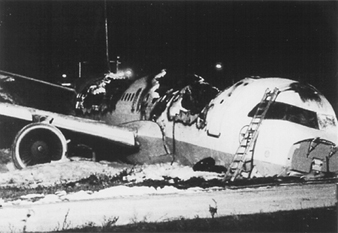
For this reason they brought the machine in at a slight tilt and the Airbus touched down with the right wheel only, leaving the left bearing less than full weight. On account of the electronic locking of the thrust deflection, the on-board computer denied to the pilot for the space of nine seconds such manoeuvers as would have allowed the airplane to land safely despite adverse circumstances. This accident demonstrates very clearly that modifications in computer systems can lead to new and hazardous situations if the range of their possible consequences is not considered in advance.
The following example of a malfunction also demonstrates the disastrous effects which the modification of one single command can have in computer systems. The alcohol content of blood is determined, in chemical tests, using clear blood serum from which the blood corpuscles have been centrifuged out in advance. The alcohol content of serum is therefore higher (by a factor of 1.2) than that of the thicker whole blood. For this reason the alcohol values in serum must be divided by a factor of 1.2 in order to establish the legally and medically critical parts-per-thousand figures. In the inter-laboratory test held in 1984, the blood alcohol values ascertained in identical tests performed at different research institutions using serum were to have been compared with each other. Since it was a question of comparison only, the command to divide by 1.2 was moreover erased from the program at one of the institutions for the duration of the experiment. After the inter-laboratory test had come to an end, a command to multiply by 1.2 was erroneously introduced into the program at this spot. Roughly 1,500 incorrect parts-per-thousand values were calculated between August 1984 and March 1985 as a result. This error was critical for the professional careers of truck drivers with blood alcohol levels between 1.0 and 1.3 per thousand, since a legal penalty entailing confiscation of a driver’s licence for a prolonged period is the consequence of a 1.3 per thousand value.
Accidents caused by influences from operating stresses or from environmental stresses
As a consequence of a disturbance caused by collection of waste in the effective area of a CNC (computer numeric control) punching and nibbling machine, the user put into effect the “programmed stop”. As he was trying to remove the waste with his hands, the push rod of the machine started moving in spite of the programmed stop and severely injured the user. An analysis of the accident revealed that it had not been a question of an error in the program. The unexpected start-up could not be reproduced. Similar irregularities had been observed in the past on other machines of the same type. It seems plausible to deduce from these that the accident must have been caused by electromagnetic interference. Similar accidents with industrial robots are reported from Japan (Neumann 1987).
A malfunction in the Voyager 2 space probe on January 18, 1986, makes even more clear the influence of environmental stresses on computer-controlled systems. Six days before the closest approach to Uranus, large fields of black-and-white lines covered over the pictures from Voyager 2. A precise analysis showed that a single bit in a command word of the flight data subsystem had caused the failure, observed as the pictures were compressed in the probe. This bit had most likely been knocked out of place within the program memory by the impact of a cosmic particle. Error-free transmission of the compressed photographs from the probe was effected only two days later, using a replacement program capable of bypassing the failed memory point (Laeser, McLaughlin and Wolff 1987).
Summary of the accidents presented
The accidents analysed show that certain risks that might be neglected under conditions using simple, electro-mechanical technology, gain in significance when computers are used. Computers permit the processing of complex and situation-specific safety functions. An unambiguous, error-free, complete and testable specification of all safety functions becomes for this reason especially important. Errors in specifications are difficult to discover and are frequently the cause of accidents in complex systems. Freely programmable controls are usually introduced with the intention of being able to react flexibly and quickly to the changing market. Modifications, however—particularly in complex systems—have side effects which are difficult to foresee. All modifications must therefore be subjected to a strictly formal management of change procedure in which a clear separation of safety functions from partial systems not relevant to safety will help keep the consequences of modifications for safety technology easy to survey.
Computers work with low levels of electricity. They are therefore susceptible to interference from external radiation sources. Since the modification of a single signal among millions can lead to a malfunction, it is worth paying special attention to the theme of electromagnetic compatibility in connection with computers.
The servicing of computer-controlled systems is currently becoming more and more complex and thus more unclear. The software ergonomics of user and configuration software is therefore becoming more interesting from the point of view of safety technology.
No computer system is 100% testable. A simple control mechanism with 32 binary input ports and 1,000 different software paths requires 4.3 × 10¹² tests for a complete check. At a rate of 100 tests per second executed and evaluated, a complete test would take 1,362 years.
Procedures and Measures for the Improvement of Computer-Controlled Safety Devices
Procedures have been developed within the last 10 years which permit mastery of specific safety-related challenges in connection with computers. These procedures address themselves to the computer failures described in this section. The examples described of software and computers in machine safeguards and the accidents analysed, show that the extent of damage and thus also the risk involved in various applications are extremely variable. It is therefore clear that the requisite precautions for the improvement of computers and software used in safety technology should be established in relation to the risk.
Figure 2 shows a qualitative procedure whereby the necessary risk reduction obtainable using safety systems can be determined independently of the extent to which and the frequency with which damage occurs (Bell and Reinert 1992). The types of failures in computer systems analysed in the section “Accidents with computer-controlled systems” (above) may be brought into relation with the so-called Safety Integrity Levels—that is, the technical facilities for risk reduction.
Figure 2. Qualitative procedure for risk determination
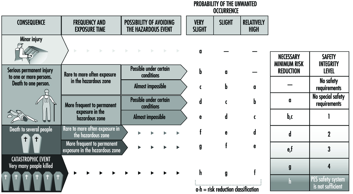
Figure 3 makes it clear that the effectiveness of measures taken, in any given case, to reduce error in software and computers needs to grow with increasing risk (DIN 1994; IEC 1993).
Figure 3, Effectiveness of precautions taken against errors independently of risk
The analysis of the accidents sketched above shows that the failure of computer-controlled safeguards is caused not only by random component faults, but also by particular operating conditions which the programmer has failed to take into account. The not immediately obvious consequences of program modifications made in the course of system maintenance constitute a further source of error. It follows that there can be failures in safety systems controlled by microprocessors which, though made during the development of the system, can lead to a dangerous situation only during operation. Precautions against such failures must therefore be taken while safety-related systems are in the development stage. These so-called failure-avoidance measures must be taken not only during the concept phase, but also in the process of development, installation and modification. Certain failures can be avoided if they are discovered and corrected during this process (DIN 1990).
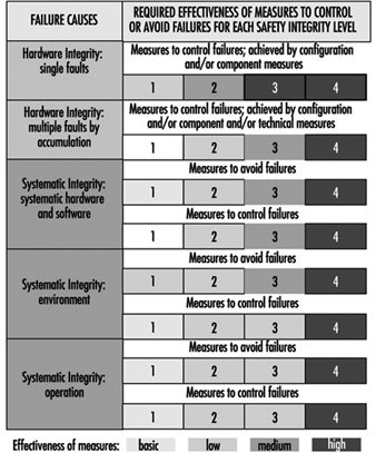
As the last mishap described makes clear, the breakdown of a single transistor can lead to the technical failure of highly complex automated equipment. Since each single circuit is composed of many thousands of transistors and other components, numerous failure-avoidance measures must be taken to recognize such failures as turn up in operation and to initiate an appropriate reaction in the computer system. Figure 4 describes types of failures in programmable electronic systems as well as examples of precautions which may be taken to avoid and control failures in computer systems (DIN 1990; IEC 1992).
Figure 4. Examples of precautions taken to control and avoid errors in computer systems

Possibilities and Prospects of Programmable Electronic Systems in Safety Technology
Modern machines and plants are becoming increasingly complex and must achieve ever more comprehensive tasks in ever shorter periods of time. For this reason, computer systems have taken over nearly all areas of industry since the mid-1970s. This increase in complexity alone has contributed significantly to the rising costs involved in improving safety technology in such systems. Although software and computers pose a great challenge to safety in the workplace, they also make possible the implementation of new error-friendly systems in the field of safety technology.
A droll but instructive verse by Ernst Jandl will help to explain what is meant by the concept error-friendly. “Lichtung: Manche meinen lechts und rinks kann man nicht velwechsern, werch ein Illtum”. (“Dilection: Many berieve light and reft cannot be intelchanged, what an ellol”.) Despite the exchange of the letters r and l, this phrase is easily understood by a normal adult human. Even someone with low fluency in the English language can translate it into English. The task is, however, nearly impossible for a translating computer on its own.
This example shows that a human being can react in a much more error-friendly fashion than a language computer can. This means that humans, like all other living creatures, can tolerate failures by referring them to experience. If one looks at the machines in use today, one can see that the majority of machines penalize user failures not with an accident, but with a decrease in production. This property leads to the manipulation or evasion of safeguards. Modern computer technology places systems at the disposal of work safety which can react intelligently—that is, in a modified way. Such systems thus make possible an error-friendly mode of behaviour in novel machines. They warn users during a wrong operation first of all and shut the machine off only when this is the only way to avoid an accident. The analysis of accidents shows that there exists in this area a considerable potential for reducing accidents (Reinert and Reuss 1991).
Devices for Controlling, Isolating and Switching Energy
Control devices and devices used for isolating and switching must always be discussed in relation to technical systems, a term used in this article to include machines, installations and equipment. Every technical system fulfils a specific and assigned practical task. Appropriate safety control and switching devices are required if this practical task is to be workable or even possible under safe conditions. Such devices are used in order to initiate control, interrupt or retard the current and/or the impulses of electric, hydraulic, pneumatic and also potential energies.
Isolation and Energy Reduction
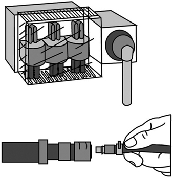
Isolating devices are used to isolate energy by disconnecting the supply line between the energy source and the technical system. The isolating device must normally yield an unequivocally determinable actual disconnection of the energy supply. Disconnection of the energy supply should also always be combined with the reduction of energy stored in all parts of the technical system. If the technical system is fed by several energy sources, all these supply lines must be capable of being reliably isolated. Persons trained to handle the relevant type of energy and who work at the energy end of the technical system, use isolation devices to shield themselves from the hazards of the energy. For safety reasons, these persons will always check to assure that no potentially hazardous energy remains in the technical system—for instance, by ascertaining the absence of electrical potential in the case of electric energy. Risk-free handling of certain isolating devices is possible only for trained specialists; in such cases, the isolating device must be made inaccessible to unauthorized persons. (See figure 1.)
Figure 1. Principles of electric and pneumatic isolating devices
The Master Switch
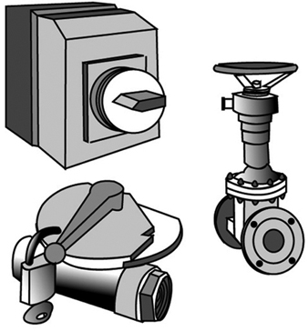
A master-switch device disconnects the technical system from the energy supply. Unlike the isolating device, it can be operated without danger even by “non-energy specialists”. The master- switch device is used to disconnect technical systems not in use at a given moment should, say, their operation be obstructed by unauthorized third persons. It is also used to effect a disconnection for such purposes as maintenance, repair of malfunctions, cleaning, resetting and refitting, provided that such work can be done without energy in the system. Naturally, when a master-switch device also possesses the characteristics of an isolating device, it can also take on and/or share its function. (See figure 2.)
Figure 2. Sample illustration of electric and pneumetic master-switch devices
Safety-disconnection Device
A safety-disconnection device does not disconnect the entire technical system from the energy source; rather, it removes energy from the parts of the system critical to a particular operational subsystem. Interventions of short duration can be designated for operational subsystems—for instance, for the set-up or resetting/refitting of the system, for the repair of malfunctions, for regular cleaning, and for essential and designated movements and function sequences required during the course of set-up, resetting/refitting or test runs. Complex production equipment and plants cannot simply be shut off with a master-switch device in these cases, as the entire technical system could not start up again where it left off after a malfunction has been repaired. Furthermore, the master-switch device is rarely located, in the more extensive technical systems, at the place where the intervention must be made. Thus the safety disconnection device is obliged to fulfil a number of requirements, such as the following:
- It interrupts the energy flow reliably and in such a way that dangerous movements or processes are not triggered by control signals which are either erroneously entered or erroneously generated.
- It is installed precisely where interruptions must be made in danger areas of operational subsystems of the technical system. If necessary, installation can be in several places (for instance, on various floors, in various rooms, or at various access points on machinery or equipment).
- Its control device has a clearly marked “off” position which registers only once after the flow of energy has been reliably cut off.
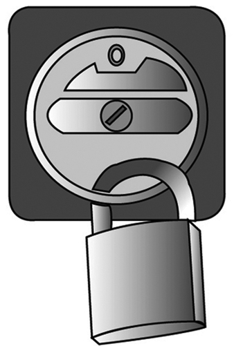
- Once in the “off” position its control device can be secured against being restarted without authorization (a) if the danger areas in question cannot be reliably overseen from the control area and (b) if persons located in the danger area cannot themselves see the control device readily and constantly, or (c) if lock-out/tag-out is required by regulation or organization procedures.
- It should disconnect only a single functional unit of an extended technical system, if other functional units are able to continue to work on their own without danger to the person intervening.
Where the master-switch device used in a given technical system is able to fulfil all the requirements of a safety-disconnection device, it can also take on this function. But that will of course be a reliable expedient only in very simple technical systems. (See figure 3.)
Figure 3. Illustration of elementary principles of a safety disconnection device
Control Gears for Operational Subsystems
Control gears permit movements and functional sequences required for operational subsystems of the technical system to be implemented and controlled safely. Control gears for operational subsystems may be required for set-up (when test runs are to be executed); for regulation (when malfunctions in the operation of the system are to be repaired or when blockages must be cleared); or training purposes (demonstrating operations). In such cases, the normal operation of the system cannot simply be restarted, as the intervening person would be endangered by movements and processes triggered by control signals either erroneously entered or erroneously generated. A control gear for operational subsystems must conform to the following requirements:
- It should permit the safe execution of movements and processes required for operational subsystems of the technical system. For example, certain movements will be executed at reduced speeds, gradually or at lower levels of power (depending on what is appropriate), and processes interrupted immediately, as a rule, if the control panel is no longer attended.
- Its control panels are to be located in areas where their operation does not endanger the operator, and from which the processes controlled are fully visible.
- If several control panels controlling various processes are present at a single location, then these must be clearly marked and arranged in a distinct and understandable manner.
- The control gear for operational subsystems should become effective only when normal operation has been reliably disengaged; that is, it must be guaranteed that no control command can issue effectively from normal operation and over-ride the control gear.
- Unauthorized use of the control gear for operational subsystems should be preventable, for instance, by requiring the use of a special key or code to release the function in question. (See figure 4.)
Figure 4. Actuating devices in the control gears for movable and stationary operational subsystems

The Emergency Switch
Emergency switches are necessary where the normal operation of technical systems could result in hazards which neither appropriate system design nor the taking of appropriate safety precautions are able to prevent. In operational subsystems, the emergency switch is frequently part of the operational subsystem control gear. When operated in case of danger, the emergency switch implements processes which return the technical system to a safe operating state as quickly as possible. With regard to safety priorities, the protection of persons is of primary concern; prevention of damage to material is secondary, unless the latter is liable to endanger persons as well. The emergency switch must fulfil the following requirements:
- It must bring about a safe operating condition of the technical system as quickly as possible.
- Its control panel must be easily recognizable and placed and designed in such a way that it can be operated without difficulty by the endangered persons and can also be reached by others responding to the emergency.
- The emergency processes it triggers must not bring about new hazards; for example, they must not release clamping devices or disconnect magnetic holding fixtures or block safety devices.
- After an emergency switch process has been triggered, the technical system must not be able to be restarted automatically by the resetting of the emergency switch control panel. Rather, the conscious entry of a new function control command must be required. (See figure 5.)
Figure 5. Illustration of the principles of control panels in emergency switches

Function-switch Control Device
Function-switch control devices are used to switch on the technical system for normal operation and to initiate, implement and interrupt the movements and processes designated for normal operation. The function-switch control device is used exclusively in the course of the normal operation of the technical system—that is, during the undisturbed execution of all assigned functions. It is used accordingly by the persons running the technical system. The function-switch control devices must meet the following requirements:
- Their control panels must be accessible and easy to use without danger.
- Their control panels must be clearly and rationally arranged; for example, control knobs should operate “rationally” with regard to controlled movements up and down, right and left. (“Rational” control movements and corresponding effects may be subject to local variation and are sometimes defined by stipulation.)
- Their control panels are to be clearly and intelligibly labelled, with symbols which are easily understood.
- Processes which require the complete attention of the user for their safe execution must not be able to be triggered either by control signals generated in error or by inadvertent operation of the control devices governing them. Control panel signal processing must be appropriately reliable, and involuntary operation must be prevented by appropriate design of the control device. (See figure 6).
Figure 6. Schematic representation of an operations control panel

Monitoring Switches
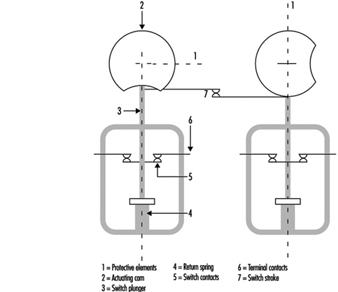
Monitoring switches prevent the starting of the technical system as long as the monitored safety conditions are not fulfilled, and they interrupt operation as soon as a safety condition is no longer being fulfilled. They are used, for example, to monitor doors in protective compartments, to check for the correct position of safety guards or to assure that speed or path limits are not exceeded. Monitoring switches must accordingly fulfil the following safety and reliability requirements:
- The switching gear used for monitoring purposes must emit the protective signal in a particularly reliable fashion; for instance, a mechanical monitoring switch might be designed to interrupt the signal flow automatically and with particular reliability.
- The switching tool used for monitoring purposes is to be operated in a particularly reliable fashion when the safety condition is not fulfilled (e.g., when the plunger of a monitoring switch with automatic interruption is forced mechanically and automatically into the interrupt position).
- The monitoring switch must not be able to be improperly turned off, at least not unintentionally and not without some effort; this condition may be fulfilled, for instance, by a mechanical, automatically controlled switch with automatic interruption, when the switch and the operating element are securely mounted. (See figure 7).
Figure 7. Diagram of a switch with a positive mechanical operation and positive disconnection
Safety Control Circuits
Several of the safety switching devices described above do not execute the safety function directly, but rather by emitting a signal which is then transmitted and processed by a safety control circuit and finally reaches those parts of the technical system which exercise the actual safety function. The safety-disconnection device, for example, frequently causes the disconnection of energy at critical points indirectly, whereas a main switch usually directly disconnects the supply of current to the technical system.
Because safety control circuits must transmit safety signals reliably, the following principles must therefore be taken into consideration:
- Safety should be guaranteed even when outside energy is lacking or insufficient, for example, during disconnects or leaks.
- Protective signals function more reliably by interruption of the signal flow; for example, safety switches with opener contact or an open relay contact.
- The protective function of amplifiers, transformers and the like may be achieved more reliably without outside energy; such mechanisms include, for example, electromagnetic switching devices or vents that are closed when at rest.
- Connections effected in error and leaks in the safety-control circuit must not be allowed to lead to false starts or hindrances to stoppage; particularly in the cases of a short circuit between in- and out-conduits, earth leakage, or grounding.
- Outside influences affecting the system in a measure not exceeding the expectations of the user should not interfere with the safety function of the safety-control circuit.
The components used in safety-control circuits must execute the safety function in an especially reliable way. The functions of components which do not meet this requirement are to be implemented by arranging for as diversified a redundancy as possible and are to be kept under surveillance.
Health and Environmental Concerns
Beverages, both alcoholic and non-alcoholic, are normally produced under strict sanitary guidelines set by governmental regulations. To meet these guidelines, equipment within beverage plants is constantly cleaned and disinfected with harsh cleaning agents. The copious use of cleaning agents can, in itself, pose health problems to the workers exposed to them in their job duties. Skin and eye contact with the caustic cleansers can cause severe dermatitis. Another concern is that inhalation of the fumes or spray produced when using the cleansers may cause damage to the lungs, nose, mouth or throat. Water or other liquids are commonly found in and around production, making slips and falls a common injury and causing many other injuries simply due to poor traction.
Glass containers, high-speed fillers and overhead conveyors result in a combination of elements that can produce serious harm from flying glass. Cuts and eye injuries are common due to glass breakage. Much of the beverage industry has moved to using larger and larger quantities of aluminium cans and plastic containers; this has reduced the incidence of glass-inflicted injuries. However, in certain countries and specific industries, such as wine and spirits, this has not been the case.
Electrical systems in any industry possess a high degree of potential injury. When mixed with the ever present water in beverage manufacturing, the threat of electrocution becomes extreme. Electrical systems within beverage plants are constantly being reworked as the industry rapidly modernizes with new high-speed equipment that results in increasing exposure.
The manufacturing process in the beverage industry entails the movement of massive quantities of raw materials in bags and barrels, on wooden and plastic pallets; loads of empty bottles and cans; and finished product in a variety of containers. Beverages, being liquid, are naturally heavy. Repetitive-motion injuries due to sorting and inspection of glass bottles and some packaging operations occur frequently. This continuous movement of light and heavy objects presents ergonomic challenges for the beverage industry as well as other industries. The incidence of soft tissue sprain and strain injuries in the United States has risen nearly 400% since 1980, for example. Nations are in different stages of progress in determining preventive measures to reduce these types of injuries.
Modern mechanized equipment has drastically reduced the number of personnel needed to operate the bottling and canning lines, which in itself has reduced the exposure to injury. However, the high-speed conveyers and automatic palletizing and de-palletizing equipment can cause serious, although less frequent, injuries. Personnel tempted to reach into a moving conveyor to put a bottle or can upright can get clothing caught and be dragged into the mechanism. Palletizers and depalletizers can become jammed, and a worker can suffer broken limbs trying to clear the machines.
Modern high-speed equipment has, in most cases, led to increased noise levels, especially at the higher frequencies. Hearing loss caused by workplace noise is classified as a disease, since it occurs insidiously over time and is irreversible. Incidence rates involving hearing loss are increasing. Engineering controls to reduce the noise levels are being tested and used, but enforcement of the wearing of standard hearing protection is still the preferred method used by most employers. New on the horizon is the investigation of the stress on workers due to the combination of high noise levels, 24-hour schedules and the tempo of work.
Confined spaces, such as tanks, casks, vats, wastewater pits and storage or mixing vessels used commonly in beverage manufacturing facilities, have the potential of causing catastrophic injuries. This issue has not received a lot of attention by beverage industry management because most vessels are considered to be “clean” and mishaps occur so infrequently. Although injuries in the types of vessels used by beverage plants are rare, a serious incident can occur due to the introduction of hazardous materials during cleaning operations or from atmospheric abnormalities, potentially resulting in a near or actual fatality. (See the box on confined spaces.)
Most beverage manufacturing facilities have raw material and finished product storage areas. Self-propelled material-handling equipment poses as serious a threat in a production plant as in any warehouse. Injuries involving fork-lift trucks and similar equipment often result in crushing injuries to pedestrian personnel or to the operator if the vehicle overturns. Production plants often entail cramped conditions as expansion of production capability in existing facilities takes place. These cramped conditions are often conducive to a serious accident involving material-handling equipment.
Beverage production usually requires pure water and refrigeration systems. Chemicals used most commonly to satisfy these requirements are chlorine and liquid anhydrous ammonia, respectively, and both are considered extremely hazardous substances. Chlorine is often purchased and stored in pressurized metal cylinders of various sizes. Injuries can occur to personnel during changeover from one cylinder to another or from a leaking or defective valve. An accidental release of anhydrous ammonia can cause burns to the skin and respiratory system on contact. A large, uncontrolled release of anhydrous ammonia can result in air concentrations high enough to explode violently. Emergency systems to detect leaks and automatic ventilation and shut down equipment are used frequently, along with evacuation and response procedures. Chlorine and anhydrous ammonia are chemicals that have strong identifiable odours and are easily detectable in the air. They are considered to have strong warning properties to alert workers of their presence.
Carbon dioxide, most commonly used for pressurization and carbonation, and carbon monoxide, emitted by internal combustion engines, are present in most beverage plants. Beverage filler rooms are usually the most prone to having high levels of carbon dioxide, especially during product changeover procedures. Beverage companies have been increasing the assortment of products offered to the public, so these changeovers occur more frequently, increasing the need for ventilation to exhaust the carbon dioxide. Carbon monoxide can be present if fork-lifts or similar equipment are used. A dangerous concentration can accumulate if engines are not operating within manufacturers’ specifications.
Employment in the beverage industry is often seasonal. This is more common in areas of the world with distinct seasons and in northern climates. A combination of worldwide manufacturing trends such as just-in-time inventory control and the use of contract and temporary personnel can have a great impact on safety and health. Often workers employed for short periods of time are not afforded the same amount of safety-related training as permanent employees. In some cases, resultant costs associated with injuries sustained by temporary personnel are not borne by the employer but by an agency supplying the worker to the employer. This has created an apparent “win-win” situation for the employer and the opposite effect on the workers employed in positions such as these. More enlightened governments, employers and trade associations are beginning to look closely at this growing problem and are working on methods to improve the amount and quality of safety training given to workers in this category.
Environmental concerns are not often associated with beverage production, since it is not thought of as a “smokestack industry”. Excluding an accidental release of a hazardous chemical such as anhydrous ammonia or chlorine, the main discharge from beverage production is wastewater. Usually this wastewater is treated prior to entry into the waste stream, so it is rare that a problem occurs. Occasionally a bad batch of product has to be discarded, which, depending on the ingredients involved, may have to be transported away for treatment or greatly diluted before release into the waste system. A large quantity of acidic beverage finding its way into a stream or lake can cause large fish kills and must be avoided.
The increasing use of chemical additives for enhancing flavour, extending shelf life or as a substitute sweetener has raised public health concerns. Some chemicals used as artificial sweeteners are prohibited in some countries because they have been found to be carcinogenic. Most, however, present no apparent health risk to the public. The handling of these raw chemicals and their presence in the workplace has not been studied in enough depth to determine if there are worker exposure risks.
Presence Detectors
General developments in microelectronics and in the technology of sensors give reason to hope that an improvement in occupational safety can be achieved through the availability of reliable, hardy, low-maintenance and inexpensive presence and approach detectors. This article will describe sensor technology, the different detection procedures, the conditions and restrictions applicable to the use of sensor systems, and some completed studies and standardization work in Germany.
Presence Detector Criteria
The development and practical testing of presence detectors is one of the greatest future challenges to technical efforts in improving occupational safety and to the protection of personnel in general. Presence detectors are sensors that reliably and with certainty signal the near presence or approach of a person. In addition, this warning must occur rapidly so that evasive action, braking or the shutting off of a stationary machine can take place before the predicted contact occurs. Whether the people are big or small, whatever their posture, or how they are clothed should have no effect on the reliability of the sensor. In addition, the sensor must possess certainty of functioning and be sturdy and inexpensive, so that it can be used under the most demanding conditions, such as on construction sites and for mobile applications, with minimal maintenance. Sensors must be like an airbag in that they are maintenance-free and always ready. Given some users’ reluctance to maintain what they may regard as nonessential equipment, sensors may be left unserviced for years. Another feature of presence detectors, one that is much more likely to be requested, is that they also detect obstacles other than human beings and alert the operator in time to take defensive action, thus reducing costs of repair and material damage. This is a reason for installing presence detectors that should not be under-appreciated.
Detector Applications
Innumerable fatal accidents and serious injuries which look like unavoidable, individual acts of fate, may be avoided or minimized provided that presence detectors become more accepted as a prevention measure in the field of occupational safety. The newspapers report these accidents all too often: here a person was struck by a backwards-moving loader, there the operator did not see someone who was run over by the front wheel of a power shovel. Trucks moving backwards on streets, company premises and construction sites are the cause of many accidents to people. Today’s thoroughly rationalized companies no longer provide co-drivers or other persons to act as guides for the driver who is backing up a truck. These examples of moving accidents can be easily extended to other mobile equipment, such as fork-lift trucks. However, the use of sensors is urgently needed to prevent accidents involving semi-mobile and purely stationary equipment. An example is the rear areas of large loading machines, which have been identified by safety personnel as potentially hazardous areas which could be improved through the use of inexpensive sensors. Many variations of presence detectors can be adapted innovatively to other vehicles and large mobile equipment to protect against the types of accidents discussed in this article, which generally cause extensive damage and serious, if not fatal, injuries.
The tendency of innovative solutions to become more widespread would seem to promise that presence detectors will become the standard safety technology in other applications; however, this is not the case anywhere. The breakthrough, motivated by accidents and high material damages, is expected in monitoring behind delivery vans and heavy trucks and for the most innovative areas of the “new technologies”—the mobile robot machines of the future.
The variation of the fields of application for presence detectors and the variability of the tasks—for example, tolerating objects (even moving objects, under certain conditions) that belong to a detection field and that should not trigger a signal—require sensors in which “intelligent” assessment technology supports the mechanisms of sensor function. This technology, which is a matter for future development, can be elaborated from methods drawing upon the field of artificial intelligence (Schreiber and Kuhn 1995). To date, a limited universality has severely restricted current uses of sensors. There are light curtains; light bars; contact mats; passive infrared sensors; ultrasound and radar motion detectors that use the Doppler effect; sensors that make elapsed time measurements of ultrasound, radar and light impulses; and laser scanners. Normal television cameras connected to monitors are not included in this list because they are not presence detectors. However, those cameras which do activate automatically upon sensing the presence of a person, are included.
Sensor Technology
Today the main sensor issues are (1) optimizing the use of the physical effects (infrared, light, ultrasound, radar, etc.) and (2) self-monitoring. Laser scanners are being intensively developed for use as navigational instruments for mobile robots. For this, two tasks, partially different in principle, must be solved: the navigation of the robot and the protection of persons (and material or equipment) present so that they are not struck, run over or grabbed (Freund, Dierks and Rossman 1993). Future mobile robots cannot retain the same safety philosophy of “spatial separation of robot and person” which is strictly applied to today’s stationary industrial robots. This means putting a high premium on the reliable functioning of the presence detector to be used.
The use of “new technology” is often linked to problems of acceptance, and it can be assumed that the general use of mobile robots that can move and grasp, among people in plants, in public traffic areas, or even in homes or recreational areas, will be accepted only if they are equipped with very highly developed, sophisticated and reliable presence detectors. Spectacular accidents must be avoided at all costs in order to avoid exacerbating a possible acceptance problem. The current level of expenditure for the development of this type of occupational protective sensors does not come close to taking this consideration into account. To save a lot of costs, presence detectors should be developed and tested simultaneously with the mobile robots and the navigational systems, not afterwards.
With respect to motor vehicles, safety questions have gained increasing significance. Innovative passenger safety in automobiles includes three-point seat belts, child seats, airbags and the anti-lock brake system verified by serial crash tests. These safety measures represent a relatively increasing portion of production costs. The side airbag and radar sensor systems to measure the distance to the car ahead are evolutionary developments in passenger protection.
External motor vehicle safety—that is, the protection of third parties—is receiving increased attention. Recently, side protection has been required, primarily for trucks, to prevent motorcyclists, bicyclists and pedestrians from the danger of falling under the rear wheels. A next logical step would be monitoring the area behind large vehicles with presence detectors and installing rear area warning equipment. This would have the positive side effect of providing the funding required to develop, test and make available maximum performance, self-monitoring, maintenance-free and reliably functioning, inexpensive sensors for occupational safety purposes. The trial process that would go with the broad implementation of sensors or sensor systems would considerably facilitate innovation in other areas, such as power shovels, heavy loaders and other large mobile machines that back up as much as half the time during their operation. The evolutionary process from stationary robots to mobile robots is an additional path of development for presence detectors. For example, improvements could be made to the sensors currently used on mobile robot material movers or “driverless factory floor tractors”, which follow fixed paths and therefore have relatively low safety requirements. The use of presence detectors is the next logical step in improving safety in the area of material and passenger transport.
Detection Procedures
Various physical principles, available in connection with electronic measuring and self-monitoring methods and, to an extent, high-performance computing procedures, may be used to assess and solve the above-mentioned tasks. The apparently effortless and sure operation of automated machines (robots) so common in science-fiction films, will possibly be accomplished in the real world through the use of imaging techniques and high-performance pattern recognition algorithms in combination with distance measurement methods analogous to those employed by laser scanners. The paradoxical situation that everything that seems simple for people is difficult for automatons, must be recognized. For example, a difficult task such as excellent chess playing (which calls for forebrain activity) can be more easily simulated and carried out by automated machines than a simple task such as walking upright or carrying out hand-eye and other movement coordination (mediated by the mid- and hindbrain). A few of these principles, methods and procedures applicable to sensor applications are described below. In addition to these, there are a large number of special procedures for very special tasks that work in part with a combination of various types of physical effects.
Light barrier curtains and bars. Among the first presence detectors were light barrier curtains and bars. They have a flat monitoring geometry; that is, one who has passed the barrier will no longer be detected. An operator’s hand, or the presence of tools or parts held in an operator’s hand, for instance, can be quickly and reliably detected with these devices. They offer an important contribution to occupational safety for machines (like presses and punching machines) that require that material be put in by hand. The reliability has to be extremely high statistically, because when the hand reaches in only two to three times per minute, about one million operations are performed in just a few years. The mutual self-monitoring of sender and receiver components has been developed to such a very high technical level that it represents a standard for all other presence detection procedures.
Contact mats (switch mats). There are both passive and active (pump) types of electric and pneumatic contact mats and floors, which were initially used in large numbers in service functions (door openers), until they were replaced by motion detectors. Further development evolves with the use of presence detectors in all sorts of danger zones. For example, the development of automated manufacturing with a change in the function of the worker—from operating the machine to strictly monitoring its function—produced a corresponding demand for appropriate detectors. Standardization of this use is well advanced (DIN 1995a), and special limitations (layout, size, maximum allowed “dead” zones) necessitated the development of expertise for installation in this area of usage.
Interesting possible uses of contact mats arise in conjunction with computer-controlled multiple robot systems. An operator switches one or two elements so that the presence detector would pick up his or her exact position and inform the computer, which manages robot control systems with a built-in collision-avoidance system. In one test advanced by the German federal safety institute (BAU), a contact-mat floor, consisting of small electrical switch mats, was built under the robot arm’s work area for this purpose (Freund, Dierks and Rossman 1993). This presence detector had the form of a chessboard. The respectively activated mat field told the computer the operator’s position (figure 1) and when the operator approached too close to the robot, it moved away. Without the presence detector the robot system would not be able to ascertain the operator’s position, and the operator then could not be protected.
Figure 1. A person (right) and two robots in computed wrapper bodies
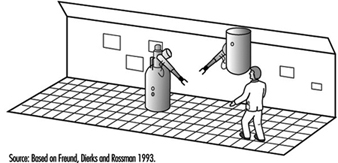
Reflectors (motion sensors and presence detectors). However meritorious the sensors discussed up to now may be, they are not presence detectors in the broader sense. Their suitability—primarily for reasons of occupational safety—for large vehicles and large mobile equipment presupposes two important characteristics: (1) the ability to monitor an area from one position, and (2) error-free functioning without the need for additional measures on the part of—for example, the use of reflector devices. Detecting the presence of a person entering the monitored area and remaining stopped until this person has gone also implies the need for detecting a person standing absolutely still. This distinguishes so-called motion sensors from presence detectors, at least in connection with mobile equipment; motion sensors are almost always triggered when the vehicle is put into motion.
Motion sensors. The two basic types of motion sensors are: (1) “passive infrared sensors” (PIRS), which react to the smallest change in the infrared beam in the monitored area (the smallest detectable beam is approximately 10-9 W with a wavelength range of approximately 7 to 20 μm); and (2) ultrasound and microwave sensors using the Doppler principle, which determines the characteristics of an object’s motion according to the frequency changes. For example, the Doppler effect increases the frequency of a locomotive’s horn for an observer when it is approaching, and reduces the frequency when the locomotive is moving away. The Doppler effect makes possible the building of relatively simple approach sensors, as the receiver needs only to monitor the signal frequency of neighbouring frequency bands for the appearance of the Doppler frequency.
In the mid-1970s the use of motion detectors became prevalent in service function applications such as door openers, theft security and object protection. For stationary use, the detection of an approaching person toward a danger spot was adequate to give a timely warning or to turn off a machine. This was the basis for studying the suitability of motion detectors for their use in occupational safety, especially by means of PIRS (Mester et al. 1980). Because a clothed person generally has a higher temperature than the surrounding area (head 34°C, hands 31°C), detecting an approaching person is somewhat easier than detecting inanimate objects. To a limited extent, machine parts can move about in the monitored area without triggering the detector.
The passive method (without transmitter) has advantages and disadvantages. The advantage is that a PIRS does not add to noise and electrical smog problems. For theft security and object protection, it is particularly important that the detector not be easy to find. A sensor that is purely a receiver, however, can hardly monitor its own effectiveness, which is essential for occupational safety. One method for overcoming this drawback was to test small modulated (5 to 20 Hz) infrared emitters that were installed in the monitored area and that did not trigger the sensor, but whose beams were registered with a fixed electronic amplification set to the modulation frequency. This modification turned it from a “passive” sensor to an “active” sensor. In this way it was also possible to check the geometric accuracy of the monitored area. Mirrors can have blind spots, and a passive sensor’s direction can be thrown off by the rough activity in a plant. Figure 2 shows a test layout with a PIRS with a monitored geometry in the form of a pyramid mantle. Because of their great reach, passive infrared sensors are installed, for example, in the passageways of shelf storage areas.
Figure 2. Passive infrared sensor as approach detector in a danger area
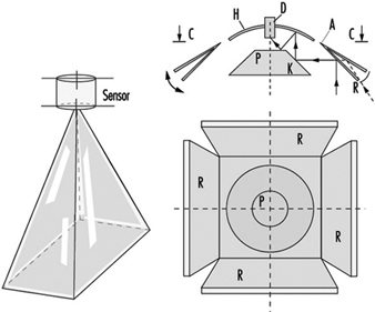
Overall, tests showed that motion detectors are not suited to occupational safety. A night-time museum floor cannot be compared to danger zones in a workplace.
Ultra-sound, radar and light-impulse detectors. Sensors that use the pulse/echo principle—that is, elapsed time measurements of ultrasound, radar or light impulses—have great potential as presence detectors. With laser scanners, light impulses can sweep in rapid succession (usually in a rotatory fashion), for example, horizontally, and with the help of a computer one can obtain a distance profile of the objects on a plane that reflect light. If, for example, not only a single line is wanted, but the entirety of what lies before the mobile robot in the area up to a height of 2 metres, then great quantities of data must be processed to depict the surrounding area. A future “ideal” presence detector will consist of a combination of the following two processes:
- A pattern-recognition process will be employed, consisting of a camera and a computer. The latter can also be a “neuronal net”.
- A laser scanning process is further required to measure distances; this takes a bearing in a three-dimensional space over from a number of individual points selected by the pattern-recognition process, established to obtain the distance and motion by speed and direction.
Figure 3 shows, from the previously cited BAU project (Freund, Dierks and Rossman 1993), the use of a laser scanner on a mobile robot that also assumes navigational tasks (via a direction-sensing beam) and collision protection for objects in the immediate vicinity (via a ground measurement beam for presence detection). Given these features, the mobile robot has the capability of active automated free driving (i.e., the ability to drive around obstacles). Technically, this is achieved by utilizing the 45° angle of the scanner rotation toward the rear on both sides (to port and starboard of the robot) in addition to the 180° angle toward the front. These beams are connected with a special mirror which acts as a light curtain on the floor in front of the mobile robot (providing a ground vision line). If a laser reflection comes from there, the robot stops. While laser and light scanners certified for occupational safety use are on the market, these presence detectors have great potential for further development.
Figure 3. Mobile robot with laser scanner for navigation and presence detection use
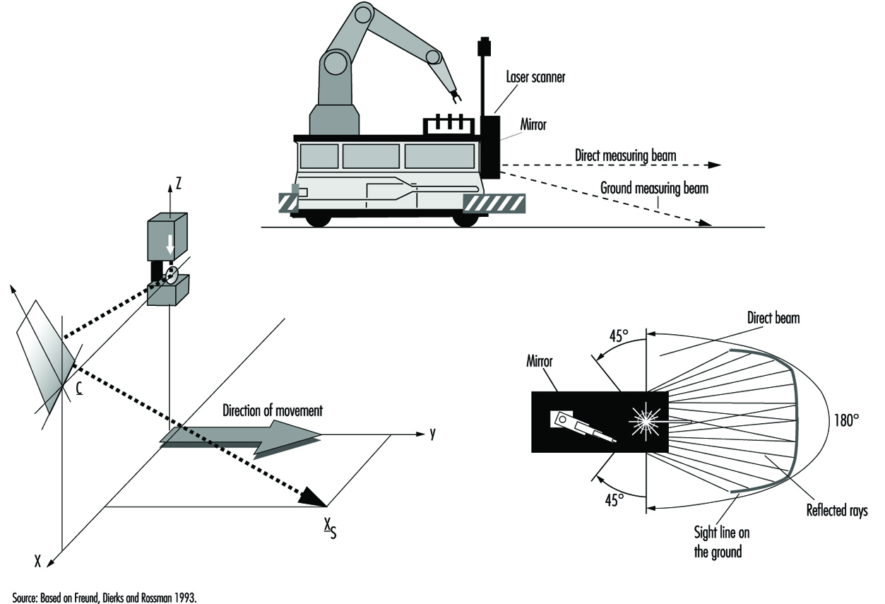
Ultrasound and radar sensors, which use the elapsed time from signal to response to determine distance, are less demanding from a technical perspective and thus can be produced more cheaply. The sensor area is club-shaped and has one or more smaller side clubs, which are symmetrically arranged. The speed of the signal’s spread (sound: 330 m/s; electromagnetic wave: 300,000 km/s) determines the requisite speed of the electronics utilized.
Rear-area warning devices. At the 1985 Hanover Exposition, BAU showed the results of an initial project on the use of ultrasound sensors for securing the area behind large vehicles (Langer and Kurfürst 1985). A full-sized model of a sensor head made of Polaroid™ sensors was set up on the back wall of a supply truck. Figure 4 shows its functioning schematically. The large diameter of this sensor produces relatively small-angled (approximately 18°), long-range club-shaped measured areas, arranged next to each other and set to different maximum signal ranges. In practice it allows one to set any desired monitored geometry, which is scanned by the sensors approximately four times per second for the presence or entrance of persons. Other demonstrated rear-area warning systems had several parallel individual arrayed sensors.
Figure 4. Disposition of measuring head and area monitored on the rear side of a truck
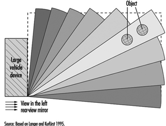
This vivid demonstration was a great success at the exhibition. It showed that securing the rear area of large vehicles and equipment is being studied in many places—for example, by specialized committees of the industrial trade associations (Berufsgenossenschaften), the municipal accident insurers (who are responsible for municipal vehicles), the state industry oversight officials, and the producers of sensors, who had been thinking more in terms of automobiles as service vehicles (in the sense of focusing on parking systems to protect against auto body damage). An ad hoc committee drawn from the groups to promote rear-area warning devices was formed spontaneously and took as a first task the preparation of a list of requirements from the perspective of occupational safety. Ten years have passed during which time much has been worked out in rear-area monitoring—possibly the most important task of presence detectors; but the big breakthrough is still missing.
Many projects have been conducted with ultrasound sensors—for example, on round-wood sorting cranes, hydraulic shovels, special municipal vehicles, and other utility vehicles, as well as on fork-lift trucks and loaders (Schreiber 1990). Rear-area warning devices are especially important for large machinery that backs up much of the time. Ultrasound presence detectors are used, for example, for the protection of specialized driverless vehicles such as robot material-handling machines. As compared to rubber bumpers, these sensors have a greater detection area which provides for braking before contact is made between the machine and an object. Corresponding sensors for automobiles are appropriate developments and involve considerably less stringent requirements.
In the meantime, the Transportation System Technical Standards Committee of DIN worked up Standard 75031, “Obstacle detection devices during reversing” (DIN 1995b). The requirements and tests were set for two ranges: 1.8 m for supply trucks and 3.0 m—an additional warning area—for larger trucks. The monitored area is set through the recognition of cylindrical test bodies. The 3-m range is also about the limit of what is presently technically possible, as ultrasound sensors must have closed metal membranes, given their rough working conditions. The requirements for the sensor system’s self-monitoring are being set, as the required monitored geometry can be accomplished only with a system of three or more sensors. Figure 5 shows a rear-area warning device consisting of three ultrasound sensors (Microsonic GmbH 1996). The same applies for the notification device in the driver’s cab and the type of warning signal. The contents of DIN Standard 75031 are also laid out in the international technical ISO Report TR 12155, “Commercial vehicles—Obstacle detection device during reversing” (ISO 1994). Various sensor producers have developed prototypes in accordance with this standard.
Figure 5. Mid-sized truck equipped with a rear area warning device (Microsonic photo).
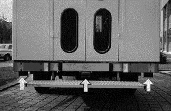
Conclusion
Since the early 1970s, several institutions and sensor manufacturers have worked to develop and establish “presence detectors”. In the special application of “rear-area warning devices” there are DIN Standard 75031 and ISO Report TR 12155. At present Deutsche Post AG is conducting a major test. Several sensor manufacturers have each equipped five mid-size trucks with such devices. A positive outcome of this test is very much in the interests of occupational safety. As was emphasized at the outset, presence detectors in the required numbers are a big challenge for safety technology in the many areas of application mentioned. They must therefore be realizable at low cost if damages to equipment, machinery and materials, and, above all, injuries to people, often very serious, are to be relegated to the past.
Brewing Industry
Adapted from 3rd edition, “Encyclopaedia of Occupational Health and Safety”.
Brewing is one of the oldest industries: beer in different varieties was drunk in the ancient world, and the Romans introduced it to all their colonies. Today it is brewed and consumed in almost every country, particularly in Europe and areas of European settlement.
Process Overview
The grain used as the raw material is usually barley, but rye, maize, rice and oatmeal are also employed. In the first stage the grain is malted, either by causing it to germinate or by artificial means. This converts the carbohydrates to dextrin and maltose, and these sugars are then extracted from the grain by soaking in a mash tun (vat or cask) and then agitating in a lauter tun. The resulting liquor, known as sweet wort, is then boiled in a copper vessel with hops, which give a bitter flavour and helps to preserve the beer. The hops are then separated from the wort and it is passed through chillers into fermenting vessels where the yeast is added—a process known as pitching—and the main process of converting sugar into alcohol is carried out. (For discussion of fermentation see the chapter Pharmaceutical industry.) The beer is then chilled to 0 °C, centrifuged and filtered to clarify it; it is then ready for dispatch by keg, bottle, aluminium can or bulk transport. Figure 1 is a flow chart of the brewing process.
Figure 1. Flow chart of the brewing process.

Hazards and Their Prevention
Manual handling
Manual handling accounts for most of the injuries in breweries: hands are bruised, cut or punctured by jagged hoops, splinters of wood and broken glass. Feet are bruised and crushed by falling or rolling barrels. Much can be done to prevent these injuries by suitable hand and foot protection. Increase in automation and standardization of barrel size (say at 50 l) can reduce the lifting risks. The back pain caused by lifting and carrying of barrels and so on can be dramatically reduced by training in sound lifting techniques. Mechanical handling on pallets can also reduce ergonomic problems. Falls on wet and slippery floors are common. Non-slip surfaces and footwear, and a regular system of cleaning, are the best precaution.
Handling of grain can produce barley itch, caused by a mite infesting the grain. Mill-worker’s asthma, sometimes called malt fever, has been recorded in grain handlers and has been shown to be an allergic response to the grain weevil (Sitophilus granarius). Manual handling of hops can produce a dermatitis due to the absorption of the resinous essences through broken or chapped skin. Preventive measures include good washing and sanitary facilities, efficient ventilation of the workrooms, and medical supervision of the workers.
When barley is malted by the traditional method of steeping it and then spreading it on floors to produce germination, it may become contaminated by Aspergillus clavatus, which can produce growth and spore formation. When the barley is turned to prevent root matting of the shoots, or when it is loaded into kilns, the spores may be inhaled by the workers. This may produce extrinsic allergic alveolitis, which in symptomatology is indistinguishable from farmer’s lung; exposure in a sensitized subject is followed by a rise in body temperature and shortness of breath. There is also a fall in normal lung functions and a decrease in the carbon monoxide transfer factor.
A study of organic dusts containing high levels of endotoxin in two breweries in Portugal found the prevalence of symptoms of organic dust toxic syndrome, which is distinct from alveolitis or hypersensitivity pneumonia, to be 18% among brewery workers. Mucous membrane irritation was found among 39% of workers (Carveilheiro et al. 1994).
In an exposed population, the incidence of the disease is about 5%, and continued exposure produces severe respiratory incapacity. With the introduction of automated malting, where workers are not exposed, this disease has largely been eliminated.
Machinery
Where malt is stored in silos, the opening should be protected and strict rules enforced regarding entry of personnel, as described in the box on confined spaces in this chapter. Conveyors are much used in bottling plants; traps in the gearing between belts and drums can be avoided by efficient machinery guarding. There should be an effective lockout/tagout programme for maintenance and repair. Where there are walkways across or above conveyors, frequent stop buttons should also be provided. In the filling process, very serious lesions can be caused by bursting bottles; adequate guards on the machinery and face guards, rubber gloves, rubberized aprons and non-slip boots for the workers can prevent injury.
Electricity
Owing to the prevailing damp conditions, electrical installations and equipment need special protection, and this applies particularly to portable apparatus. Ground fault circuit interrupters should be installed where necessary. Wherever possible, low voltages should be used, especially for portable inspection lamps. Steam is used extensively, and burns and scalds occur; lagging and protection of pipes should be provided, and safety locks on steam valves will prevent accidental release of scalding steam.
Carbon dioxide
Carbon dioxide (CO2) is formed during fermentation and is present in fermenting tuns, as well as vats and vessels that have contained beer. Concentrations of 10%, even if breathed only for a short time, produce unconsciousness, asphyxia and eventual death. Carbon dioxide is heavier than air, and efficient ventilation with extraction at a low height is essential in all fermentation chambers where open vats are used. As the gas is imperceptible to the senses, there should be an acoustic warning system which will operate immediately if the ventilation system breaks down. Cleaning of confined spaces presents serious hazards: the gas should be dispelled by mobile ventilators before workers are permitted to enter, safety belts and lifelines and respiratory protective equipment of the self-contained or supplied-air type should be available, and another worker should be posted outside for supervision and rescue, if necessary.
Gassing
Gassing has occurred during relining of vats with protective coatings containing toxic substances such as trichloroethylene. Precautions should be taken similar to those listed above against carbon dioxide.
Refrigerant gases
Chilling is used to cool the hot wort before fermentation and for storage purposes. Accidental discharge of refrigerants can produce serious toxic and irritant effects. In the past, chloromethane, bromomethane, sulphur dioxide and ammonia were mainly used, but today ammonia is most common. Adequate ventilation and careful maintenance will prevent most risks, but leak detectors and self-contained breathing apparatus should be provided for emergencies frequently tested. Precautions against explosive risks may also be necessary (e.g., flameproof electrical fittings, elimination of naked flames).
Hot work
In some processes, such as cleaning out mash tuns, workers are exposed to hot, humid conditions while performing heavy work; cases of heat stroke and heat cramps can occur, especially in those new to the work. These conditions can be prevented by increased salt intake, adequate rest periods and the provision and use of shower baths. Medical supervision is necessary to prevent mycoses of the feet (e.g., athlete’s foot), which spread rapidly in hot, humid conditions.
Throughout the industry, temperature and ventilation control, with special attention to the elimination of steam vapour, and the provision of PPE are important precautions, not only against accident and injury but also against more general hazards of damp, heat and cold (e.g., warm working clothes for workers in cold rooms).
Control should be exercised to prevent excessive consumption of the product by the persons employed, and alternative hot beverages should be available at meal breaks.
Noise
When metal barrels replaced wooden casks, breweries were faced with a severe noise problem. Wooden casks made little or no noise during loading, handling or rolling, but metal casks when empty create high noise levels. Modern automated bottling plants generate a considerable volume of noise. Noise can be reduced by the introduction of mechanical handling on pallets. In the bottling plants, the substitution of nylon or neoprene for metal rollers and guides can substantially reduce the noise level.
Wine Industry
Adapted from 3rd edition, “Encyclopaedia of Occupational Health and Safety”.
Wine is produced from grapes. The ripe grape, when crushed, yields the must which, by total or partial and normal fermentation, turns into wine. During fermentation, first rapid and turbulent, then gradually slowing down, sugar is transformed into alcohol and carbon dioxide. Many elements contained in the grapes remain in the drink. The various phases of activity in the production of wine from grapes include wine-making, storage and bottling.
Wine-making
Wine-making involves a variety of activities carried out by a variety of methods ranging from traditional “farm production” to modern industrial production. The ancient method of pressing the grapes, in which the harvesters trod during the night the grapes they had gathered during the day, is less and less seen in modern wine-making. Wine is now produced in installations belonging to groups of farmers or to commercial firms, using techniques that produce a more uniform type of wine and reduce the risk of spoilage, especially that which arises from acidification which transforms the wine into vinegar.
On arrival at the cellars, the grapes are crushed in simple mills or large machines, such as centrifugal crushers, by rollers or in other ways. These processes always involve mechanical risks and noise for the entire period during which large quantities of must is being handled. The crushed mass is then transferred to large reservoirs, by pumping or other procedures, where it will be pressed to separate the juice from the skins and stalks. The must is then transferred to fermenting vessels. On completion of fermentation, the wine is drawn off from the dregs and poured into storage bins or tanks. Extraneous matter and impurities are removed by filters. Diatomaceous earth has replaced asbestos as a filter agent in some countries, such as the United States. Larger foreign matter may be removed by centrifuges.
The quality of the wine can be improved by refrigeration using continuous-flow refrigerators and double-jacketed cooling tanks. In these operations, exposure to vapours and gases released during the various stages of the process—particularly straining, fermentation and the use of disinfectants and other products intended to guarantee the hygienic condition and quality of the wine—must be borne in mind. Refrigerant gases such as ammonia may cause toxic and explosive risks, and adequate ventilation and strict maintenance to prevent leakage are essential. Automatic leak detection and respiratory protective equipment, frequently tested, should be available for emergencies. There are also the common risks due to wet and slippery floors, the disorder characteristic of seasonal activities and the quality of illumination and ventilation (the rooms where the wine is prepared are often also used for storage and are designed to maintain a uniform, relatively low temperature).
Particularly significant are the risks of asphyxiation from the vapours of alcohol and the carbon dioxide released by the fermentation process, especially when the liquids are transported and decanted into reservoirs or confined spaces where ventilation is inadequate.
Certain other harmful substances are used in wine-making. Metabisulphite in concentrated solution is irritating to the skin and the mucous membrane; tartaric acid, which is considered non-toxic, can be slightly irritating in very concentrated solutions; sulphur dioxide provokes an intense irritation of the eyes and the respiratory tract; tannins can dry a worker’s skin and make it lose pigmentation; the use of disinfectants and detergents for the washing of storage tanks cause dermatitis; and potassium bitartarate, ascorbic acid, proteolytic enzymes and so on, which may be used in the preparation of alcoholic beverages, can cause diarrhoea or allergic reactions.
When work processes are modernized, workers may need support and assistance in order to adapt. Large production cellars should consider ergonomic principles in the choice of the equipment for such installations. Crushers and presses should have easy access in order to facilitate pouring the grapes and the residues. Whenever possible, suitable pumps should be installed, which should be easy to inspect and should have a solid foundation in order not to cause any obstruction, high noise levels and vibrations.
The general organization of the production cellar should be such that no unnecessary risks are caused and that risks should not spread to other areas; ventilation should conform to standards; temperature control may be necessary; compressors, condensers, electrical equipment and so on must be installed so as to obviate all possible risks. Because of the humidity of several processes, protecting electrical equipment is necessary and, where possible, low voltages should be used, especially for portable equipment and inspection lamps. Ground fault circuit interrupters should be installed where necessary. Electrical equipment in the vicinity of distillation plants should be of flameproof construction.
Wooden vats are decreasingly common, though they can occasionaly be found in small cellars for farm production. In modern wine-making, vats are lined with glass or stainless steel for sanitary and control reasons; lined reinforced concrete and, sometimes, plastics are also used. Vats must have the proper dimensions and be adequately resistant to allow fermentation and decanting (right down to the dregs), to hold the volume of reserves as long as necessary and to allow for easy exchange of their contents, should it prove to be necessary. Cleaning of containers involves especially high risks, and a confined-space programme should be in effect: the gas should be dispelled by mobile ventilators before containers are entered, and safety belts and life-lines and respiratory protective equipment should be worn. A competent worker should be stationed outside to supervise and rescue workers inside, if necessary. See the box on confined spaces for more information.
Wine Storage
Storage involves not only the keeping of large volumes of liquid but also a number of activities such as cleaning and disinfecting the tanks or casks; their maintenance and conservation; application of sulphur dioxide, ascorbic acid, tartaric acid, inert gases, tannins and albumins; and other additional processes, such as mixing, glueing, filtering, centrifugation and so on. Some treatments of wine involve the use of heat and cold to destroy yeast and bacteria; the utilization of carbon and other deodorizers; the application of CO2, and so on. As an example of this type of installation we may refer to the system of instantaneous refrigeration, for the stabilization of wines at a temperature near the freezing point, which facilitates the elimination of colloids, microbes and other products such as potassium bitartarate, which provokes precipitation in the bottles. It is obvious that these installations imply risks that formerly did not need to be considered in this phase of storage. Prevention is essentially based on ergonomic planning and good maintenance.
Wine Bottling
Wine is usually sold in glass bottles (of 1.0, 0.8, 0.75 or 0.30 l capacity); glass containers of 5 l are occasionally used. Plastic containers are not as common. In the filling plants, bottles are first cleaned and then filled, sealed and labelled. Conveyors are widely used in bottling plants.
The risks of bottling arise from the handling of glass material; these vary according to whether the bottles to be washed are new or returned, and according to the products used (water and detergents) and the techniques applied (washing by hand or mechanically or both). Bottles’ shape; how the filling must be done (ranging from manual methods to sophisticated filling machines which can also introduce carbon dioxide); the process of corking; the more or less complicated system of stacking, or placing into boxes or crates after labelling; and other final touches determine the risks.
The risks involved are those which generally correspond to the filling of containers with liquids. The hands are constantly wet; if the bottles break, the projection of glass particles and liquid can cause injuries. The effort required to transport them once they are packed in boxes (usually by dozens) could be eliminated at least partially by mechanization. See also the article “Soft drink bottling and canning”.
Acknowledgments: The author would like to thank the Junta Nacional dos Vinhos (Lisbon) for their advice on technical aspects.
Machine Safeguarding
There seem to be as many potential hazards created by moving machine parts as there are different types of machines. Safeguards are essential to protect workers from needless and preventable machinery-related injuries. Therefore, any machine part, function or process which may cause injury should be safeguarded. Where the operation of a machine or accidental contact with it can injure the operator or others in the vicinity, the hazard must be either controlled or eliminated.
Mechanical Motions and Actions
Mechanical hazards typically involve dangerous moving parts in the following three basic areas:
- the point of operation, that point where work is performed on the material, such as cutting, shaping, punching, stamping, boring or forming of stock
- power transmission apparatus, any components of the mechanical system which transmit energy to the parts of the machine performing the work. These components include flywheels, pulleys, belts, connecting rods, couplings, cams, spindles, chains, cranks and gears
- other moving parts, all parts of the machine which move while the machine is working, such as reciprocating, rotating and transversely moving parts, as well as feed mechanisms and auxiliary parts of the machine.
A wide variety of mechanical motions and actions which may present hazards to workers include the movement of rotating members, reciprocating arms, moving belts, meshing gears, cutting teeth and any parts that impact or shear. These different types of mechanical motions and actions are basic to nearly all machines, and recognizing them is the first step toward protecting workers from the hazards they may present.
Motions
There are three basic types of motion: rotating, reciprocating and transverse.
Rotating motion can be dangerous; even smooth, slowly rotating shafts can grip clothing and force an arm or hand into a dangerous position. Injuries due to contact with rotating parts can be severe (see figure 1).
Figure 1. Mechanical punch press

Collars, couplings, cams, clutches, flywheels, shaft ends, spindles and horizontal or vertical shafting are some examples of common rotating mechanisms which may be hazardous. There is added danger when bolts, nicks, abrasions and projecting keys or set screws are exposed on rotating parts on machinery, as shown in figure 2.
Figure 2. Examples of hazardous projections on rotating parts
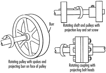
In-running nip points are created by rotating parts on machinery. There are three main types of in-running nip points:
- Parts with parallel axes can rotate in opposite directions. These parts may be in contact (thereby producing a nip point) or in close proximity to each other, in which case the stock fed between the rolls produces the nip points. This danger is common on machinery with intermeshing gears, rolling mills and calenders, as shown in figure 3.
- Another type of nip point is created between rotating and tangentially moving parts, such as the point of contact between a power transmission belt and its pulley, a chain and a sprocket, or a rack and pinion, as shown in figure 4.
- Nip points can also occur between rotating and fixed parts which create a shearing, crushing or abrading action. Examples include handwheels or flywheels with spokes, screw conveyors or the periphery of an abrasive wheel and an incorrectly adjusted work rest, as shown in figure 5.
Figure 3. Common nip points on rotating parts
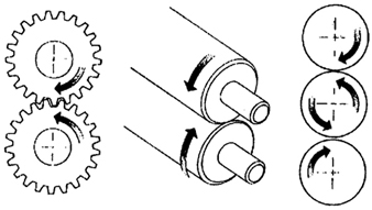
Figure 4. Nip points between rotating elements and parts with longitudinal motions

Figure 5. Nip points between rotating machine components
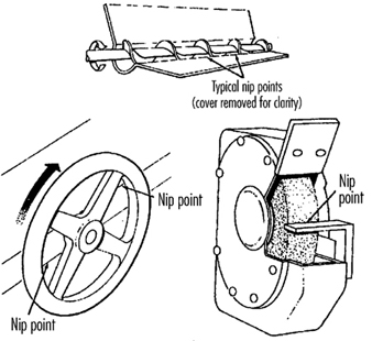
Reciprocating motions may be hazardous because during the back-and-forth or up-and-down motion, a worker may be struck by or caught between a moving part and a stationary part. An example is shown in figure 6.
Figure 6. Hazardous reciprocating motion
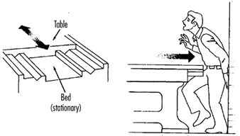
Transverse motion (movement in a straight, continuous line) creates a hazard because a worker may be struck or caught in a pinch or shear point by a moving part. An example of transverse motion is shown in figure 7.
Figure 7. Example of transverse motion
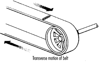
Actions
There are four basic types of action: cutting, punching, shearing and bending.
Cutting action involves rotating, reciprocating or transverse motion. Cutting action creates hazards at the point of operation where finger, head and arm injuries can occur and where flying chips or scrap material can strike the eyes or face. Typical examples of machines with cutting hazards include band saws, circular saws, boring or drilling machines, turning machines (lathes) and milling machines. (See figure 8.)
Figure 8. Examples of cutting hazards
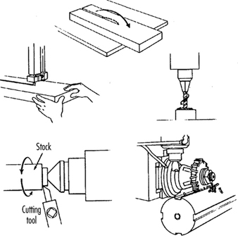
Punching action results when power is applied to a slide (ram) for the purpose of blanking, drawing or stamping metal or other materials. The danger of this type of action occurs at the point of operation where stock is inserted, held and withdrawn by hand. Typical machines which use punching action are power presses and iron workers. (See figure 9.)
Figure 9. Typical punching operation

Shearing action involves applying power to a slide or knife in order to trim or shear metal or other materials. A hazard occurs at the point of operation where stock is actually inserted, held and withdrawn. Typical examples of machinery used for shearing operations are mechanically, hydraulically or pneumatically powered shears. (See figure 10.)
Figure 10. Shearing operation
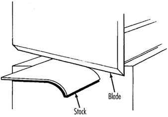
Bending action results when power is applied to a slide in order to shape, draw or stamp metal or other materials. The hazard occurs at the point of operation where stock is inserted, held and withdrawn. Equipment that uses bending action includes power presses, press brakes and tubing benders. (See figure 11.)
Figure 11. Bending operation
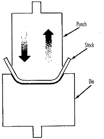
Requirements for Safeguards
Safeguards must meet the following minimum general requirements to protect workers against mechanical hazards:
Prevent contact. The safeguard must prevent hands, arms or any part of a worker’s body or clothing from making contact with dangerous moving parts by eliminating the possibility of the operators or other workers placing parts of their bodies near hazardous moving parts.
Provide security. Workers should not be able to easily remove or tamper with the safeguard. Guards and safety devices should be made of durable material that will withstand the conditions of normal use and that are firmly secured to the machine.
Protect from falling objects. The safeguard should ensure that no objects can fall into moving parts and damage the equipment or become a projectile that could strike and injure someone.
Not create new hazards. A safeguard defeats its purpose if it creates a hazard of its own, such as a shear point, a jagged edge or an unfinished surface. The edges of guards, for example, should be rolled or bolted in such a way that they eliminate sharp edges.
Not create interference. Safeguards which impede workers from performing their jobs might soon be overridden or disregarded. If possible, workers should be able to lubricate machines without disengaging or removing safeguards. For example, locating oil reservoirs outside the guard, with a line leading to the lubrication point, will reduce the need to enter the hazardous area.
Safeguard Training
Even the most elaborate safeguarding system cannot offer effective protection unless workers know how to use it and why. Specific and detailed training is an important part of any effort to implement safeguarding against machine-related hazards. Proper safeguarding may improve productivity and enhance efficiency since it may relieve workers’ apprehensions about injury. Safeguard training is necessary for new operators and maintenance or set-up personnel, when any new or altered safeguards are put in service, or when workers are assigned to a new machine or operation; it should involve instruction or hands-on training in the following:
- a description and identification of the hazards associated with particular machines and the specific safeguards against each hazard
- how the safeguards provide protection; how to use the safeguards and why
- how and under what circumstances safeguards can be removed, and by whom (in most cases, repair or maintenance personnel only)
- what to do (e.g., contact the supervisor) if a safeguard is damaged, missing or unable to provide adequate protection.
Methods of Machine Safeguarding
There are many ways to safeguard machinery. The type of operation, the size or shape of stock, the method of handling, the physical layout of the work area, the type of material and production requirements or limitations will help to determine the appropriate safeguarding method for the individual machine. The machine designer or safety professional must choose the most effective and practical safeguard available.
Safeguards may be categorized under five general classifications: (1) guards, (2) devices, (3) separation, (4) operations and (5) other.
Safeguarding with guards
There are four general types of guards (barriers which prevent access to danger areas), as follows:
Fixed guards. A fixed guard is a permanent part of the machine and is not dependent upon moving parts to perform its intended function. It may be constructed of sheet metal, screen, wire cloth, bars, plastic or any other material that is substantial enough to withstand whatever impact it may receive and to endure prolonged use. Fixed guards are usually preferable to all other types because of their relative simplicity and permanence (see table 1).
Table 1. Machine guards
|
Method |
Safeguarding action |
Advantages |
Limitations |
|
Fixed |
· Provides a barrier |
· Suits many specific applications |
· May interfere with visibility |
|
Interlocked |
· Shuts off or disengages power and prevents starting of machine when guard is open; should require the machine to be stopped before the worker can reach into the danger area |
· Provides maximum protection |
· Requires careful adjustment and maintenance |
|
Adjustable |
· Provides a barrier which may be adjusted to facilitate a variety of production operations |
· Can be constructed to suit many specific applications |
· Operator may enter danger area: protection may not be complete at all times |
|
Self-adjusting |
· Provides a barrier which moves according to the size of the stock entering danger area |
· Off-the-shelf guards are commercially available |
· Does not always provide maximum protection |
In figure 12, a fixed guard on a power press completely encloses the point of operation. The stock is fed through the side of the guard into the die area, with the scrap stock exiting on the opposite side.
Figure 12. Fixed guard on power press
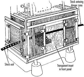
Figure 13 depicts a fixed enclosure guard which shields the belt and pulley of a power transmission unit. An inspection panel is provided on top to minimize the need for removing the guard.
Figure 13. Fixed guard enclosing belts and pulleys
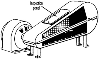
In figure 14, fixed enclosure guards are shown on a bandsaw. These guards protect operators from the turning wheels and moving saw blade. Normally, the only time the guards would be opened or removed would be for a blade change or for maintenance. It is very important that they be securely fastened while the saw is in use.
Figure 14. Fixed guards on band-saw
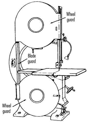
Interlocked guards. When interlocked guards are opened or removed, the tripping mechanism and/or power automatically shuts off or disengages, and the machine cannot cycle or be started until the interlock guard is back in place. However, replacing the interlock guard should not automatically restart the machine. Interlocked guards may use electrical, mechanical, hydraulic or pneumatic power, or any combination of these. Interlocks should not prevent “inching” (i.e., gradual progressive movements) by remote control, if required.
An example of an interlocking guard is shown in figure 15. In this figure, the beater mechanism of a picker machine (used in the textile industry) is covered by an interlocked barrier guard. This guard cannot be raised while the machine is running, nor can the machine be restarted with the guard in the raised position.
Figure 15. Interlocked guard on picker machine
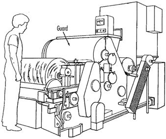
Adjustable guards. Adjustable guards allow flexibility in accommodating various sizes of stock. Figure 16 shows an adjustable enclosure guard on a band-saw.
Figure 16. Adjustable guard on band-saw

Self-adjusting guards. The openings of self-adjusting guards are determined by the movement of the stock. As the operator moves the stock into the danger area, the guard is pushed away, providing an opening which is large enough to admit only the stock. After the stock is removed, the guard returns to the rest position. This guard protects the operator by placing a barrier between the danger area and the operator. The guards may be constructed of plastic, metal or other substantial material. Self-adjusting guards offer different degrees of protection.
Figure 17 shows a radial-arm saw with a self-adjusting guard. As the blade is pulled across the stock, the guard moves up, staying in contact with the stock.
Figure 17. Self-adjusting guard on radial-arm saw
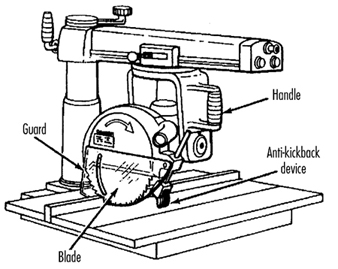
Safeguarding with devices
Safety devices may stop the machine if a hand or any part of the body is inadvertently placed in the danger area, may restrain or withdraw the operator’s hands from the danger area during operation, may require the operator to use both hands on machine controls simultaneously (thus keeping both hands and body out of danger) or may provide a barrier which is synchronized with the operating cycle of the machine in order to prevent entry to the danger area during the hazardous part of the cycle. There are five basic types of safety devices, as follows:
Presence-sensing devices
Three types of sensing devices which stop the machine or interrupt the work cycle or operation if a worker is within the danger zone are described below:
The photoelectric (optical) presence-sensing device uses a system of light sources and controls which can interrupt the machine’s operating cycle. If the light field is broken, the machine stops and will not cycle. This device should be used only on machines which can be stopped before the worker reaches the danger area. Figure 18 shows a photoelectric presence-sensing device used with a press brake. The device may be swung up or down to accommodate different production requirements.
Figure 18. Photoelectric presence-sensing device on press brake
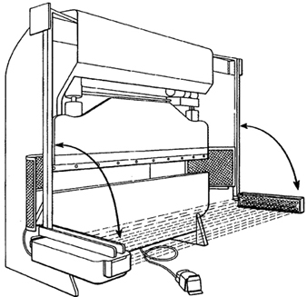
The radio-frequency (capacitance) presence-sensing device uses a radio beam that is part of the control circuit. When the capacitance field is broken, the machine will stop or will not activate. This device should be used only on machines which can be stopped before the worker can reach the danger area. This requires the machine to have a friction clutch or other reliable means for stopping. Figure 19 shows a radio-frequency presence-sensing device mounted on a part-revolution power press.
Figure 19. Radio-frequency presence-sensing device on power saw
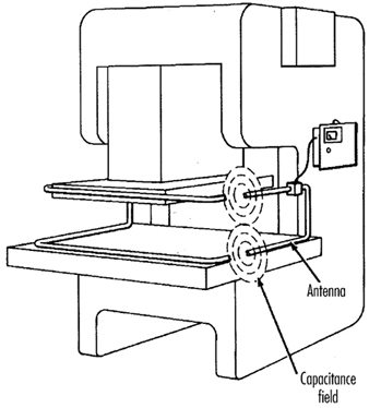
The electro-mechanical sensing device has a probe or contact bar which descends to a predetermined distance when the operator initiates the machine cycle. If there is an obstruction preventing it from descending its full predetermined distance, the control circuit does not actuate the machine cycle. Figure 20 shows an electro-mechanical sensing device on an eyeletter. The sensing probe in contact with the operator’s finger is also shown.
Figure 20. Electromechanical sensing device on eye-letter machine

Pullback devices
Pullback devices utilize a series of cables attached to the operator’s hands, wrists and/or arms and are primarily used on machines with stroking action. When the slide/ram is up, the operator is allowed access to the point of operation. When the slide/ram begins to descend, a mechanical linkage automatically assures withdrawal of the hands from the point of operation. Figure 21 shows a pullback device on a small press.
Figure 21. Pullback device on power press
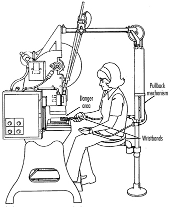
Restraint devices
Restraint devices, which utilize cables or straps that are attached between a fixed point and the operator’s hands, have been used in some countries. These devices are not generally considered to be acceptable safeguards because they are easily bypassed by the operator, thus allowing hands to be placed into the danger zone. (See table 2.)
Table 2. Devices
|
Method |
Safeguarding action |
Advantages |
Limitations |
|
Photoelectric |
· Machine will not start cycling when the light field is interrupted |
· Can allow freer movement for operator |
· Does not protect against mechanical failure |
|
Radio frequency |
· Machine cycling will not start when the capacitance field is interrupted |
· Can allow freer movement for operator |
· Does not protect against mechanical failure |
|
Electro-mechanical |
· Contact bar or probe travels a predetermined distance between the operator and the danger area |
· Can allow access at the point of operation |
· Contact bar or probe must be properly adjusted for each application; this adjustment must be maintained properly |
|
Pullback |
· As the machine begins to cycle, the operator’s hands are pulled out of the danger area |
· Eliminates the need for auxiliary barriers or other interference at the danger area |
· Limits movement of operator |
|
Safety trip controls: |
· Stops machine when tripped |
· Simplicity of use |
· All controls must be manually activated |
|
Two-hand control |
· Concurrent use of both hands is required, preventing the operator from entering the danger area |
· Operator’s hands are at a predetermined location away from danger area |
· Requires a partial cycle machine with a brake |
|
Two-hand trip |
· Concurrent use of two hands on separate controls prevent hands from being in danger area when machine cycle starts |
· Operator’s hands are away from danger area |
· Operator may try to reach into danger area after tripping machine |
|
Gate |
· Provides a barrier between danger area and operator or other personnel |
· Can prevent reaching into or walking into the danger area |
· May require frequent inspection and regular maintenance |
Safety control devices
All of these safety control devices are activated manually and must be manually reset to restart the machine:
- Safety trip controls such as pressure bars, trip rods and tripwires are manual controls which provide a quick means for deactivating the machine in an emergency situation.
- Pressure-sensitive body bars, when depressed, will deactivate the machine if the operator or anyone trips, loses balance or is drawn toward the machine. The positioning of the bar is critical, as it must stop the machine before a part of the body reaches the danger area. Figure 22 shows a pressure-sensitive body bar located on the front of a rubber mill.
Figure 22. Pressure-sensitive body bar on rubber mill
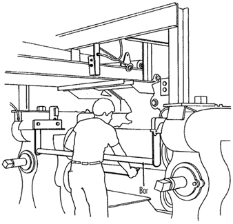
- Safety trip-rod devices deactivate the machine when pressed by hand. Because they have to be actuated by the operator during an emergency situation, their proper position is critical. Figure 23 shows a trip-rod located above the rubber mill.
Figure 23. Safety trip-rod on rubber mill
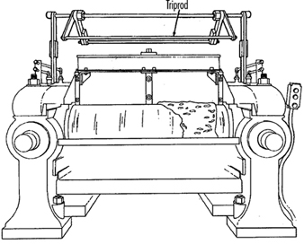
- Safety tripwire cables are located around the perimeter of, or near the danger area. The operator must be able to reach the cable with either hand to stop the machine. Figure 24 shows a calender equipped with this type of control.
Figure 24. Safety tripwire cable on calender
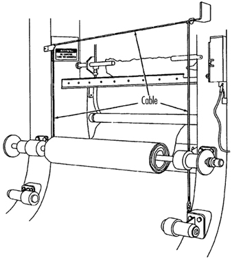
- Two-hand controls require constant, concurrent pressure for the operator to activate the machine. When installed on power presses, these controls use a part-revolution clutch and a brake monitor, as shown in figure 25. With this type of device, the operator’s hands are required to be at a safe location (on control buttons) and at a safe distance from the danger area while the machine completes its closing cycle.
Figure 25. Two-hand control buttons on part-revolution clutch power press
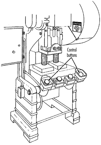
- Two-hand trip. The two-hand trip shown in figure 26 is usually used with machines equipped with full-revolution clutches. It requires concurrent application of both of the operator’s control buttons to activate the machine cycle, after which the hands are free. The trips must be placed far enough from the point of operation to make it impossible for operators to move their hands from the trip buttons or handles into the point of operation before the first half of the cycle is completed. The operator’s hands are kept far enough away to prevent them from being accidentally placed in the danger area before the slide/ram or blade reaches the full down position.
Figure 26. Two-hand control buttons on full-revolution clutch power press
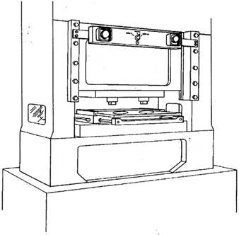
- Gates are safety control devices which provide a movable barrier that protects the operator at the point of operation before the machine cycle can be started. Gates are often designed to be operated with each machine cycle. Figure 27 shows a gate on a power press. If the gate is not permitted to descend to the fully closed position, the press will not function. Another application of gates is their use as a component of a perimeter safeguarding system, where the gates provide protection to the operators and to pedestrian traffic.
Figure 27. Power press with gate
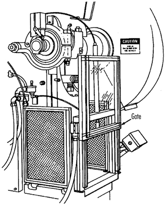
Safeguarding by location or distance
To safeguard a machine by location, the machine or its dangerous moving parts must be so positioned that hazardous areas are not accessible or do not present a hazard to a worker during the normal operation of the machine. This may be accomplished with enclosure walls or fences that restrict access to machines, or by locating a machine so that a plant design feature, such as a wall, protects the worker and other personnel. Another possibility is to have dangerous parts located high enough to be out of the normal reach of any worker. A thorough hazard analysis of each machine and particular situation is essential before attempting this safeguarding technique. The examples mentioned below are a few of the numerous applications of the principle of safeguarding by location/distance.
Feeding process. The feeding process can be safeguarded by location if a safe distance can be maintained to protect the worker’s hands. The dimensions of the stock being worked on may provide adequate safety. For example, when operating a single-end punching machine, if the stock is several feet long and only one end of the stock is being worked on, the operator may be able to hold the opposite end while the work is being performed. However, depending upon the machine, protection might still be required for other personnel.
Positioning controls. The positioning of the operator’s control station provides a potential approach to safeguarding by location. Operator controls may be located at a safe distance from the machine if there is no reason for the operator to be in attendance at the machine.
Feeding and ejection safeguarding methods
Many feeding and ejection methods do not require the operators to place their hands in the danger area. In some cases, no operator involvement is necessary after the machine is set up, whereas in other situations, operators can manually feed the stock with the assistance of a feeding mechanism. Furthermore, ejection methods may be designed which do not require any operator involvement after the machine starts to function. Some feeding and ejection methods may even create hazards themselves, such as a robot which may eliminate the need for an operator to be near the machine but may create a new hazard by the movement of its arm. (See table 3.)
Table 3. Feeding and ejection methods
|
Method |
Safeguarding action |
Advantages |
Limitations |
|
Automatic feed |
· Stock is fed from rolls, indexed by machine mechanism, etc. |
· Eliminates the need for operator involvement in the danger area |
· Other guards are also required for operator protection—usually fixed barrier guards |
|
Semi-automatic |
· Stock is fed by chutes, movable dies, dial |
· Eliminates the need for operator involvement in the danger area |
· Other guards are also required for operator protection—usually fixed barrier guards |
|
Automatic |
· Work pieces are ejected by air or mechanical means |
· Eliminates the need for operator involvement in the danger area |
· May create a hazard of blowing chips or debris |
|
Semi-automatic |
· Work pieces are ejected by mechanical |
· Operater does not have to enter danger area to remove finished work |
· Other guards are required for operator |
|
Robots |
· They perform work usually done by operator |
· Operator does not have to enter danger area |
· Can create hazards themselves |
Using one of the following five feeding and ejection methods to safeguard machines does not eliminate the need for guards and other devices, which must be used as necessary to provide protection from exposure to hazards.
Automatic feed. Automatic feeds reduce the operator exposure during the work process, and often do not require any effort by the operator after the machine is set up and running. The power press in figure 28 has an automatic feeding mechanism with a transparent fixed enclosure guard at the danger area.
Figure 28. Power press with automatic feed
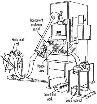
Semi-automatic feed. With semi-automatic feeding, as in the case of a power press, the operator uses a mechanism to place the piece being processed under the ram at each stroke. The operator does not need to reach into the danger area, and the danger area is completely enclosed. Figure 29 shows a chute feed into which each piece is placed by hand. Using a chute feed on an inclined press not only helps centre the piece as it slides into the die, but may also simplify the problem of ejection.
Figure 29. Power press with chute feed
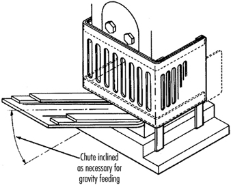
Automatic ejection. Automatic ejection may employ either air pressure or a mechanical apparatus to remove the completed part from a press, and may be interlocked with the operating controls to prevent operation until part ejection is completed. The pan shuttle mechanism shown in figure 30 moves under the finished part as the slide moves toward the up position. The shuttle then catches the part stripped from the slide by the knockout pins and deflects it into a chute. When the ram moves down toward the next blank, the pan shuttle moves away from the die area.
Figure 30. Shuttle ejection system
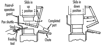
Semi-automatic ejection. Figure 31 shows a semi-automatic ejection mechanism used on a power press. When the plunger is withdrawn from the die area, the ejector leg, which is mechanically coupled to the plunger, kicks the completed work out.
Figure 31. Semi-automatic ejection mechanism
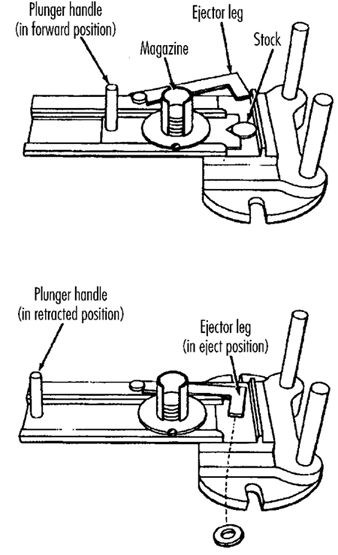
Robots. Robots are complex devices that load and unload stock, assemble parts, transfer objects or perform work otherwise done by an operator, thereby eliminating operator exposure to hazards. They are best used in high-production processes requiring repeated routines, where they can guard against other hazards to employees. Robots may create hazards, and appropriate guards must be used. Figure 32 shows an example of a robot feeding a press.
Figure 32. Using barrier guards to protect robot envelope
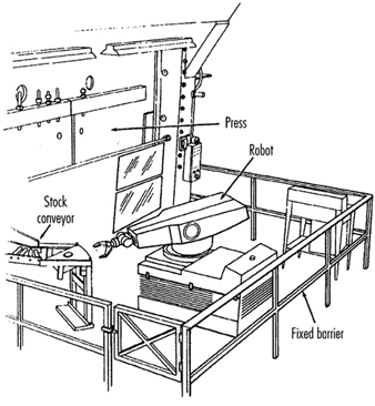
Miscellaneous safeguarding aids
Although miscellaneous safeguarding aids do not give complete protection from machine hazards, they may provide operators with an extra margin of safety. Sound judgement is needed in their application and use.
Awareness barriers. Awareness barriers do not provide physical protection, but serve only to remind operators that they are approaching the danger area. Generally, awareness barriers are not considered adequate when continual exposure to the hazard exists. Figure 33 shows a rope used as an awareness barrier on the rear of a power squaring shear. Barriers do not physically prevent persons from entering danger areas, but only provide awareness of the hazard.
Figure 33. Rear view of power shearing square
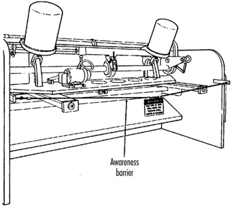
Shields. Shields may be used to provide protection from flying particles, splashing metal-working fluids or coolants. Figure 34 shows two potential applications.
Figure 34. Applications of shields
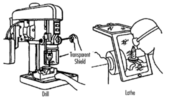
Holding tools. Holding tools place and remove stock. A typical use would be for reaching into the danger area of a press or press brake. Figure 35 shows an assortment of tools for this purpose. Holding tools should not be used instead of other machine safeguards; they are merely a supplement to the protection that other guards provide.
Figure 35. Holding tools
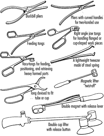
Push sticks or blocks, such as shown in figure 36, may be used when feeding stock into a machine, such as a saw blade. When it becomes necessary for hands to be in close proximity to the blade, the push stick or block may provide a margin of safety and prevent injury.
Figure 36. Use of push stick or push block

Distilled Spirits Industry
Distilled spirits can be produced from any number of materials, such as fermented mashes of cereal grains, fermented fruit juices, sugar cane juice, molasses, honey and cactus juice. Fermentation for making wine and beer can be traced back to between 5000 and 6000 BC; however, the history of distillation is much more recent. Although it is uncertain where distillation originated, it was known to alchemists and began to spread in use throughout the thirteenth and fourteenth century. Early uses were primarily pharmaceutical.
Process Overview
Alcoholic beverages are divided into two groups, depending on their mode of preparation: fermented beverages, such as wine and beer, and distilled beverages, such as whisky and brandy. Liqueurs are basically prepared by blending juices or extracts of fruits, nuts or other food products. Wine and beer making are discussed in separate articles in this chapter.
The phases of activity in distilled spirits production include receiving of grain, milling, cooking, fermentation, distillation, storage, blending and bottling (see figure 1).
Figure 1. Production flow chart for distilled spirits manufacturing.
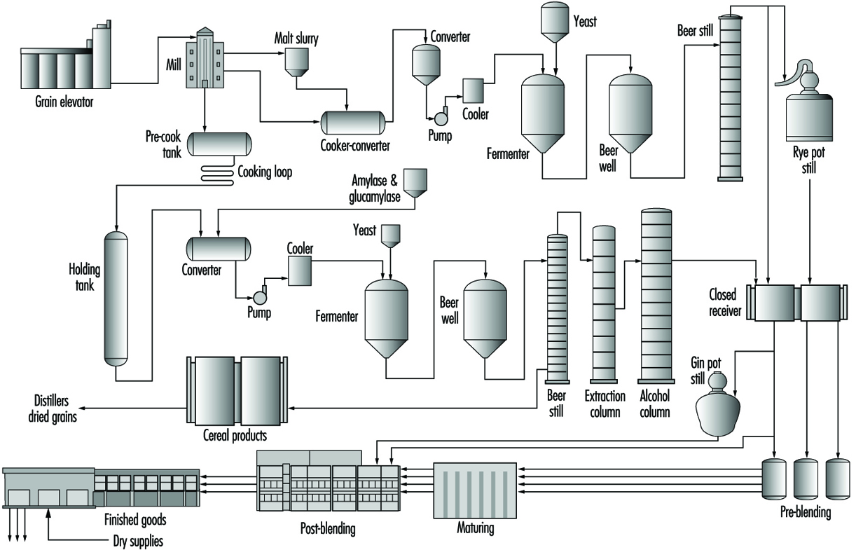
The grain elevator receives and weighs incoming grains and places them in the appropriate bins. Milling consists of grinding the grains necessary for the mash bill. The mash bill is the recipe for the fermentation process.
The cookers receive meal from the mill and slurries with backslop, water and ammonia at a set pH (acidity) and temperature. The starch is solubilized using steam-jet cooking. Enzymes are added to break down starch to smaller starch molecules, reducing mash viscosity. The resulting mash is cooled to fermentation temperature.
Fermentation is the process of converting sugars to alcohol and carbon dioxide by the activities of yeast. Fermenters are cooled to optimum temperature conditions for the yeast, since the reactions that take place are exothermic in nature. Sanitation is important: the biological systems of fermentation are in constant competition with unwanted bacteria that can produce undesirable flavour components.
Distillation type will depend on the spirit being produced. Pot stills are generally used when a particular “character” is required for a product such as cognac and scotches, whereas continuous multicolumn distillation is generally used to produce more neutral spirits which can be used as blenders or neutral grain spirits.
By-product recovery is a very important aspect of the operation of a modern distillery. The residual (fermented and de-alcoholized) grain is rich in protein, vitamins, fibre and fats, and it can be further processed into a valuable animal feed supplement. These processes generally consist of centrifuging, evaporation, drying and mixing.
Whiskies, brandies and rums are aged (matured) in charred oak barrels. Maturation takes place over a number of years to produce the final characteristics that distinguish these products. Once these products have been matured, they are blended and filtered and then packaged as finished products for consumer use.
The bottling room is separated from the rest of the facility, protecting the product from any possible contaminants. The highly automated filling operation requires monitoring for continuous efficiency. Empty bottles are transported by conveyor to the filling machines.
Packaging is the final step prior to warehousing. This process has become automated, although there is a fair amount of manual packing, depending on size of bottle and type of packaging. The packaged product then enters a palletizing machine, which automatically stacks boxes on pallets, which are then removed by fork-lift trucks to warehouses for storage.
Health and Safety Issues
The most obvious safety concern in grain-handling facilities is the threat of dust fires and explosions. High concentrations of grain dust can be explosive; therefore, good housekeeping is the single most important factor in reducing risk of grain dust explosion. Some grains, if damp or kept in storage for a long period, will generate heat, thus becoming a fire hazard. Rotating the grain from bin to bin or adopting a “just-in-time” grain delivery procedure will eliminate this hazard.
Exposure to vapours and gases released throughout the production of distilled spirits is a possible hazard. During the fermentation process, refrigerant gases may cause toxic and explosive risks. Therefore, adequate ventilation and strict maintenance, including the use of intrinsically safe equipment such as air tools, are essential. Particularly significant are the risks of asphyxiation from the vapours of alcohol and carbon dioxide released by the fermentation process, especially when the liquids are transported and decanted into reservoirs, and in confined spaces where ventilation is inadequate. Respirators should be worn by workers in this process. The accompanying box describes some hazards of confined-space entry, which is also discussed elsewhere in this Encyclopaedia.
Hazardous materials such as varsol (mineral spirit), caustics, acids and many other solvents and cleaners are used throughout the facility. Employees must be trained to handle these products safely. A yearly review of a workplace hazardous materials information system, such as the Canadian WHMIS, can provide the opportunity for such ongoing training. Workers must be educated on the use of material data safety sheets (MSDSs), which are information sheets available from suppliers, giving information on the contents of the hazardous product and the related health hazards, emergency action, first aid and so on. It is imperative that every worker who is exposed or likely to be exposed to a hazardous material be trained and then provided with an annual review of the handling of hazardous material. In many countries it is required that MSDSs be available at every location where there are controlled substances and should be made convenient for all workers to access. In addition to employee training, eye wash stations, showers and first aid stations should be made available throughout the plant in order to minimize injury to anyone who is accidentally exposed to a hazardous chemical.
Fork-lift trucks are used in many different processes in the plant. The two most common uses are for transfer of barrels for maturing storage and handling of the finished product. There should be a preventive maintenance programme in place for the fork-lifts as well as a safety programme that ensures that all drivers understand fork-lift safety principles. All drivers should be licenced to operate a fork-lift truck.
The occupational hazards associated with the bottling process are similar to those in most bottling facilities. Repetitive-strain injuries such as tendinitis and carpal tunnel syndrome are the most common injuries, resulting from the repetitive work required for packing bottles and operating labellers. However, the frequency of these occupational injuries has declined; this may be due to the technological changes in the plant that have made jobs less labour intensive, including the automation of packing and the use of computerized equipment.
PPE is common throughout the bottling facility. It is mandatory for bottling room employees to wear safety glasses for eye protection, and ear protection where they are exposed to high noise levels. There should be a safety shoe programme in place, with employees expected to wear steel-toed shoes. If a hazard cannot be eliminated at the source (through engineering) or along the path (through barriers), then PPE must be used for the safety of the worker.
There are many key methods in creating a safe work environment. A company must have a health and safety policy and should convey this via a safety manual that outlines safety procedures. Also, monthly plant inspections can prevent hazards and minimize injuries. Communication with employees regarding safety practices is the most essential part of a successful safety programme.
Confined-space entry hazards in the beverage industry
A confined space is defined as a space in which, because of its construction, location, contents or the work activity therein, the accumulation of a hazardous gas, vapour, dust or fumes, or the creation of an oxygen-deficient atmosphere, may occur. Where confined-space entry could occur, it is imperative that a confined-space entry procedure be in place and that all workers be trained and educated on the procedure. Prior to entering a confined space, testing for oxygen deficiency, combustible gases and toxic gases should be conducted. Positive-pressure self-contained breathing apparatus (SCBA) or other approved respirators may have to be worn by workers during entry. Continuous monitoring is mandatory while personnel are inside the confined space. All personnel entering must be properly suited up with a safety harness, complete with shoulder and leg straps. A stand-by observer must be assigned and maintain constant surveillance of employees within a confined space, and a person adequately trained in artificial respiration must be conveniently available.
The beverage industry has many situations in which there are confined-space entry hazards. Examples of such situations include:
· mixing vats in the soft drink industry in which hazardous vapours or gases might be present
· grain bins in brewing and distilled spirits industries
· fermentation vats in brewing and wine making
· fermenters and stills in the distilled spirits industry.
These grain bins, fermenter tanks and so forth may have to be entered from time to time for cleaning, repairing and so on. During the fermentation process, in particular, there are risks of asphyxiation from the vapours of alcohol and carbon dioxide released by the fermentation process when confined spaces are entered where ventilation is inadequate (Giullemin and Horisberger 1994).
R.G. Aldi and Rita Seguin
Tea Industry
Legend tells us that tea may have been discovered in China by Emperor Shen-Nung, “The Divine Healer”. Observant of the fact that people who drank boiled water enjoyed better health, the wise Emperor insisted on this precaution. When adding branches to the fire, some tea leaves accidentally fell into the boiling water. The Emperor approved of the pleasing aroma and delightful flavour and tea was born.
From China, tea spread throughout Asia, soon becoming the national beverage of China and Japan. It was not until the 1600s that Europe became familiar with the beverage. Shortly thereafter, tea was introduced to North America. In the early 1900s, Thomas Sullivan, a New York wholesaler, decided to package tea in small silk bags rather than in tins. People started brewing the tea in the silk bag rather than removing its contents. Thus the tea bag was first introduced.
Tea is the world’s second most popular drink; only water is consumed more often. Consumers can choose from a wide variety of tea products—instant tea, iced tea mixes, specialty and flavoured teas, herbal teas, ready-to-drink teas decaffeinated teas and tea bags. The packaging of tea products has changed significantly; most of the small shops that once dispensed tea from wooden crates into individual tins have given way to sophisticated high-speed production lines which process, package, and/or bottle thousands of pounds of tea and ready-to-drink mixes per hour.
Process Overview
Production of tea bags consists of the blending of various cut and dried leaf teas from a number of regions around the world. Tea is usually received in wooden crates or large bags. The tea is blended and sent to tea packaging machines, where it is packaged either as individual tea bags or in bulk packages. Instant powdered tea requires blended tea in cut leaf form to be brewed using hot water. The liquid tea concentrate is then spray dried into a fine powder and placed in drums. The tea powder may be sent to the packaging lines where it is packaged into canisters or jars, or blended with other ingredients such as sugar or sugar substitutes. Flavouring such as lemon and other fruit flavors may also be added during the blending stage prior to packaging.
Hazards
There are a number of common safety hazards and health issues associated with the blending, processing and packaging of tea. Safety hazards such as machine guarding, noise, slips and falls and lifting-related injuries are quite common within the beverage industry. Other hazards, such as dust in the blending and packaging areas, are not usually found in wet-process bottling and canning operations.
Machine hazards
The blending and packaging of tea involves equipment and machinery where workers are exposed to chains and sprockets, belts and pullies, rotating shafts and equipment and high-speed packaging lines containing a number of dangerous pinch points. Most injuries are the result of lacerations and bruises to the fingers, hands or arms. Guarding of this equipment is critical to protect workers from getting caught in, under or between moving parts. Guards and/or interlocks should be installed to protect workers from moving parts where the potential of injury exists. Whenever a guard is removed (such as for maintenance), all energy sources should be isolated and maintenance and repair of equipment should be with an effective lockout/tagout programme in effect.
Dust hazards
Tea dust can be present in blending and packaging operations. Tea dust may also be present in high concentrations during clean-up or blow-down operations. Tea dust with a diameter greater than 10 micrometers can be classified as “nuisance dust”. Nuisance dust has little adverse effect on the lungs and should not produce significant organic disease or toxic effects when exposures are kept under reasonable control. Excessive concentrations of nuisance dust in the workroom air, however, may cause unpleasant deposits in the eyes, ears and nasal passages. Once inhaled, these particles may become entrapped in the nasal and pharyngeal region of the respiratory system, until they are expelled through the body’s own cleaning mechanisms (e.g., coughing or sneezing).
Respirable dust particulates are those that are less than 10 micro-meters in diameter and therefore small enough to pass through the nasal and pharyngeal regions and enter the lower respiratory tract. Once in the lungs, they may become embedded in the alveolar region, where scar tissue could develop. Respirable particulates can be respiratory irritants, especially in asthmatics. Effective seals and closures will help contain dust particles.
Exhaust ventilation or other types of dust-control equipment should be provided at the site of dust production to maintain dust levels below generally recognized standards (10 mg/m3) or other government regulations that may apply. Dust masks should be worn by workers who may be highly sensitive to dusts and by workers exposed to large concentrations of dust at any one time. Persons with chronic bronchitis or asthma are at higher risk. Workers who suffer from hypersensitivity to tea dust should be removed from the area.
Although there is little information on actual tea dust explosions, test data indicate that the explosion characteristics of tea dust are relatively weak. It appears that the greatest potential for a tea dust explosion exists with storage bins and dust collectors where concentrations and particle size are optimized. Minimizing dust concentration within a room or process will reduce the potential of a dust explosion. Electrical equipment designed for dust hazard areas may also be desirable in some operations.
Although tea and tea dust may not always burst into flames, large quantities of tea will almost always smoulder if ignited. Large quantities of water in a fine mist can be used to cool the smouldering tea below its ignition temperature.
Noise
As in most high-speed packaging operations, high noise levels are almost always present in the tea industry. High noise levels can be generated from vibrating blenders, air-operated and other packaging machines, air conveying systems, dust collectors and box cutters. The noise levels in many of these areas can range from 85 dBA to over 90 dBA. The major potential health hazard associated with exposure to noise lies in the possibility of producing permanent hearing loss. The severity of hearing loss is dependent on the noise levels within the workplace, duration of the exposure and the individual’s personal susceptibility. Noise and hearing conservation programmes are discussed further elsewhere in this Encyclopaedia.
Chemical hazards
Although most of the production processes and packaging operations do not expose workers to hazardous chemicals, sanitation operations use chemicals to clean and sanitize equipment. Some cleaning chemicals are handled in bulk quantities through fixed pipe systems, while other chemicals are applied by hand using predetermined mixtures. Exposure to these chemicals can cause respiratory problems, dermatitis or skin irritation and chemical burns to the skin. Severe burns to the eyes and/or loss of vision are also hazards associated with the handling of cleaning chemicals. Proper evaluations as to the hazards of the chemicals being used are essential. Proper selection and use of PPE should be part of routine job procedure. PPE such as splash-proof goggles or face shields, chemical-resistant gloves, aprons, boots and a respirator should be considered. Emergency eye and body wash stations should be provided where hazardous chemicals are either stored, mixed or used.
Material handling
Tea arrives on pallets in either bags or crates and is stored in warehouses to await blending and packaging. These bags and crates are moved either by hand or by material-handling devices such as fork-lifts or vacuum lifts. Once blended, the tea is conveyed to hoppers for packaging. Packaging operations can vary from using highly automated equipment to labour-intensive hand packaging operations (figure 1). Injuries to the lower back resulting from lifting tasks are quite common when handling bags weighing 100 pounds (45.5 kg) or more. Repetitive motions on packaging lines can result in cumulative trauma to the wrist, arm and/or shoulder area.
Figure 1. Packing of tea at the Brooke Bond tea and coffee factory in Dar-es-Salaam, Tanzania.

Mechanical devices such as vacuum lifts can aid in reducing heavy lifting tasks. Assigning two workers to a heavy lifting task can help reduce the chances of a serious back injury. Modifying work stations to be more ergonomically correct and/or automating equipment on packaging lines can reduce worker exposure to repetitive tasks. Rotating workers to light duty tasks can also reduce worker exposure to such tasks.
Personal aids such as back belts and wrist bands are also used by some workers to assist them in their lifting tasks or for temporary relief of minor strains. However, these have not been shown to be effective, and they may even be harmful.
Most warehouse operations require the use of fork-lift trucks. Failure to drive at safe speeds, sharp turns, driving with raised forks, failure to observe or yield to pedestrians and loading/ unloading accidents are the leading causes of injuries involving fork-lift operators. Only trained and competent operators should be permitted to drive fork-lifts. Training should consist of formal classroom training and a driving test where operators can demonstrate their skills. Proper maintenance and daily pre-use inspections also help ensure the safe operation of these vehicles.
Slips, trips and falls
Slips, trips and falls are a major concern. In dry blending and packaging operations, fine tea dust will accumulate on walking and working surfaces. Good housekeeping is important. Floors should be swept clean of tea dust on a regular basis. Debris and other items left on the floor should be picked up immediately. Slip-resistant, rubber-soled shoes appear to provide the best traction. Wet-process areas also provide slip and fall hazards. Floors should be kept as dry as possible. Adequate floor drainage should be provided within all wet-process areas. Standing water should not be permitted to accumulate. Where standing water exists, it should be mopped into floor drains.
Exposure to high temperatures
Contact with hot water, steam lines and process equipment can result in serious injury from burns. Most burns occur on the hands, arms and face. Hot water used for clean-up or wash-down has also been known to cause burns on feet and legs.
Heat sealers and glue operations on packaging lines also can cause burns. Guarding of exposed hot points on equipment is important. The proper evaluation of the hazards, and selection and use of personal protective equipment, will also help reduce or eliminate worker exposure to high temperatures and burns. Use of pipeline breaking and lockout procedures will protect workers from the unexpected release of hot liquids and steam.
Safe Practices
A general safety programme which addresses the use and selection of PPE, entry into confined spaces, isolation of energy sources, identification and communication of hazardous chemicals, self-inspection programmes, hearing conservation programmes, the control of infectious materials, process management and emergency response programmes should also be included as part of the work process. Training of workers in safe work practices is important in reducing worker exposure to hazardous conditions and injuries.
More...
Coffee Industry
General Overview
Coffee as a beverage was introduced in Europe during the sixteenth century, first in Germany and then throughout the European continent during the following century, especially to France and Holland. Afterwards, it spread to the rest of the world.
Since coffee will not keep its characteristic smell and flavour for long, after roasting and grinding, industrial establishments to roast and grind coffee have become needed wherever coffee is consumed. The establishments are usually small or medium-sized plants, but large factories do exist, mainly to produce regular as well as instant (soluble) coffee.
It is difficult to estimate the number of workers employed by the coffee industry. Some of the smaller plants do not keep registries, and figures are not entirely reliable. Considering a total consumption of approximately 100 million 60 kg bags of coffee during the year 1995, the worldwide coffee trade represents about US$50 million. Table 1 lists selected coffee-importing countries, giving an idea of the present world consumption.
Table 1. Selected coffee importers (in tonnes).
|
Country |
1990 |
1991 |
1992 |
|
United States |
1,186,244 |
1,145,916 |
1,311,986 |
|
France |
349,306 |
364,214 |
368,370 |
|
Japan |
293,969 |
302,955 |
295,502 |
|
Spain |
177,681 |
176,344 |
185,601 |
|
United Kingdom |
129,924 |
119,020 |
128,702 |
|
Austria |
108,797 |
118,935 |
125,245 |
|
Canada |
120,955 |
126,165 |
117,897 |
Source: FAO 1992.
Coffee manufacturing is a relatively simple process, including cleaning, roasting, grinding and packing processes, as shown in figure 1. However, modern technology has led to complex processes, with an increase in speed of production and requiring laboratories for quality-control testing of the product.
Figure 1. Flow chart of coffee manufacturing.
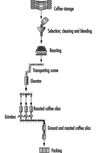
Coffee beans arrive at factories in 60 kg bags, which are unloaded mechanically or manually. In the latter case, usually two workers hold a bag and place it upon another worker’s head. This worker will carry the bag to be stored. Even when transportation is done on coveyor belts, some physical effort with high energy consumption is required.
The use of instant coffee has steadily increased, reaching approximately 20% of the world consumption. Instant coffee is obtained through a complex process in which blasts of hot air blow over coffee extracts, followed by evaporation, cooling and lyophilization (freeze drying), varying in details from one factory to another. In the manufacture of decaffeinated coffee, which represents over 10% of the consumption in the United States and in Europe, some plants still utilize chlorinated solvents (such as methylene chloride), which is removed by a blast of water vapour.
Potential Risks and Health Effects
To start coffee processing, bags are opened with a small knife, and the beans are thrown inside a bin to be cleaned. The work area is noisy and a large amount of residual particulate material remains in suspension, released from the cleaning machine.
Roasting exposes workers to risks of burns and thermal discomfort. Bean mixing, or blending, is done automatically, as is grinding, in areas which may be deficient in lighting due to interference from suspended coffee dust. Dirt may accumulate, noise levels may be high and mechanization requires work at a high speed.
After grinding, bags of different materials and sizes are filled and then packed, usually in cardboard boxes. When performed manually, these operations require high-speed repetitive motion of hands and arms. Cardboard boxes are transported to storage areas and then to their final destination.
The strong odour characteristic of the coffee industry may bother workers inside the plants, and the surrounding community as well. The significance of this problem as a potential health risk has not yet been clarified. The odour of coffee is due to a mixture of different products; research is ongoing to identify individual effects of these chemicals. Some components of the coffee dust and some of the odour-producing substances are known to be allergens.
Potential risks in instant-coffee plants are similar to those in regular coffee production; in addition, there are risks due to hot steam and boiler explosions. In the removal of caffeine, even when performed automatically, the risk of solvent exposure may be present.
Other potential risks which may affect workers’ health are similar to those found in food industries in general. Risks for accidents arise from cuts from knives used in bag opening, burns during roasting and crushing during grinding operations, especially in old machinery without automatic machine guarding. There are fire and explosion hazards from the large amounts of dust, unsafe electric wiring and gas used for heating the roasters.
Several hazards may be found in the coffee industry including, among others: hearing loss due to excessive noise, thermal stress during roasting, poisoning from pesticides and musculoskeletal disorders, especially affecting the backs of workers who lift and carry heavy bags.
Allergic disorders affecting the eye, skin or respiratory system may occur in any area in a coffee plant. It is the coffee dust which is associated with bronchitis with lung function impairment; rhinitis and conjunctivitis are also concerns (Sekimpi et al. 1996). Allergic reactions to contaminants of bags previously used for other materials, such as castor bean seeds, have also occurred (Romano et al. 1995).
Repetitive-motion disorders may result from high-speed motion in packing operations, especially where workers are not warned of the risk.
In less developed countries, effects of occupational risks may develop early because conditions of work may be inadequate and, moreover, other social and public health factors may contribute to disease. Such factors include: low salaries, inadequate medical care and social security, improper housing and sanitation, low levels of education, illiteracy, endemic diseases and malnutrition.
Preventive Measures
Machine guarding, general ventilation and local exhaust systems, noise abatement, housekeeping and cleaning, decreased bag weights, substitutes of solvents used in caffeine extraction, periodic inspection and preventive maintenance of boilers are examples of preventive measures that are required for ensuring adequate levels of industrial hygiene and safety. Odour intensity may be reduced through modification of roasting procedures. The organization of work can be modified so that repetitive-motion disorders may be avoided through alteration of working position and rhythm, as well as the introduction of systematic breaks and regular exercises, among other practices.
Periodic health screening should stress evaluation of exposure to herbicides and pesticides, spinal disorders and early signs of repetitive-motion disorders. Scratch tests using extracts from coffee beans, even if not universally accepted as completely reliable, may be useful in the identification of hypersusceptible individuals. Lung function tests may aid in the early diagnosis of obstructive respiratory conditions.
Health education is an important instrument to enable workers to identify health risks and their consequences and to become aware of their right to a healthy working environment.
Governmental action is required, through legislation and enforcement; employers’ participation is needed in providing and maintaining adequate working conditions.
Soft Drink Bottling and Canning
In most established markets around the world, soft drinks now rank first among manufactured beverages, surpassing even milk and coffee in terms of per capita consumption.
Including ready-to-drink, packaged products and bulk mixes for fountain dispensing, soft drinks are available in almost every conceivable size and flavour and in virtually every channel of retail distribution. Complementing this universal availability, much of the soft drink category’s growth can be attributed to convenient packaging. As consumers have become increasingly mobile, they have opted for easier-to-carry packaged goods. With the advent of the aluminium can and, more recently, the resealable plastic bottle, soft drink packaging has become lighter and more portable.
Stringent quality-control standards and state-of-the-art water treatment processes also have afforded the soft drink industry a high degree of confidence regarding product purity. Moreover, the manufacturing or bottling plants that produce soft drinks have evolved into highly mechanized, efficient and spotlessly clean food-processing facilities.
As early as the 1960s, most bottlers were producing beverages through machinery that ran at 150 bottles per minute. As product demand has continued to skyrocket, soft drink manufacturers have shifted to faster machinery. Thanks to advances in production technology, filling lines now are able to run in excess of 1,200 containers per minute, with minimal downtime except for product or flavour changes. This highly automated environment has allowed soft drink manufacturers to reduce the number of employees required to operate the lines (see figure 1). Still, as production efficiencies have risen dramatically, plant safety has remained an ever-important consideration.
Figure 1. Control panel in an automated soft drink plant in Novosibirsk, Russia.
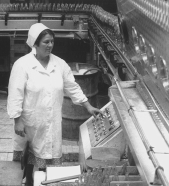
Soft drink bottling or manufacturing involves five major processes, each with its own safety issues that must be evaluated and controlled:
- treating water
- compounding ingredients
- carbonating product
- filling product
- packaging.
See figure 2.
Figure 2. Flow chart of basic bottling operations.

Soft drink manufacturing starts with water, which is treated and cleansed to meet exacting quality-control standards, usually exceeding the quality of the local water supply. This process is critical to achieving high product quality and consistent taste profiles.
As ingredients are being compounded, the treated water is piped into large, stainless-steel tanks. This is the stage at which various ingredients are added and mixed. Diet beverages are mixed with artificial, non-nutritive sweeteners such as aspartame or saccharin, whereas regularly sweetened drinks typically use liquid sugars like fructose or sucrose. It is during this stage of the production process that food colouring may be added. Flavoured, sparkling waters receive the desired flavouring at this stage, while plain waters are stored in the mixing tanks until the filling line calls for them. It is common for bottling companies to purchase concentrate from other firms.
In order for carbonation (absorption of carbon dioxide (CO2)) to occur, soft drinks are cooled using large, ammonia-based refrigeration systems. This is what gives carbonated products their effervescence and texture. CO2 is stored in a liquid state and piped into carbonation units as needed. This process can be manipulated to control the required rate of beverage absorption. Depending upon the product, soft drinks may contain from 15 to 75 psi of CO2. Fruit-flavoured soft drinks tend to have less carbonation than colas or sparkling water. Once carbonated, the product is ready to be dispensed into bottles and cans.
The filling room usually is separated from the rest of the facility, protecting open product from any possible contaminants. Again, the highly automated filling operation requires a minimal number of personnel. See figure 3 . Filling room operators monitor the equipment for efficiency, adding bulk lids or caps to the capping operation as necessary. Empty bottles and cans are transported automatically to the filling machine via bulk material-handling equipment.
Figure 3. Soft drink canning line showing filling operations.
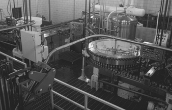
Stringent quality-control procedures are followed throughout the production process. Technicians measure many variables, including CO2, sugar content and taste, to ensure that finished drinks meet required quality standards.
Packaging is the last stage prior to warehousing and delivery. This process also has become highly automated. Meeting various marketplace requirements, bottles or cans enter the packaging machinery and may be wrapped with cardboard to form cases or placed into reusable plastic trays or shells. The packaged products then enter a palletizing machine, which automatically stacks them onto pallets. (See figure 4.) Next, the loaded pallets are moved—typically via fork-lift—to a warehouse, where they are stored.
Figure 4. Eight-packs of 2-litre soft drink plastic bottles on the way to an automatic palletizer.
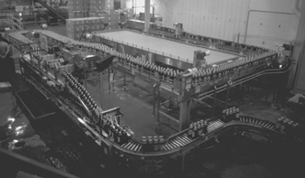
Hazard Prevention
Lifting-related injuries—especially to employees’ backs and shoulders—are not uncommon in the beverage business. While many technological advances have been made in material handling over the years, the industry continues to seek safer, more efficient ways to move heavy product.
Certainly, employees must be provided with the proper training on safe work practices. Injuries also can be minimized by limiting exposure to lifting through enhanced work-station design. Adjustable tables can be used to raise or lower material to waist level, for example, so that employees do not have to bend and lift as much. In this manner, most weight-related stress is transferred to a piece of equipment instead of the human body. All beverage manufacturers should implement ergonomics programmes that identify work-related hazards and minimize the risks—either through modification or by developing better equipment. A reasonable means to that end is job rotation, which reduces employee exposure to high-risk tasks.
The use of machine guarding is another critical component of safe beverage manufacturing. Equipment such as fillers and conveyors move at high speeds and, if left unguarded, could snag employee clothing or body parts, causing potentially severe injuries. Conveyors, pulleys, gears and spindles must have appropriate covers to prevent employee contact. Overhead conveyors can create an additional hazard of falling cases. Netting or wire-mesh screens should be installed to protect against this danger. Maintenance programmes should dictate that all guarding which is removed for repair be replaced as soon as repair work is completed.
Since wet conditions are prevalent in the filling room, adequate drainage is necessary to keep liquid from accumulating on nearby walkways. In order to avoid slip-and-fall injuries, proper efforts must be made to keep floors as dry as possible. While steel-toed shoes usually are not required in the filling room, slip-resistant soles are highly recommended. Shoes should be selected based on the slip coefficient of the sole. Additionally, all electrical equipment should be properly grounded and protected from any moisture. Employees must take precautions to dry the areas around equipment before any electrical work begins.
Good housekeeping practices and routine inspections also are beneficial in keeping the workplace hazard-free. By taking these comparatively simple steps, management can be sure that all equipment is in good operating condition and properly stored. Emergency equipment such as fire extinguishers and eyewash stations also should be inspected for proper operation.
Although most of the chemicals present in bottling plants are not extremely hazardous, every operation uses flammable substances, acids, caustics, corrosives and oxidants. Appropriate work practices should be developed so employees know how to work safely with these chemicals. They must be taught how properly to store, handle and dispose of the chemicals and how to wear protective gear. Training should cover the location and operation of emergency response equipment. Eyewash stations and showers can minimize injury to anyone who is accidentally exposed to a hazardous chemical.
It also is necessary to install equipment such as chemical booms and dykes, as well as absorbent material, to be used in the event of a spill. Properly designed hazardous chemical storage facilities will minimize the risk of employee injury, too. Flammables should be separated from corrosives and oxidants.
The large tanks used for mixing ingredients, which need to be entered and cleaned routinely, are considered confined spaces. See the box on confined spaces in this chapter for information on the related hazards and precautions.
Mechanized equipment has become increasingly complex, often controlled by remote computers, pneumatic lines or even gravity. Employees must be sure that this equipment has been de-energized before it is serviced. Proper de-energizing procedures must be developed to guarantee the safety of those who maintain and repair this equipment. Energy must be shut off and locked out at its source so that the unit being serviced cannot be accidentally energized, causing potentially fatal injuries to service employees or nearby line operators.
Safety training and written de-energizing procedures are critical for each piece of equipment. Emergency stop switches should be strategically placed on all equipment. Interlocked safety devices are used to stop the equipment automatically when doors are opened or light beams are interrupted. Employees must be informed, however, that these devices cannot be relied upon to completely de-energize the equipment, but only to stop it in an emergency. Emergency stop switches cannot take the place of a proven de-energizing procedure for equipment maintenance.
Chlorine, which is used in the water treatment area, could be hazardous in the event of an accidental release. Chlorine typically comes in steel cylinders, which should be stored in an isolated, well-ventilated area and secured from tipping. Employees should be trained to follow safe cylinder-changing procedures. They also should be taught how to take quick, decisive action if an accidental release of chlorine occurs. In the late 1990s new chlorine compounds are gradually replacing the need for chlorine gas. Although still hazardous, these compounds are much safer to handle than gas.
Ammonia is used as a refrigerant in bottling operations. Typically, large ammonia systems can create a health hazard in the event of a leak or a spill. Bottling facilities should develop emergency response procedures to identify the responsibilities of involved employees. Those who are required to respond to such an emergency must be trained in spill response and respirator use. In the event of a leak or spill, respirators should be immediately available, and all non-essential personnel evacuated to safe areas until the situation is controlled.
CO2, which is used in the filling operation, also can create health concerns. If filling rooms and adjacent work areas are not adequately ventilated, CO2 accumulation can displace oxygen in employees’ breathing zones. Facilities should be monitored regularly for elevated CO2 levels and, if they are detected, ventilation systems should be inspected to determine the cause for this occurence. Additional ventilation may be required to correct the situation.
Technological advances have made available better sound-absorption material for insulating or muffling motors and gears in most equipment. Still, given the function and size of filling equipment, noise levels generally exceed 90 dBA in this area. Employees who are exposed to this level of noise for an 8-hour weighted average must be protected. Good hearing protection programmes should include research on better ways to control noise; employee education on related health effects; personal noise protection; and training on how to use hearing protection devices, the wearing of which must be enforced in high-noise areas. Employee hearing must be routinely checked.
Fork-lifts are operated throughout the bottling plant and their safe use is imperative. In addition to demonstrating their driving skills, potential operators must understand fork-lift safety principles. Licenses are commonly issued to show that a minimum level of competency has been achieved. Fork-lift safety programmes should include a pre-use inspection process, whereby the vehicles are checked to ensure that all safety equipment is in place and working. Any deficient conditions should be immediately reported and corrected. Gas or liquid petroleum (LP) fork-lifts generate carbon monoxide as a by-product of combustion. Such emissions can be minimized by keeping the fork-lift engines tuned to manufacturers’ specifications.
Personal protective equipment (PPE) is common throughout the bottling facility. Filling-room employees wear eye and ear protection. Sanitation crews wear face, hand and foot protection that is appropriate for the chemicals they are exposed to. While slip-resistant shoes are recommended throughout the plant, maintenance employees should also have the added protection of steel-toed shoes. The key to a good PPE programme is to identify and evaluate the potential hazards associated with each job and to determine whether those hazards can be eliminated through engineering changes. If not, PPE must be selected to address the specific hazard at hand.
Management’s role is critical in identifying hazards and developing practices and procedures to minimize them in the workplace. Once developed, these practices and procedures must be communicated to employees so that they can perform their jobs safely.
As plant technology continues to advance—providing better equipment, new guards and protective devices—soft drink bottlers will have even more ways to maintain the safety of their workforce.
Soft Drink Concentrate Manufacturing
Process Overview
The making of the concentrate is the first step in the production of a carbonated soft drink. At the beginnings of the industry, in the nineteenth century, both concentrate and soft drink were manufactured in the same facility. Sometimes the concentrate was sold to the consumers, who would make their own soft drinks. As the carbonated soft drink business has grown, the concentrate and the soft drink manufacturing have become specialized. Today, a concentrate manufacturing plant sells its product to various bottling companies.
Concentrate plants are constantly optimizing their operation through systems automation. As the demand for concentrate increases, automation has allowed the manufacturer to satisfy the demand without expanding the size of the manufacturing plant. Packaging size has increased too. Early in the industry, 1/2-, 1- and 5-gallon containers were the most common. Today 40- and 50-gallon drums and even tank trucks with capacities of 3,000 to 4,000 gallons are used.
Operations in a concentrate manufacturing plant can be divided into five basic processes:
- treating water
- receiving raw materials
- concentrate manufacturing
- concentrate and additives filling
- shipping finished products.
Each of these processes has safety hazards that must be evaluated and controlled. Water is a very important ingredient in the concentrate and it must have excellent quality. Each concentrate plant treats water until it reaches the desired quality and is free from micro-organisms. Water treatment is monitored during all stages.
When the plant receives the compounding ingredients, inspection, sampling and analysing of the ingredients in the quality-control department are begun. Only materials that have passed the tests will be used in the concentrate manufacturing process. Some of the raw materials are received in tank trucks and require special handling. Also, packaging material is received, evaluated and analysed in the same way as the raw materials.
During the manufacturing of concentrate, treated water and liquid and solid ingredients are pumped into stainless-steel tanks, where they are mixed, homogenized and/or extracted in accordance with the manufacturing instructions. The tanks have capacities of 50 gallons, 10,000 gallons and even more. These tanks are completely clean and sanitized at the time of mixing.
Once the concentrate is manufactured, the filling stage is started. All the products are piped into the filling room. Filling machines are strictly cleaned and sanitized before the filling process starts. Most of the filling machines are dedicated to specific container sizes. The product is kept inside pipes and tanks at times during the filling process in order to avoid contamination. Each container should be labelled with the product name and handling hazards (if necessary). Full containers are moved by conveyors to the packaging area. Containers are placed on pallets and wrapped in plastic or tied before they are stored. Besides the concentrates, additives to be used in the preparation of carbonated soft drinks are packed. Many of these additives are packed in plastic bags and placed in boxes.
Once at the warehouse, the products are divided and prepared to be sent to the different bottling companies. These products should be labelled following all government regulations. If products are going to another country, the product must be labelled in accordance with the other country’s labelling requirements.
Production of fruit juices
Fruit juices are made from a wide variety of fruits, including oranges and other citrus fruits, apples, grapes, cranberries, pineapples, mangoes and so forth. In many cases, various fruit juices are blended. Usually, the fruit is processed into a concentrate near where it is grown, then shipped to a fruit juice packager. Fruit juices can be sold as concentrates, frozen concentrates (especially orange juice) and as the diluted juice. Often sugar and preservatives are added.
Once received at the processing plant, the oranges are washed, graded to remove damaged fruit, separated according to size and sent to the juice extractors. There the oils are extracted from the peel, and then the juice extracted by crushing. The pulpy juice is screened to remove seeds and pulp, which often end up as cattle feed. If the orange juice is intended for sale as “not from concentrate”, it is then pasteurized. Otherwise the juice is sent to evaporators, which remove most of the water by heat and vacuum, then chilled, to produce the frozen, concentrated orange juice. This process also removes many oils and essences which are blended back into the concentrate before shipping to the juice packager.
The frozen concentrate is shipped to the packager in refrigerated trucks or tankers. Many dairies package orange juice using the same equipment used to package milk. (See the article “Dairy products industry” elsewhere in this volume.) The concentrate is diluted with filtered water, pasteurized and packaged under sterile conditions. Depending on the amount of water added, the final product can be cans of frozen orange juice concentrate or ready-to-serve orange juice.
Michael McCann
Hazard Prevention
Hazards in a concentrate manufacturing plant vary depending on the products manufactured and the size of the plant.
Concentrate plants have a low injury rate due to a high degree of automation and mechanized handling. Materials are handled by fork-lifts, and full containers are placed on pallets by automatic palletizers. Although, employees generally do not have to use excessive force to get the job done, lifting related injuries remain a concern. Major hazards include engines and equipment in motion, objects falling from overhead containers, energy hazards in repair and maintenance, confined space hazards in cleaning mixing tanks, noise, fork-lift accidents and hazardous chemical cleaning agents. See the article “Soft drink bottling and canning” for more information on hazards and precautions.
Production of Fruit Juices
Fruit juices are made from a wide variety of fruits, including oranges and other citrus fruits, apples, grapes, cranberries, pineapples, mangoes and so forth. In many cases, various fruit juices are blended. Usually, the fruit is processed into a concentrate near where it is grown, then shipped to a fruit juice packager. Fruit juices can be sold as concentrates, frozen concentrates (especially orange juice) and as the diluted juice. Often sugar and preservatives are added.
Once received at the processing plant, the oranges are washed, graded to remove damaged fruit, separated according to size and sent to the juice extractors. There the oils are extracted from the peel, and then the juice extracted by crushing. The pulpy juice is screened to remove seeds and pulp, which often end up as cattle feed. If the orange juice is intended for sale as “not from concentrate”, it is then pasteurized. Otherwise the juice is sent to evaporators, which remove most of the water by heat and vacuum, then chilled, to produce the frozen, concentrated orange juice. This process also removes many oils and essences which are blended back into the concentrate before shipping to the juice packager.
The frozen concentrate is shipped to the packager in refrigerated trucks or tankers. Many dairies package orange juice using the same equipment used to package milk. (See the article “Dairy products industry” elsewhere in this volume.) The concentrate is diluted with filtered water, pasteurized and packaged under sterile conditions. Depending on the amount of water added, the final product can be cans of frozen orange juice concentrate or ready-to-serve orange juice.
" DISCLAIMER: The ILO does not take responsibility for content presented on this web portal that is presented in any language other than English, which is the language used for the initial production and peer-review of original content. Certain statistics have not been updated since the production of the 4th edition of the Encyclopaedia (1998)."