- You are here:
-
Home

-
Part XVI. Construction
-
Construction
- Tools, Equipment and Materials
Fatigue and Recovery
Fatigue and recovery are periodic processes in every living organism. Fatigue can be described as a state which is characterized by a feeling of tiredness combined with a reduction or undesired variation in the performance of the activity (Rohmert 1973).
Not all the functions of the human organism become tired as a result of use. Even when asleep, for example, we breathe and our heart is pumping without pause. Obviously, the basic functions of breathing and heart activity are possible throughout life without fatigue and without pauses for recovery.
On the other hand, we find after fairly prolonged heavy work that there is a reduction in capacity—which we call fatigue. This does not apply to muscular activity alone. The sensory organs or the nerve centres also become tired. It is, however, the aim of every cell to balance out the capacity lost by its activity, a process which we call recovery.
Stress, Strain, Fatigue and Recovery
The concepts of fatigue and recovery at human work is closely related to the ergonomic concepts of stress and strain (Rohmert 1984) (figure 1).
Figure 1. Stress, strain and fatigue
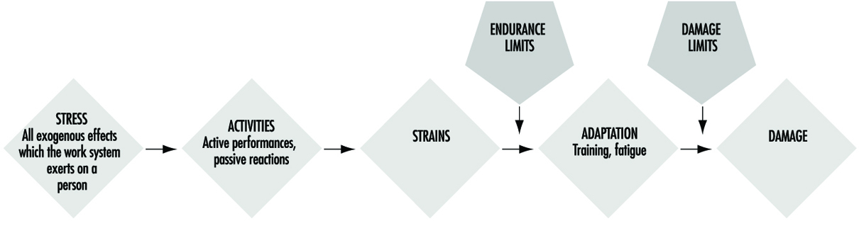
Stress means the sum of all parameters of work in the working system influencing people at work, which are perceived or sensed mainly over the receptor system or which put demands on the effector system. The parameters of stress result from the work task (muscular work, non-muscular work—task-oriented dimensions and factors) and from the physical, chemical and social conditions under which the work has to be done (noise, climate, illumination, vibration, shift work, etc.—situation-oriented dimensions and factors).
The intensity/difficulty, the duration and the composition (i.e., the simultaneous and successive distribution of these specific demands) of the stress factors results in combined stress, which all the exogenous effects of a working system exert on the working person. This combined stress can be actively coped with or passively put up with, specifically depending on the behaviour of the working person. The active case will involve activities directed towards the efficiency of the working system, while the passive case will induce reactions (voluntary or involuntary), which are mainly concerned with minimizing stress. The relation between the stress and activity is decisively influenced by the individual characteristics and needs of the working person. The main factors of influence are those that determine performance and are related to motivation and concentration and those related to disposition, which can be referred to as abilities and skills.
The stresses relevant to behaviour, which are manifest in certain activities, cause individually different strains. The strains can be indicated by the reaction of physiological or biochemical indicators (e.g., raising the heart rate) or it can be perceived. Thus, the strains are susceptible to “psycho-physical scaling”, which estimates the strain as experienced by the working person. In a behavioural approach, the existence of strain can also be derived from an activity analysis. The intensity with which indicators of strain (physiological-biochemical, behaviouristic or psycho-physical) react depends on the intensity, duration, and combination of stress factors as well as on the individual characteristics, abilities, skills, and needs of the working person.
Despite constant stresses the indicators derived from the fields of activity, performance and strain may vary over time (temporal effect). Such temporal variations are to be interpreted as processes of adaptation by the organic systems. The positive effects cause a reduction of strain/improvement of activity or performance (e.g., through training). In the negative case, however, they will result in increased strain/reduced activity or performance (e.g., fatigue, monotony).
The positive effects may come into action if the available abilities and skills are improved in the working process itself, e.g., when the threshold of training stimulation is slightly exceeded. The negative effects are likely to appear if so-called endurance limits (Rohmert 1984) are exceeded in the course of the working process. This fatigue leads to a reduction of physiological and psychological functions, which can be compensated by recovery.
To restore the original performance rest allowances or at least periods with less stress are necessary (Luczak 1993).
When the process of adaptation is carried beyond defined thresholds, the employed organic system may be damaged so as to cause a partial or total deficiency of its functions. An irreversible reduction of functions may appear when stress is far too high (acute damage) or when recovery is impossible for a longer time (chronic damage). A typical example of such damage is noise-induced hearing loss.
Models of Fatigue
Fatigue can be many-sided, depending on the form and combi-nation of strain, and a general definition of it is yet not possible. The biological proceedings of fatigue are in general not measurable in a direct way, so that the definitions are mainly oriented towards the fatigue symptoms. These fatigue symptoms can be divided, for example, into the following three categories.
- Physiological symptoms: fatigue is interpreted as a decrease of functions of organs or of the whole organism. It results in physiological reactions, e.g., in an increase of heart rate frequency or electrical muscle activity (Laurig 1970).
- Behavioural symptoms: fatigue is interpreted mainly as a decrease of performance parameters. Examples are increasing errors when solving certain tasks, or an increasing variability of performance.
- Psycho-physical symptoms: fatigue is interpreted as an increase of the feeling of exertion and deterioration of sensation, depending on the intensity, duration and composition of stress factors.
In the process of fatigue all three of these symptoms may play a role, but they may appear at different points in time.
Physiological reactions in organic systems, particularly those involved in the work, may appear first. Later on, the feelings of exertion may be affected. Changes in performance are manifested generally in a decreasing regularity of work or in an increasing quantity of errors, although the mean of the performance may not yet be affected. On the contrary, with appropriate motivation, the working person may even try to maintain performance through will-power. The next step may be a clear reduction of performance ending with a breakdown of performance. The physiological symptoms may lead to a breakdown of the organism including changes of the structure of personality and in exhaustion. The process of fatigue is explained in the theory of successive destabilization (Luczak 1983).
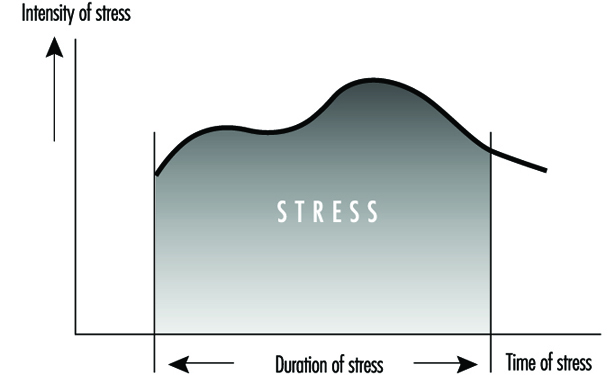
The principal trend of fatigue and recovery is shown in figure 2.
Figure 2. Principal trend of fatigue and recovery

Prognosis of Fatigue and Recovery
In the field of ergonomics there is a special interest in predicting fatigue dependent on the intensity, duration and composition of stress factors and to determine the necessary recovery time. Table 1 shows those different activity levels and consideration periods and possible reasons of fatigue and different possibilities of recovery.
Table 1. Fatigue and recovery dependent on activity levels
|
Level of activity |
Period |
Fatigue from |
Recovery by |
|
Work life |
Decades |
Overexertion for |
Retirement |
|
Phases of work life |
Years |
Overexertion for |
Holidays |
|
Sequences of |
Months/weeks |
Unfavourable shift |
Weekend, free |
|
One work shift |
One day |
Stress above |
Free time, rest |
|
Tasks |
Hours |
Stress above |
Rest period |
|
Part of a task |
Minutes |
Stress above |
Change of stress |
In ergonomic analysis of stress and fatigue for determining the necessary recovery time, considering the period of one working day is the most important. The methods of such analyses start with the determination of the different stress factors as a function of time (Laurig 1992) (figure 3).
Figure 3. Stress as a function of time
The stress factors are determined from the specific work content and from the conditions of work. Work content could be the production of force (e.g., when handling loads), the coordination of motor and sensory functions (e.g., when assembling or crane operating), the conversion of information into reaction (e.g., when controlling), the transformations from input to output information (e.g., when programming, translating) and the production of information (e.g., when designing, problem solving). The conditions of work include physical (e.g., noise, vibration, heat), chemical (chemical agents) and social (e.g., colleagues, shift work) aspects.
In the easiest case there will be a single important stress factor while the others can be neglected. In those cases, especially when the stress factors results from muscular work, it is often possible to calculate the necessary rest allowances, because the basic concepts are known.
For example, the sufficient rest allowance in static muscle work depends on the force and duration of muscular contraction as in an exponential function linked by multiplication according to the formula:
![]()
with
R.A. = Rest allowance in percentage of t
t = duration of contraction (working period) in minutes
T = maximal possible duration of contraction in minutes
f = the force needed for the static force and
F = maximal force.
The connection between force, holding time and rest allowances is shown in figure 4.
Figure 4. Percentage rest allowances for various combinations of holding forces and time
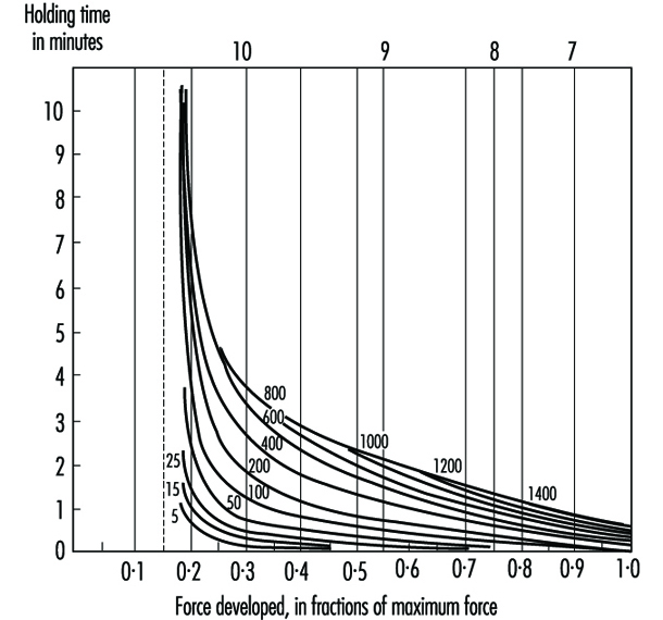
Similar laws exist for heavy dynamic muscular work (Rohmert 1962), active light muscular work (Laurig 1974) or different industrial muscular work (Schmidtke 1971). More rarely you find comparable laws for non-physical work, e.g., for computing (Schmidtke 1965). An overview of existing methods for determining rest allowances for mainly isolated muscle and non-muscle work is given by Laurig (1981) and Luczak (1982).
More difficult is the situation where a combination of different stress factors exists, as shown in figure 5, which affect the working person simultaneously (Laurig 1992).
Figure 5. The combination of two stress factors

The combination of two stress factors, for example, can lead to different strain reactions depending on the laws of combination. The combined effect of different stress factors can be indifferent, compensatory or cumulative.
In the case of indifferent combination laws, the different stress factors have an effect on different subsystems of the organism. Each of these subsystems can compensate for the strain without the strain being fed into a common subsystem. The overall strain depends on the highest stress factor, and thus laws of superposition are not needed.
A compensatory effect is given when the combination of different stress factors leads to a lower strain than does each stress factor alone. The combination of muscular work and low temperatures can reduce the overall strain, because low temperatures allow the body to lose heat which is produced by the muscular work.
A cumulative effect arises if several stress factors are superimposed, that is, they must pass through one physiological “bottleneck”. An example is the combination of muscular work and heat stress. Both stress factors affect the circulatory system as a common bottleneck with resultant cumulative strain.
Possible combination effects between muscle work and physical conditions are described in Bruder (1993) (see table 2).
Table 2. Rules of combination effects of two stress factors on strain
|
Cold |
Vibration |
Illumination |
Noise |
|
|
Heavy dynamic work |
– |
+ |
0 |
0 |
|
Active light muscle work |
+ |
+ |
0 |
0 |
|
Static muscle work |
+ |
+ |
0 |
0 |
0 indifferent effect; + cumulative effect; – compensatory effect.
Source: Adapted from Bruder 1993.
For the case of the combination of more than two stress factors, which is the normal situation in practice, only limited scientific knowledge is available. The same applies for the successive combination of stress factors, (i.e., the strain effect of different stress factors which affect the worker successively). For such cases, in practice, the necessary recovery time is determined by measuring physiological or psychological parameters and using them as integrating values.
General Fatigue
This article is adapted from the 3rd edition of the Encyclopaedia of Occupational Health and Safety.
The two concepts of fatigue and rest are familiar to all from personal experience. The word “fatigue” is used to denote very different conditions, all of which cause a reduction in work capacity and resistance. The very varied use of the concept of fatigue has resulted in an almost chaotic confusion and some clarification of current ideas is necessary. For a long time, physiology has distinguished between muscle fatigue and general fatigue. The former is an acute painful phenomenon localized in the muscles: general fatigue is characterized by a sense of diminishing willingness to work. This article is concerned only with general fatigue, which may also be called “psychic fatigue” or “nervous fatigue” and the rest that it necessitates.
General fatigue may be due to quite different causes, the most important of which are shown in figure 1. The effect is as if, during the course of the day, all the various stresses experienced accumulate within the organism, gradually producing a feeling of increasing fatigue. This feeling prompts the decision to stop work; its effect is that of a physiological prelude to sleep.
Figure 1. Diagrammatic presentation of the cumulative effect of the everyday causes of fatigue
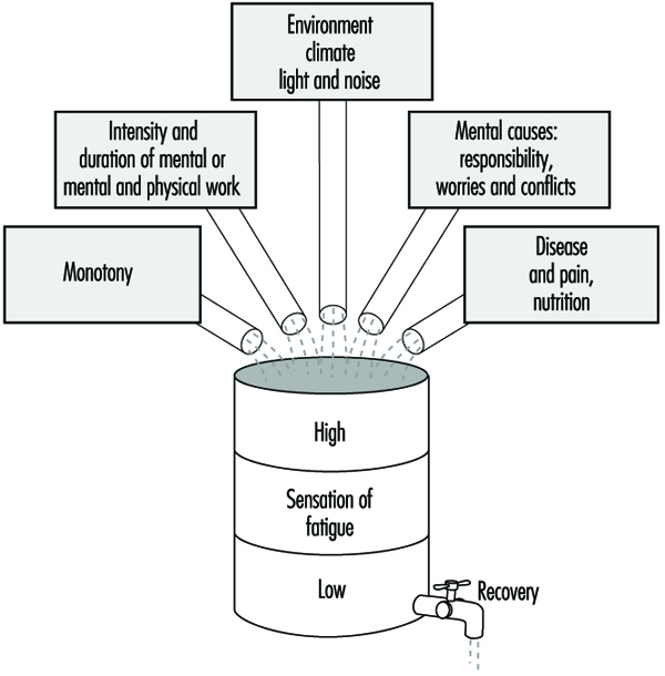
Fatigue is a salutary sensation if one can lie down and rest. However, if one disregards this feeling and forces oneself to continue working, the feeling of fatigue increases until it becomes distressing and finally overwhelming. This daily experience demonstrates clearly the biological significance of fatigue which plays a part in sustaining life, similar to that played by other sensations such as, for example, thirst, hunger, fear, etc.
Rest is represented in figure 1 as the emptying of a barrel. The phenomenon of rest can take place normally if the organism remains undisturbed or if at least one essential part of the body is not subjected to stress. This explains the decisive part played on working days by all work breaks, from the short pause during work to the nightly sleep. The simile of the barrel illustrates how necessary it is for normal living to reach a certain equilibrium between the total load borne by the organism and the sum of the possibilities for rest.
Neurophysiological interpretation of fatigue
The progress of neurophysiology during the last few decades has greatly contributed to a better understanding of the phenomena triggered off by fatigue in the central nervous system.
The physiologist Hess was the first to observe that electrical stimulation of certain of the diencephalic structures, and more especially of certain of the structures of the medial nucleus of the thalamus, gradually produced an inhibiting effect which showed itself in a deterioration in the capacity for reaction and in a tendency to sleep. If the stimulation was continued for a certain time, general relaxation was followed by sleepiness and finally by sleep. It was later proved that starting from these structures, an active inhibition may extend to the cerebral cortex where all conscious phenomena are centered. This is reflected not only in behaviour, but also in the electrical activity of the cerebral cortex. Other experiments have also succeeded in initiating inhibitions from other subcortical regions.
The conclusion which can be drawn from all these studies is that there are structures located in the diencephalon and mesencephalon which represent an effective inhibiting system and which trigger off fatigue with all its accompanying phenomena.
Inhibition and activation
Numerous experiments performed on animals and humans have shown that the general disposition of them both to reaction depends not only on this system of inhibition but essentially also on a system functioning in an antagonistic manner, known as the reticular ascending system of activation. We know from experiments that the reticular formation contains structures that control the degree of wakefulness, and consequently the general dispositions to a reaction. Nervous links exist between these structures and the cerebral cortex where the activating influences are exerted on the consciousness. Moreover, the activating system receives stimulation from the sensory organs. Other nervous connections transmit impulses from the cerebral cortex—the area of perception and thought—to the activation system. On the basis of these neurophysiological concepts, it can be established that external stimuli, as well as influences originating in the areas of consciousness, may, in passing through the activating system, stimulate a disposition to a reaction.
In addition, many other investigations make it possible to conclude that stimulation of the activating system frequently spreads also from the vegetative centers, and cause the organism to orient towards the expenditure of energy, towards work, struggle, flight, etc. (ergotropic conversion of the internal organs). Conversely, it appears that stimulation of the inhibiting system within the sphere of the vegetative nervous system causes the organism to tend towards rest, reconstitution of its reserves of energy, phenomena of assimilation (trophotropic conversion).
By synthesis of all these neurophysiological findings, the following conception of fatigue can be established: the state and feeling of fatigue are conditioned by the functional reaction of the consciousness in the cerebral cortex, which is, in turn, governed by two mutually antagonistic systems—the inhibiting system and the activating system. Thus, the disposition of humans to work depends at each moment on the degree of activation of the two systems: if the inhibiting system is dominant, the organism will be in a state of fatigue; when the activating system is dominant, it will exhibit an increased disposition to work.
This psychophysiological conception of fatigue makes it possible to understand certain of its symptoms which are sometimes difficult to explain. Thus, for example, a feeling of fatigue may disappear suddenly when some unexpected outside event occurs or when emotional tension develops. It is clear in both these cases that the activating system has been stimulated. Conversely, if the surroundings are monotonous or work seems boring, the functioning of the activating system is diminished and the inhibiting system becomes dominant. This explains why fatigue appears in a monotonous situation without the organism being subjected to any workload.
Figure 2 depicts diagrammatically the notion of the mutually antagonistic systems of inhibition and activation.
Figure 2. Diagrammatic presentation of the control of disposition to work by means of inhibiting and activating systems

Clinical fatigue
It is a matter of common experience that pronounced fatigue occurring day after day will gradually produce a state of chronic fatigue. The feeling of fatigue is then intensified and comes on not only in the evening after work but already during the day, sometimes even before the start of work. A feeling of malaise, frequently of an emotive nature, accompanies this state. The following symptoms are often observed in persons suffering from fatigue: heightened psychic emotivity (antisocial behaviour, incompatibility), tendency to depression (unmotivated anxiety), and lack of energy with loss of initiative. These psychic effects are often accompanied by an unspecific malaise and manifest themselves by psychosomatic symptoms: headaches, vertigo, cardiac and respiratory functional disturbances, loss of appetite, digestive disorders, insomnia, etc.
In view of the tendency towards morbid symptoms that accompany chronic fatigue, it may justly be called clinical fatigue. There is a tendency towards increased absenteeism, and particularly to more absences for short periods. This would appear to be caused both by the need for rest and by increased morbidity. The state of chronic fatigue occurs particularly among persons exposed to psychic conflicts or difficulties. It is sometimes very difficult to distinguish the external and internal causes. In fact, it is almost impossible to distinguish cause and effect in clinical fatigue: a negative attitude towards work, superiors or workplace may just as well be the cause of clinical fatigue as the result.
Research has shown that the switchboard operators and supervisory personnel employed in telecommunications services exhibited a significant increase in physiological symptoms of fatigue after their work (visual reaction time, flicker fusion frequency, dexterity tests). Medical investigations revealed that in these two groups of workers there was a significant increase in neurotic conditions, irritability, difficulty in sleeping and in the chronic feeling of lassitude, by comparison with a similar group of women employed in the technical branches of the postal, telephone and telegraphic services. The accumulation of symptoms was not always due to a negative attitude on the part of the women affected their job or their working conditions.
Preventive Measures
There is no panacea for fatigue but much can be done to alleviate the problem by attention to general working conditions and the physical environment at the workplace. For example much can be achieved by the correct arrangement of hours of work, provision of adequate rest periods and suitable canteens and restrooms; adequate paid holidays should also be given to workers. The ergonomic study of the workplace can also help in the reduction of fatigue by ensuring that seats, tables, and workbenches are of suitable dimensions and that the workflow is correctly organized. In addition, noise control, air-conditioning, heating, ventilation, and lighting may all have a beneficial effect on delaying the onset of fatigue in workers.
Monotony and tension may also be alleviated by controlled use of colour and decoration in the surroundings, intervals of music and sometimes breaks for physical exercises for sedentary workers. Training of workers and in particular of supervisory and management staff also play an important part.
Biomechanics
Aims and Principles
Biomechanics is a discipline that approaches the study of the body as though it were solely a mechanical system: all parts of the body are likened to mechanical structures and are studied as such. The following analogies may, for example, be drawn:
- bones: levers, structural members
- flesh: volumes and masses
- joints: bearing surfaces and articulations
- joint linings: lubricants
- muscles: motors, springs
- nerves: feedback control mechanisms
- organs: power supplies
- tendons: ropes
- tissue: springs
- body cavities: balloons.
The main aim of biomechanics is to study the way the body produces force and generates movement. The discipline relies primarily on anatomy, mathematics and physics; related disciplines are anthropometry (the study of human body measurements), work physiology and kinesiology (the study of the principles of mechanics and anatomy in relation to human movement).
In considering the occupational health of the worker, biomechanics helps to understand why some tasks cause injury and ill health. Some relevant types of adverse health effect are muscle strain, joint problems, back problems and fatigue.
Back strains and sprains and more serious problems involving the intervertebral discs are common examples of workplace injuries that can be avoided. These often occur because of a sudden particular overload, but may also reflect the exertion of excessive forces by the body over many years: problems may occur suddenly or may take time to develop. An example of a problem that develops over time is “seamstress’s finger”. A recent description describes the hands of a woman who, after 28 years of work in a clothing factory, as well as sewing in her spare time, developed hardened thickened skin and an inability to flex her fingers (Poole 1993). (Specifically, she suffered from a flexion deformity of the right index finger, prominent Heberden’s nodes on the index finger and thumb of the right hand, and a prominent callosity on the right middle finger due to constant friction from the scissors.) X-ray films of her hands showed severe degenerative changes in the outermost joints of her right index and middle fingers, with loss of joint space, articular sclerosis (hardening of tissue), osteophytes (bony growths at the joint) and bone cysts.
Inspection at the workplace showed that these problems were due to repeated hyperextension (bending up) of the outermost finger joint. Mechanical overload and restriction in blood flow (visible as a whitening of the finger) would be maximal across these joints. These problems developed in response to repeated muscle exertion in a site other than the muscle.
Biomechanics helps to suggest ways of designing tasks to avoid these types of injuries or of improving poorly designed tasks. Remedies for these particular problems are to redesign the scissors and to alter the sewing tasks to remove the need for the actions performed.
Two important principles of biomechanics are:
- Muscles come in pairs. Muscles can only contract, so for any joint there must be one muscle (or muscle group) to move it one way and a corresponding muscle (or muscle group) to move it in the opposite direction. Figure 1 illustrates the point for the elbow joint.
- Muscles contract most efficiently when the muscle pair is in relaxed balance. The muscle acts most efficiently when it is in the midrange of the joint it flexes. This is so for two reasons: first, if the muscle tries to contract when it is shortened, it will pull against the elongated opposing muscle. Because the latter is stretched, it will apply an elastic counterforce that the contracting muscle must overcome. Figure 2 shows the way in which muscle force varies with muscle length.
Figure 1. Skeletal muscles occur in pairs in order to initiate or reverse a movement
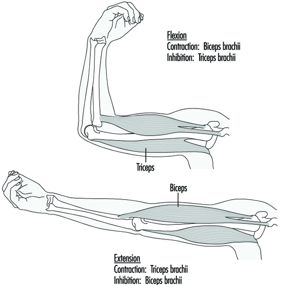
Figure 2. Muscle tension varies with muscle length

Second, if the muscle tries to contract at other than the midrange of the movement of the joint, it will operate at a mechanical disadvantage. Figure 3 illustrates the change in mechanical advantage for the elbow in three different positions.
Figure 3. Optimal positions for joint movement

An important criterion for work design follows from these principles: Work should be arranged so that it occurs with the opposing muscles of each joint in relaxed balance. For most joints, this means that the joint should be at about its midrange of movement.
This rule also means that muscle tension will be at a minimum while a task is performed. One example of the infringement of the rule is the overuse syndrome (RSI, or repetitive strain injury) which affects the muscles of the top of the forearm in keyboard operators who habitually operate with the wrist flexed up. Often this habit is forced on the operator by the design of the keyboard and workstation.
Applications
The following are some examples illustrating the application of biomechanics.
The optimum diameter of tool handles
The diameter of a handle affects the force that the muscles of the hand can apply to a tool. Research has shown that the optimum handle diameter depends on the use to which the tool is put. For exerting thrust along the line of the handle, the best diameter is one that allows the fingers and thumb to assume a slightly overlapping grip. This is about 40 mm. To exert torque, a diameter of about 50-65 mm is optimal. (Unfortunately, for both purposes most handles are smaller than these values.)
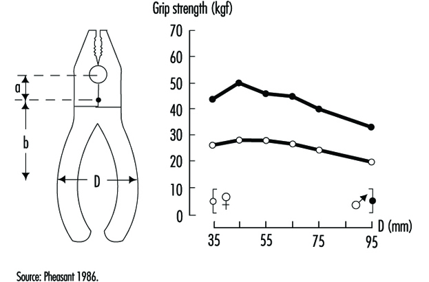
The use of pliers
As a special case of a handle, the ability to exert force with pliers depends on the handle separation, as shown in figure 4.
Figure 4. Grip strength of pliers jaws exerted by male and female users as a function of handle separation
Seated posture
Electromyography is a technique that can be used to measure muscle tension. In a study of the tension in the erector spinae muscles (of the back) of seated subjects, it was found that leaning back (with the backrest inclined) reduced the tension in these muscles. The effect can be explained because the backrest takes more of the weight of the upper body.
X-ray studies of subjects in a variety of postures showed that the position of relaxed balance of the muscles that open and close the hip joint corresponds to a hip angle of about 135º. This is close to the position (128º) naturally adopted by this joint in weightless conditions (in space). In the seated posture, with an angle of 90º at the hip, the hamstring muscles that run over both the knee and hip joints tend to pull the sacrum (the part of the vertebral column that connects with the pelvis) into a vertical position. The effect is to remove the natural lordosis (curvature) of the lumbar spine; chairs should have appropriate backrests to correct for this effort.
Screwdriving
Why are screws inserted clockwise? The practice probably arose in unconscious recognition that the muscles that rotate the right arm clockwise (most people are right-handed) are larger (and therefore more powerful) that the muscles that rotate it anticlockwise.
Note that left-handed people will be at a disadvantage when inserting screws by hand. About 9% of the population are left-handed and will therefore require special tools in some situations: scissors and can openers are two such examples.
A study of people using screwdrivers in an assembly task revealed a more subtle relation between a particular movement and a particular health problem. It was found that the greater the elbow angle (the straighter the arm), the more people had inflammation at the elbow. The reason for this effect is that the muscle that rotates the forearm (the biceps) also pulls the head of the radius (lower arm bone) onto the capitulum (rounded head) of the humerus (upper arm bone). The increased force at the higher elbow angle caused greater frictional force at the elbow, with consequent heating of the joint, leading to the inflammation. At the higher angle, the muscle also had to pull with greater force to effect the screwing action, so a greater force was applied than would have been required with the elbow at about 90º. The solution was to move the task closer to the operators to reduce the elbow angle to about 90º.
The cases above demonstrate that a proper understanding of anatomy is required for the application of biomechanics in the workplace. Designers of tasks may need to consult experts in functional anatomy to anticipate the types of problems discussed. (The Pocket Ergonomist (Brown and Mitchell 1986) based on electromyographical research, suggests many ways of reducing physical discomfort at work.)
Manual Material Handling
The term manual handling includes lifting, lowering, pushing, pulling, carrying, moving, holding and restraining, and encompasses a large part of the activities of working life.
Biomechanics has obvious direct relevance to manual handling work, since muscles must move to carry out tasks. The question is: how much physical work can people be reasonably expected to do? The answer depends on the circumstances; there are really three questions that need to be asked. Each one has an answer that is based on scientifically researched criteria:
- How much can be handled without damage to the body (in the form, for example, of muscle strain, disc injury or joint problems)? This is called the biomechanical criterion.
- How much can be handled without overexerting the lungs (breathing hard to the point of panting)? This is called the physiological criterion.
- How much do people feel able to handle comfortably? This is called the psychophysical criterion.
There is a need for these three different criteria because there are three broadly different reactions that can occur to lifting tasks: if the work goes on all day, the concern will be how the person feels about the task—the psychophysical criterion; if the force to be applied is large, the concern would be that muscles and joints are not overloaded to the point of damage—the biomechanical criterion; and if the rate of work is too great, then it may well exceed the physiological criterion, or the aerobic capacity of the person.
Many factors determine the extent of the load placed on the body by a manual handling task. All of them suggest opportunities for control.
Posture and Movements
If the task requires a person to twist or reach forward with a load, the risk of injury is greater. The workstation can often be redesigned to prevent these actions. More back injuries occur when the lift begins at ground level compared to mid-thigh level, and this suggests simple control measures. (This applies to high lifting as well.)
The load.
The load itself may influence handling because of its weight and its location. Other factors, such as its shape, its stability, its size and its slipperiness may all affect the ease of a handling task.
Organization and environment.
The way work is organized, both physically and over time (temporally), also influences handling. It is better to spread the burden of unloading a truck in a delivery bay over several people for an hour rather than to ask one worker to spend all day on the task. The environment influences handling—poor light, cluttered or uneven floors and poor housekeeping may all cause a person to stumble.
Personal factors.
Personal handling skills, the age of the person and the clothing worn also can influence handling requirements. Education for training and lifting are required both to provide necessary information and to allow time for the development of the physical skills of handling. Younger people are more at risk; on the other hand, older people have less strength and less physiological capacity. Tight clothing can increase the muscle force required in a task as people strain against the tight cloth; classic examples are the nurse’s smock uniform and tight overalls when people do work above their heads.
Recommended Weight Limits
The points mentioned above indicate that it is impossible to state a weight that will be “safe” in all circumstances. (Weight limits have tended to vary from country to country in an arbitrary manner. Indian dockers, for example, were once “allowed” to lift 110 kg, while their counterparts in the former People’s Democratic Republic of Germany were “limited” to 32 kg.) Weight limits have also tended to be too great. The 55 kg suggested in many countries is now thought to be far too great on the basis of recent scientific evidence. The National Institute for Occupational Safety and Health (NIOSH) in the United States has adopted 23 kg as a load limit in 1991 (Waters et al. 1993).
Each lifting task needs to be assessed on its own merits. A useful approach to determining a weight limit for a lifting task is the equation developed by NIOSH:
RWL = LC x HM x VM x DM x AM x CM x FM
Where
RWL = recommended weight limit for the task in question
HM = the horizontal distance from the centre of gravity of the load to the midpoint between the ankles (minimum 15 cm, maximum 80 cm)
VM = the vertical distance between the centre of gravity of the load and the floor at the start of the lift (maximum 175 cm)
DM = the vertical travel of the lift (minimum 25 cm, maximum 200 cm)
AM = asymmetry factor–the angle the task deviates from straight out in front of the body
CM = coupling multiplier–the ability to get a good grip on the item to be lifted, which is found in a reference table
FM = frequency multipliers–the frequency of the lifting.
All variables of length in the equation are expressed in units of centimetres. It should be noted that 23 kg is the maximum weight that NIOSH recommends for lifting. This has been reduced from 40 kg after observation of many people doing many lifting tasks has revealed that the average distance from the body of the start of the lift is 25 cm, not the 15 cm assumed in an earlier version of the equation (NIOSH 1981).
Lifting index.
By comparing the weight to be lifted in the task and the RWL, a lifting index (LI) can be obtained according to the relationship:
LI=(weight to be handled)/RWL.
Therefore, particularly valuable use of the NIOSH equation is the placing of lifting tasks in order of severity, using the lifting index to set priorities for action. (The equation has a number of limitations, however, that need to be understood for its most effective application. See Waters et al. 1993).
Estimating Spinal Compression Imposed by the Task
Computer software is available to estimate the spinal compression produced by a manual handling task. The 2D and 3D Static Strength Prediction Programs from the University of Michigan (“Backsoft”) estimate spinal compression. The inputs required to the program are:
- the posture in which the handling activity is performed
- the force exerted
- the direction of the force exertion
- the number of hands exerting the force
- the percentile of the population under study.
The 2D and 3D programs differ in that the 3D software allows computations applying to postures in three dimensions. The program output gives spinal compression data and lists the percentage of the population selected that would be able to do the particular task without exceeding suggested limits for six joints: ankle, knee, hip, first lumbar disc-sacrum, shoulder, and elbow. This method also has a number of limitations that need to be fully understood in order to derive maximum value out of the program.
Postures at Work
A person’s posture at work—the mutual organization of the trunk, head and extremities—can be analysed and understood from several points of view. Postures aim at advancing the work; thus, they have a finality which influences their nature, their time relation and their cost (physiological or otherwise) to the person in question. There is a close interaction between the body’s physiological capacities and characteristics and the requirement of the work.
Musculoskeletal load is a necessary element in body functions and indispensable in well-being. From the standpoint of the design of the work, the question is to find the optimal balance between the necessary and the excessive.
Postures have interested researchers and practitioners for at least the following reasons:
- A posture is the source of musculoskeletal load. Except for relaxed standing, sitting and lying horizontally, muscles have to create forces to balance the posture and/or control movements. In classical heavy tasks, for example in the construction industry or in the manual handling of heavy materials, external forces, both dynamic and static, add to the internal forces in the body, sometimes creating high loads which may exceed the capacity of the tissues. (See figure 1) Even in relaxed postures, when muscle work approaches zero, tendons and joints may be loaded and show signs of fatigue. A job with low apparent loading—an example being that of a microscopist—may become tedious and strenuous when it is carried out over a long period of time.
- Posture is closely related to balance and stability. In fact, posture is controlled by several neural reflexes where input from tactile sensations and visual cues from the surroundings play an important role. Some postures, like reaching objects from a distance, are inherently unstable. Loss of balance is a common immediate cause of work accidents. Some work tasks are performed in an environment where stability cannot always be guaranteed, for example, in the construction industry.
- Posture is the basis of skilled movements and visual observation. Many tasks require fine, skilled hand movements and close observation of the object of the work. In such cases, posture becomes the platform of these actions. Attention is directed to the task, and the postural elements are enlisted to support the tasks: the posture becomes motionless, the mus-cular load increases and becomes more static. A French research group showed in their classical study that immobility and musculoskeletal load increased when the rate of work increased (Teiger, Laville and Duraffourg 1974).
- Posture is a source of information on the events taking place at work. Observing posture may be intentional or unconscious. Skilful supervisors and workers are known to use postural observations as indicators of the work process. Often, observing postural information is not conscious. For example, on an oil drilling derrick, postural cues have been used to communicate messages between team members during different phases of a task. This takes place under conditions where other means of communication are not possible.
Figure 1. Too high hand positions or forward bending are amont the most commom ways of creating “static” load

Safety, Health and Working Postures
From a safety and health point of view, all the aspects of posture described above may be important. However, postures as a source of musculoskeletal illnesses such as low back diseases have attracted the most attention. Musculoskeletal problems related to repetitive work are also connected to postures.
Low back pain (LBP) is a generic term for various low back diseases. It has many causes and posture is one possible causal element. Epidemiological studies have shown that physically heavy work is conducive to LBP and that postures are one element in this process. There are several possible mechanisms which explain why certain postures may cause LBP. Forward bending postures increase the load on the spine and ligaments, which are especially vulnerable to loads in a twisted posture. External loads, especially dynamic ones, such as those imposed by jerks and slipping, may increase the loads on the back by a large factor.
From a safety and health standpoint, it is important to identify bad postures and other postural elements as part of the safety and health analysis of work in general.
Recording and Measuring Working Postures
Postures can be recorded and measured objectively by the use of visual observation or more or less sophisticated measuring techniques. They can also be recorded by using self-rating schemes. Most methods consider posture as one of the elements in a larger context, for example, as part of the job content—as do the AET and Renault’s Les profils des postes (Landau and Rohmert 1981; RNUR 1976)—or as a starting point for biomechanical calculations that also take into account other components.
In spite of the advancements in measuring technology, visual observation remains, under field conditions, the only practicable means of systematically recording postures. However, the precision of such measurements remains low. In spite of this, postural observations can be a rich source of information on work in general.
The following short list of measuring methods and techniques presents selected examples:
- Self-reporting questionnaires and diaries. Self-reporting questionnaires and diaries are an economical means of collecting postural information. Self-reporting is based on the perception of the subject and usually deviates greatly from “objectively” observed postures, but may still convey important information about the tediousness of the work.
- Observation of postures. The observation of postures includes the purely visual recording of the postures and their components as well as methods in which an interview completes the information. Computer support is usually available for these methods. Many methods are available for visual observations. The method may simply contain a catalogue of actions, including postures of the trunk and limbs (e.g., Keyserling 1986; Van der Beek, Van Gaalen and Frings-Dresen 1992) .The OWAS method proposes a structured scheme for the analysis, rating and evaluation of trunk and limb postures designed for field conditions (Karhu, Kansi and Kuorinka 1977). The recording and analysis method may contain notation schemes, some of them quite detailed (as with the posture targeting method, by Corlett and Bishop 1976), and they may provide a notation for the position of many anatomical elements for each element of the task (Drury 1987).
- Computer-aided postural analyses. Computers have aided postural analyses in many ways. Portable computers and special programs allow easy recording and fast analysis of postures. Persson and Kilbom (1983) have developed the program VIRA for upper-limb study; Kerguelen (1986) has produced a complete recording and analysis package for work tasks; Kivi and Mattila (1991) have designed a computerized OWAS version for recording and analysis.
Video is usually an integral part of the recording and analysis process. The US National Institute for Occupational Safety and Health (NIOSH) has presented guidelines for using video methods in hazard analysis (NIOSH 1990).
Biomechanical and anthropometrical computer programs offer specialized tools for analysing some postural elements in the work activity and in the laboratory (e.g., Chaffin 1969).
Factors Affecting Working Postures
Working postures serve a goal, a finality outside themselves. That is why they are related to external working conditions. Postural analysis that does not take into account the work environment and the task itself is of limited interest to ergonomists.
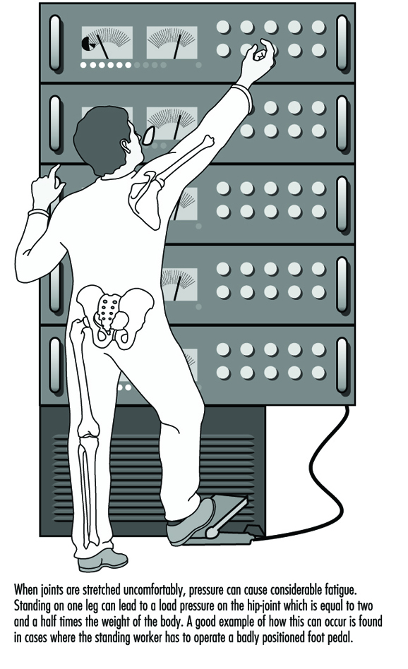
The dimensional characteristics of the workplace largely define the postures (as in the case of a sitting task), even for dynamic tasks (for example, the handling of material in a confined space). The loads to be handled force the body into a certain posture, as does the weight and nature of the working tool. Some tasks require that body weight be used to support a tool or to apply force on the object of the work, as shown, for example in figure 2.
Figure 2. Ergonomic aspects of standing
Individual differences, age and sex influence postures. In fact, it has been found that a “typical” or “best” posture, for example in manual handling, is largely fiction. For each individual and each working situation, there are a number of alternative “best” postures from the standpoint of different criteria.
Job Aids and Supports for Working Postures
Belts, lumbar supports and orthotics have been recommended for tasks with a risk of low back pain or upper-limb musculoskeletal injuries. It has been assumed that these devices give support to muscles, for example, by controlling intra-abdominal pressure or hand movements. They are also expected to limit the range of movement of the elbow, wrist or fingers. There is no evidence that modifying postural elements with these devices would help to avoid musculoskeletal problems.
Postural supports in the workplace and on machinery, such as handles, supporting pads for kneeling, and seating aids, may be useful in alleviating postural loads and pain.
Safety and Health Regulations concerning Postural Elements
Postures or postural elements have not been subject to regulatory activities per se. However, several documents either contain statements which have a bearing on postures or include the issue of postures as an integral element of a regulation. A complete picture of the existing regulatory material is not available. The following references are presented as examples.
- The International Labour Organization published a Recommendation in 1967 on maximum loads to be handled. Although the Recommendation does not regulate postural elements as such, it has a significant bearing on postural strain. The Recommendation is now outdated but has served an important purpose in focusing attention on problems in manual material handling.
- The NIOSH lifting guidelines (NIOSH 1981), as such, are not regulations either, but they have attained that status. The guidelines derive weight limits for loads using the location of the load—a postural element—as a basis.
- In the International Organization for Standardization as well as in the European Community, ergonomics standards and directives exist which contain matter relating to postural elements (CEN 1990 and 1991).
Muscular Work
Muscular Work in Occupational Activities
In industrialized countries around 20% of workers are still employed in jobs requiring muscular effort (Rutenfranz et al. 1990). The number of conventional heavy physical jobs has decreased, but, on the other hand, many jobs have become more static, asymmetrical and stationary. In developing countries, muscular work of all forms is still very common.
Muscular work in occupational activities can be roughly divided into four groups: heavy dynamic muscle work, manual materials handling, static work and repetitive work. Heavy dynamic work tasks are found in forestry, agriculture and the construction industry, for example. Materials handling is common, for example, in nursing, transportation and warehousing, while static loads exist in office work, the electronics industry and in repair and maintenance tasks. Repetitive work tasks can be found in the food and wood-processing industries, for example.
It is important to note that manual materials handling and repetitive work are basically either dynamic or static muscular work, or a combination of these two.
Physiology of Muscular Work
Dynamic muscular work
In dynamic work, active skeletal muscles contract and relax rhythmically. The blood flow to the muscles is increased to match metabolic needs. The increased blood flow is achieved through increased pumping of the heart (cardiac output), decreased blood flow to inactive areas, such as kidneys and liver, and increased number of open blood vessels in the working musculature. Heart rate, blood pressure, and oxygen extraction in the muscles increase linearly in relation to working intensity. Also, pulmonary ventilation is heightened owing to deeper breathing and increased breathing frequency. The purpose of activating the whole cardio-respiratory system is to enhance oxygen delivery to the active muscles. The level of oxygen consumption measured during heavy dynamic muscle work indicates the intensity of the work. The maximum oxygen consumption (VO2max) indicates the person’s maximum capacity for aerobic work. Oxygen consumption values can be translated to energy expenditure (1 litre of oxygen consumption per minute corresponds to approximately 5 kcal/min or 21 kJ/min).
In the case of dynamic work, when the active muscle mass is smaller (as in the arms), maximum working capacity and peak oxygen consumption are smaller than in dynamic work with large muscles. At the same external work output, dynamic work with small muscles elicits higher cardio-respiratory responses (e.g., heart rate, blood pressure) than work with large muscles (figure 1).
Figure 1. Static versus dynamic work
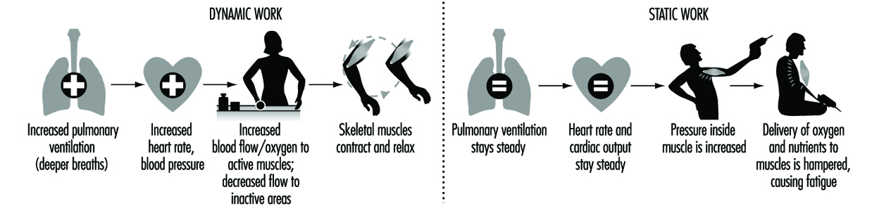
Static muscle work
In static work, muscle contraction does not produce visible movement, as, for example, in a limb. Static work increases the pressure inside the muscle, which together with the mechanical compression occludes blood circulation partially or totally. The delivery of nutrients and oxygen to the muscle and the removal of metabolic end-products from the muscle are hampered. Thus, in static work, muscles become fatigued more easily than in dynamic work.
The most prominent circulatory feature of static work is a rise in blood pressure. Heart rate and cardiac output do not change much. Above a certain intensity of effort, blood pressure increases in direct relation to the intensity and the duration of the effort. Furthermore, at the same relative intensity of effort, static work with large muscle groups produces a greater blood pressure response than does work with smaller muscles. (See figure 2)
Figure 2. The expanded stress-strain model modified from Rohmert (1984)

In principle, the regulation of ventilation and circulation in static work is similar to that in dynamic work, but the metabolic signals from the muscles are stronger, and induce a different response pattern.
Consequences of Muscular Overload in Occupational Activities
The degree of physical strain a worker experiences in muscular work depends on the size of the working muscle mass, the type of muscular contractions (static, dynamic), the intensity of contractions, and individual characteristics.
When muscular workload does not exceed the worker’s physical capacities, the body will adapt to the load and recovery is quick when the work is stopped. If the muscular load is too high, fatigue will ensue, working capacity is reduced, and recovery slows down. Peak loads or prolonged overload may result in organ damage (in the form of occupational or work-related diseases). On the other hand, muscular work of certain intensity, frequency, and duration may also result in training effects, as, on the other hand, excessively low muscular demands may cause detraining effects. These relationships are represented by the so-called expanded stress-strain concept developed by Rohmert (1984) (figure 3).
Figure 3. Analysis of acceptable workloads
In general, there is little epidemiological evidence that muscular overload is a risk factor for diseases. However, poor health, disability and subjective overload at work converge in physically demanding jobs, especially with older workers. Furthermore, many risk factors for work-related musculoskeletal diseases are connected to different aspects of muscular workload, such as the exertion of strength, poor working postures, lifting and sudden peak loads.
One of the aims of ergonomics has been to determine acceptable limits for muscular workloads which could be applied for the prevention of fatigue and disorders. Whereas the prevention of chronic effects is the focus of epidemiology, work physiology deals mostly with short-term effects, that is, fatigue in work tasks or during a work day.
Acceptable Workload in Heavy Dynamic Muscular Work
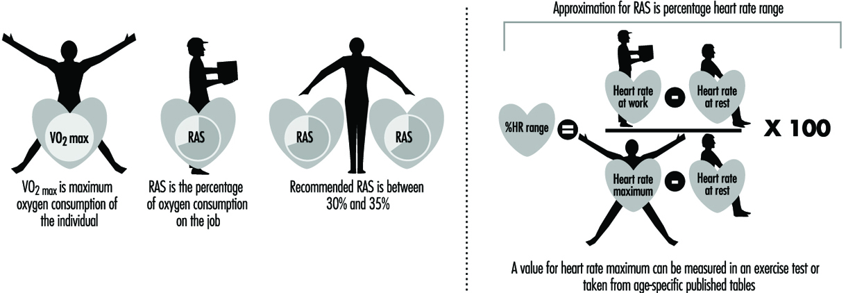
The assessment of acceptable workload in dynamic work tasks has traditionally been based on measurements of oxygen consumption (or, correspondingly, energy expenditure). Oxygen consumption can be measured with relative ease in the field with portable devices (e.g., Douglas bag, Max Planck respirometer, Oxylog, Cosmed), or it can be estimated from heart rate recordings, which can be made reliably at the workplace, for example, with the SportTester device. The use of heart rate in the estimation of oxygen consumption requires that it be individually calibrated against measured oxygen consumption in a standard work mode in the laboratory, i.e., the investigator must know the oxygen consumption of the individual subject at a given heart rate. Heart rate recordings should be treated with caution because they are also affected by such factors as physical fitness, environmental temperature, psychological factors and size of active muscle mass. Thus, heart rate measurements can lead to overestimates of oxygen consumption in the same way that oxygen consumption values can give rise to underestimates of global physiological strain by reflecting only energy requirements.
Relative aerobic strain (RAS) is defined as the fraction (expressed as a percentage) of a worker’s oxygen consumption measured on the job relative to his or her VO2max measured in the laboratory. If only heart rate measurements are available, a close approximation to RAS can be made by calculating a value for percentage heart rate range (% HR range) with the so-called Karvonen formula as in figure 3.
VO2max is usually measured on a bicycle ergometer or treadmill, for which the mechanical efficiency is high (20-25%). When the active muscle mass is smaller or the static component is higher, VO2max and mechanical efficiency will be smaller than in the case of exercise with large muscle groups. For example, it has been found that in the sorting of postal parcels the VO2max of workers was only 65% of the maximum measured on a bicycle ergometer, and the mechanical efficiency of the task was less than 1%. When guidelines are based on oxygen consumption, the test mode in the maximal test should be as close as possible to the real task. This goal, however, is difficult to achieve.
According to Åstrand’s (1960) classical study, RAS should not exceed 50% during an eight-hour working day. In her experiments, at a 50% workload, body weight decreased, heart rate did not reach steady state and subjective discomfort increased during the day. She recommended a 50% RAS limit for both men and women. Later on she found that construction workers spontaneously chose an average RAS level of 40% (range 25-55%) during a working day. Several more recent studies have indicated that the acceptable RAS is lower than 50%. Most authors recommend 30-35% as an acceptable RAS level for the entire working day.
Originally, the acceptable RAS levels were developed for pure dynamic muscle work, which rarely occurs in real working life. It may happen that acceptable RAS levels are not exceeded, for example, in a lifting task, but the local load on the back may greatly exceed acceptable levels. Despite its limitations, RAS determination has been widely used in the assessment of physical strain in different jobs.
In addition to the measurement or estimation of oxygen consumption, other useful physiological field methods are also available for the quantification of physical stress or strain in heavy dynamic work. Observational techniques can be used in the estimation of energy expenditure (e.g., with the aid of the Edholm scale) (Edholm 1966). Rating of perceived exertion (RPE) indicates the subjective accumulation of fatigue. New ambulatory blood pressure monitoring systems allow more detailed analyses of circulatory responses.
Acceptable Workload in Manual Materials Handling
Manual materials handling includes such work tasks as lifting, carrying, pushing and pulling of various external loads. Most of the research in this area has focused on low back problems in lifting tasks, especially from the biomechanical point of view.
A RAS level of 20-35% has been recommended for lifting tasks, when the task is compared to an individual maximum oxygen consumption obtained from a bicycle ergometer test.
Recommendations for a maximum permissible heart rate are either absolute or related to the resting heart rate. The absolute values for men and women are 90-112 beats per minute in continuous manual materials handling. These values are about the same as the recommended values for the increase in heart rate above resting levels, that is, 30 to 35 beats per minute. These recommendations are also valid for heavy dynamic muscle work for young and healthy men and women. However, as mentioned previously, heart rate data should be treated with caution, because it is also affected by other factors than muscle work.
The guidelines for acceptable workload for manual materials handling based on biomechanical analyses comprise several factors, such as weight of the load, handling frequency, lifting height, distance of the load from the body and physical characteristics of the person.
In one large-scale field study (Louhevaara, Hakola and Ollila 1990) it was found that healthy male workers could handle postal parcels weighing 4 to 5 kilograms during a shift without any signs of objective or subjective fatigue. Most of the handling occurred below shoulder level, the average handling frequency was less than 8 parcels per minute and the total number of parcels was less than 1,500 per shift. The mean heart rate of the workers was 101 beats per minute and their mean oxygen consumption 1.0 l/min, which corresponded to 31% RAS as related to bicycle maximum.
Observations of working postures and use of force carried out for example according to OWAS method (Karhu, Kansi and Kuorinka 1977), ratings of perceived exertion and ambulatory blood pressure recordings are also suitable methods for stress and strain assessments in manual materials handling. Electromyography can be used to assess local strain responses, for example in arm and back muscles.
Acceptable Workload for Static Muscular Work
Static muscular work is required chiefly in maintaining working postures. The endurance time of static contraction is exponentially dependent on the relative force of contraction. This means, for example, that when the static contraction requires 20% of the maximum force, the endurance time is 5 to 7 minutes, and when the relative force is 50%, the endurance time is about 1 minute.
Older studies indicated that no fatigue will be developed when the relative force is below 15% of the maximum force. However, more recent studies have indicated that the acceptable relative force is specific to the muscle or muscle group, and is 2 to 5% of the maximum static strength. These force limits are, however, difficult to use in practical work situations because they require electromyographic recordings.
For the practitioner, fewer field methods are available for the quantification of strain in static work. Some observational methods (e.g., the OWAS method) exist to analyse the proportion of poor working postures, that is, postures deviating from normal middle positions of the main joints. Blood pressure measurements and ratings of perceived exertion may be useful, whereas heart rate is not so applicable.
Acceptable Workload in Repetitive Work
Repetitive work with small muscle groups resembles static muscle work from the point of view of circulatory and metabolic responses. Typically, in repetitive work muscles contract over 30 times per minute. When the relative force of contraction exceeds 10% of the maximum force, endurance time and muscle force start to decrease. However, there is wide individual variation in endurance times. For example, the endurance time varies between two to fifty minutes when the muscle contracts 90 to 110 times per minute at a relative force level of 10 to 20% (Laurig 1974).
It is very difficult to set any definitive criteria for repetitive work, because even very light levels of work (as with the use of a microcomputer mouse) may cause increases in intramuscular pressure, which may sometimes lead to swelling of muscle fibres, pain and reduction in muscle strength.
Repetitive and static muscle work will cause fatigue and reduced work capacity at very low relative force levels. Therefore, ergonomic interventions should aim to minimize the number of repetitive movements and static contractions as far as possible. Very few field methods are available for strain assessment in repetitive work.
Prevention of Muscular Overload
Relatively little epidemiological evidence exists to show that muscular load is harmful to health. However, work physiological and ergonomic studies indicate that muscular overload results in fatigue (i.e., decrease in work capacity) and may reduce productivity and quality of work.
The prevention of muscular overload may be directed to the work content, the work environment and the worker. The load can be adjusted by technical means, which focus on the work environment, tools, and/or the working methods. The fastest way to regulate muscular workload is to increase the flexibility of working time on an individual basis. This means designing work-rest regimens which take into account the workload and the needs and capacities of the individual worker.
Static and repetitive muscular work should be kept at a minimum. Occasional heavy dynamic work phases may be useful for the maintenance of endurance type physical fitness. Probably, the most useful form of physical activity that can be incorporated into a working day is brisk walking or stair climbing.
Prevention of muscular overload, however, is very difficult if a worker’s physical fitness or working skills are poor. Appropriate training will improve working skills and may reduce muscular loads at work. Also, regular physical exercise during work or leisure time will increase the muscular and cardio-respiratory capacities of the worker.
Anthropometry
This article is adapted from the 3rd edition of the Encyclopaedia of Occupational Health and Safety.
Anthropometry is a fundamental branch of physical anthropology. It represents the quantitative aspect. A wide system of theories and practice is devoted to defining methods and variables to relate the aims in the different fields of application. In the fields of occupational health, safety and ergonomics anthropometric systems are mainly concerned with body build, composition and constitution, and with the dimensions of the human body’s interrelation to workplace dimensions, machines, the industrial environment, and clothing.
Anthropometric variables
An anthropometric variable is a measurable characteristic of the body that can be defined, standardized and referred to a unit of measurement. Linear variables are generally defined by landmarks that can be precisely traced to the body. Landmarks are generally of two types: skeletal-anatomical, which may be found and traced by feeling bony prominences through the skin, and virtual landmarks that are simply found as maximum or minimum distances using the branches of a caliper.
Anthropometric variables have both genetic and environmental components and may be used to define individual and population variability. The choice of variables must be related to the specific research purpose and standardized with other research in the same field, as the number of variables described in the literature is extremely large, up to 2,200 having been described for the human body.
Anthropometric variables are mainly linear measures, such as heights, distances from landmarks with subject standing or seated in standardized posture; diameters, such as distances between bilateral landmarks; lengths, such as distances between two different landmarks; curved measures, namely arcs, such as distances on the body surface between two landmarks; and girths, such as closed all-around measures on body surfaces, generally positioned at at least one landmark or at a defined height.
Other variables may require special methods and instruments. For instance skinfold thickness is measured by means of special constant pressure calipers. Volumes are measured by calculation or by immersion in water. To obtain full information on body surface characteristics, a computer matrix of surface points may be plotted using biostereometric techniques.
Instruments
Although sophisticated anthropometric instruments have been described and used with a view to automated data collection, basic anthropometric instruments are quite simple and easy to use. Much care must be taken to avoid common errors resulting from misinterpretation of landmarks and incorrect postures of subjects.
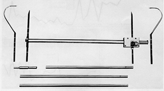
The standard anthropometric instrument is the anthropometer—a rigid rod 2 metres long, with two counter-reading scales, with which vertical body dimensions, such as heights of landmarks from floor or seat, and transverse dimensions, such as diameters, can be taken.
Commonly the rod can be split into 3 or 4 sections which fit into one another. A sliding branch with a straight or curved claw makes it possible to measure distances from the floor for heights, or from a fixed branch for diameters. More elaborate anthropometers have a single scale for heights and diameters to avoid scale errors, or are fitted with digital mechanical or electronic reading devices (figure 1).
A stadiometer is a fixed anthropometer, generally used only for stature and frequently associated with a weight beam scale.
For transverse diameters a series of calipers may be used: the pelvimeter for measures up to 600 mm and the cephalometer up to 300 mm. The latter is particularly suitable for head measurements when used together with a sliding compass (figure 2).
Figure 2. A cephalometer together with a sliding compass

The foot-board is used for measuring the feet and the head-board provides cartesian co-ordinates of the head when oriented in the “Frankfort plane” (a horizontal plane passing through porion and orbitale landmarks of the head).The hand may be measured with a caliper, or with a special device composed of five sliding rulers.
Skinfold thickness is measured with a constant-pressure skinfold caliper generally with a pressure of 9.81 x 10⁴ Pa (the pressure imposed by a weight of 10 g on an area of 1 mm2).
For arcs and girths a narrow, flexible steel tape with flat section is used. Self-straightening steel tapes must be avoided.
Systems of variables
A system of anthropometric variables is a coherent set of body measurements to solve some specific problems.
In the field of ergonomics and safety, the main problem is fitting equipment and workspace to humans and tailoring clothes to the right size.
Equipment and workspace require mainly linear measures of limbs and body segments that can easily be calculated from landmark heights and diameters, whereas tailoring sizes are based mainly on arcs, girths and flexible tape lengths. Both systems may be combined according to need.
In any case, it is absolutely necessary to have a precise space reference for each measurement. The landmarks must, therefore, be linked by heights and diameters and every arc or girth must have a defined landmark reference. Heights and slopes must be indicated.
In a particular survey, the number of variables has to be limited to the minimum so as to avoid undue stress on the subject and operator.
A basic set of variables for workspace has been reduced to 33 measured variables (figure 3) plus 20 derived by a simple calculation. For a general-purpose military survey, Hertzberg and co-workers use 146 variables. For clothes and general biological purposes the Italian Fashion Board (Ente Italiano della Moda) uses a set of 32 general purpose variables and 28 technical ones. The German norm (DIN 61 516) of control body dimensions for clothes includes 12 variables. The recommendation of the International Organization for Standardization (ISO) for anthropometry includes a core list of 36 variables (see table 1). The International Data on Anthropometry tables published by the ILO list 19 body dimensions for the populations of 20 different regions of the world (Jürgens, Aune and Pieper 1990).
Figure 3. Basic set of anthropometric variables
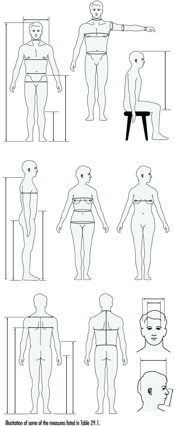
Table 1. Basic anthropometric core list
1.1 Forward reach (to hand grip with subject standing upright against a wall)
1.2 Stature (vertical distance from floor to head vertex)
1.3 Eye height (from floor to inner eye corner)
1.4 Shoulder height (from floor to acromion)
1.5 Elbow height (from floor to radial depression of elbow)
1.6 Crotch height (from floor to pubic bone)
1.7 Finger tip height (from floor to grip axis of fist)
1.8 Shoulder breadth (biacromial diameter)
1.9 Hip breadth, standing (the maximum distance across hips)
2.1 Sitting height (from seat to head vertex)
2.2 Eye height, sitting (from seat to inner corner of the eye)
2.3 Shoulder height, sitting (from seat to acromion)
2.4 Elbow height, sitting (from seat to lowest point of bent elbow)
2.5 Knee height (from foot-rest to the upper surface of thigh)
2.6 Lower leg length (height of sitting surface)
2.7 Forearm-hand length (from back of bent elbow to grip axis)
2.8 Body depth, sitting (seat depth)
2.9 Buttock-knee length (from knee-cap to rearmost point of buttock)
2.10 Elbow to elbow breadth (distance between lateral surface of the elbows)
2.11 Hip breadth, sitting (seat breadth)
3.1 Index finger breadth, proximal (at the joint between medial and proximal phalanges)
3.2 Index finger breadth, distal (at the joint between distal and medial phalanges)
3.3 Index finger length
3.4 Hand length (from tip of middle finger to styloid)
3.5 Handbreadth (at metacarpals)
3.6 Wrist circumference
4.1 Foot breadth
4.2 Foot length
5.1 Heat circumference (at glabella)
5.2 Sagittal arc (from glabella to inion)
5.3 Head length (from glabella to opisthocranion)
5.4 Head breadth (maximum above the ear)
5.5 Bitragion arc (over the head between the ears)
6.1 Waist circumference (at the umbilicus)
6.2 Tibial height (from the floor to the highest point on the antero-medial margin of the glenoid of the tibia)
6.3 Cervical height sitting (to the tip of the spinous process of the 7th cervical vertebra).
Source: Adapted from ISO/DP 7250 1980).
Precision and errors
The precision of living body dimensions must be considered in a stochastic manner because the human body is highly unpredictable, both as a static and as a dynamic structure.
A single individual may grow or change in muscularity and fatness; undergo skeletal changes as a consequence of aging, disease or accidents; or modify behavior or posture. Different subjects differ by proportions, not only by general dimensions. Tall stature subjects are not mere enlargements of short ones; constitutional types and somatotypes probably vary more than general dimensions.
The use of mannequins, particularly those representing the standard 5th, 50th and 95th percentiles for fitting trials may be highly misleading, if body variations in body proportions are not taken into consideration.
Errors result from misinterpretation of landmarks and incorrect use of instruments (personal error), imprecise or inexact instruments (instrumental error), or changes in subject posture (subject error—this latter may be due to difficulties of communication if the cultural or linguistic background of the subject differs from that of the operator).
Statistical treatment
Anthropometric data must be treated by statistical procedures, mainly in the field of inference methods applying univariate (mean, mode, percentiles, histograms, variance analysis, etc.), bivariate (correlation, regression) and multivariate (multiple correlation and regression, factor analysis, etc.) methods. Various graphical methods based on statistical applications have been devised to classify human types (anthropometrograms, morphosomatograms).
Sampling and survey
As anthropometric data cannot be collected for the whole population (except in the rare case of a particularly small population), sampling is generally necessary. A basically random sample should be the starting point of any anthropometric survey. To keep the number of measured subjects to a reasonable level it is generally necessary to have recourse to multiple-stage stratified sampling. This allows the most homogeneous subdivision of the population into a number of classes or strata.
The population may be subdivided by sex, age group, geographical area, social variables, physical activity and so on.
Survey forms have to be designed keeping in mind both measuring procedure and data treatment. An accurate ergonomic study of the measuring procedure should be made in order to reduce the operator’s fatigue and possible errors. For this reason, variables must be grouped according to the instrument used and ordered in sequence so as to reduce the number of body flexions the operator has to make.
To reduce the effect of personal error, the survey should be carried out by one operator. If more than one operator has to be used, training is necessary to assure the replicability of measurements.
Population anthropometrics
Disregarding the highly criticized concept of “race”, human populations are nevertheless highly variable in size of individuals and in size distribution. Generally human populations are not strictly Mendelian; they are commonly the result of admixture. Sometimes two or more populations, with different origins and adaptation, live together in the same area without interbreeding. This complicates the theoretical distribution of traits. From the anthropometric viewpoint, sexes are different populations. Populations of employees may not correspond exactly to the biological population of the same area as a consequence of possible aptitudinal selection or auto-selection due to job choice.
Populations from different areas may differ as a consequence of different adaptation conditions or biological and genetic structures.
When close fitting is important a survey on a random sample is necessary.
Fitting trials and regulation
The adaptation of workspace or equipment to the user may depend not only on the bodily dimensions, but also on such variables as tolerance of discomfort and nature of activities, clothing, tools and environmental conditions. A combination of a checklist of relevant factors, a simulator and a series of fitting trials using a sample of subjects chosen to represent the range of body sizes of the expected user population can be used.
The aim is to find tolerance ranges for all subjects. If the ranges overlap it is possible to select a narrower final range that is not outside the tolerance limits of any subject. If there is no overlap it will be necessary to make the structure adjustable or to provide it in different sizes. If more than two dimensions are adjustable a subject may not be able to decide which of the possible adjustments will fit him best.
Adjustability can be a complicated matter, especially when uncomfortable postures result in fatigue. Precise indications must, therefore, be given to the user who frequently knows little or nothing about his own anthropometric characteristics. In general, an accurate design should reduce the need for adjustment to the minimum. In any case, it should constantly be kept in mind what is involved is anthropometrics, not merely engineering.
Dynamic anthropometrics
Static anthropometrics may give wide information about movement if an adequate set of variables has been chosen. Nevertheless, when movements are complicated and a close fit with the industrial environment is desirable, as in most user-machine and human-vehicle interfaces, an exact survey of postures and movements is necessary. This may be done with suitable mock-ups that allow tracing of reach lines or by photography. In this case, a camera fitted with a telephoto lens and an anthropometric rod, placed in the sagittal plane of the subject, allows standardized photographs with little distortion of the image. Small labels on subjects’ articulations make the exact tracing of movements possible.
Another way of studying movements is to formalize postural changes according to a series of horizontal and vertical planes passing through the articulations. Again, using computerized human models with computer-aided design (CAD) systems is a feasible way to include dynamic anthropometrics in ergonomic workplace design.
Stigmata
Occupational stigma or occupational marks are work-induced anatomical lesions which do not impair working capacity. Stigmata are generally caused by mechanical, chemical or thermal skin irritation over a long period and are often characteristic of a particular occupation. Any kind of pressure or friction on the skin may produce an irritating effect, and a single violent pressure may break the epidermis, leading to the formation of excoriations, seropurulent blisters and infection of the skin and underlying tissues. On the other hand, however, frequent repetition of moderate irritant action does not disrupt the skin but stimulates defensive reactions (thickening and keratinization of the epidermis). The process may take three forms:
- a diffuse thickening of the epidermis which merges into the normal skin, with preservation and occasional accentuation of skin ridges and unimpaired sensitivity
- a circumscribed callosity made up of smooth, elevated, yellowish, horny lamellae, with partial or complete loss of skin ridges and impairment of sensitivity. The lamellae are not circumscribed; they are thicker in the centre and thinner towards the periphery and blend into the normal skin
- a circumscribed callosity, mostly raised above the normal skin, 15 mm in diameter, yellowish-brown to black in colour, painless and occasionally associated with hypersecretion of the sweat glands.
Callosities are usually produced by mechanical agents, sometimes with the aid of a thermal irritant (as in the case of glass- blowers, bakers, firefighters, meat curers, etc.), when they are dark-brown to black in colour with painful fissures. If, however, the mechanical or thermal agent is combined with a chemical irritant, callosities undergo discoloration, softening and ulceration.
Callosities which represent a characteristic occupational reaction (particularly on the skin of the hand as shown in figure 1 and 2) are seen in many occupations. Their form and localization are determined by the site, force, manner and frequency of the pressure exerted, as well as by the tools or materials used. The size of callosities may also reveal a congenital tendency to skin keratinization (ichthyosis, hereditary keratosis palmaris). These factors may also often be decisive as concerns deviations in the localization and size of callosities in manual workers.
Figure 1. Occupational stigmata on the hands.

(a) Tanner’s ulcers; (b) Blacksmith; (c) Sawmill worker; (d) Stonemason; (e) Mason; (f) Marble Mason; (g) Chemical factory worker; (h) Paraffin refinery worker; (I) Printer; (j) Violinist
(Photos: Janina Mierzecka.)
Figure 2. Calluses at pressure points on the palm of the hand.

Callosities normally act as protective mechanisms but may, under certain conditions, acquire pathological features; for this reason they should not be overlooked when pathogenesis and, particularly, prophylaxis of occupational dermatoses are envisaged.
When a worker gives up a callosity-inducing job, the superfluous horny layers undergo exfoliation, the skin becomes thin and soft, the discoloration disappears and the normal appearance is restored. The time required for skin regeneration varies: occupational callosities on the hands may occasionally be seen several months or years after the work has been given up (especially in blacksmiths, glass-blowers and sawmill workers). They persist longer in senile skin and when associated with connective tissue degeneration and bursitis.
Fissures and erosions of the skin are characteristic of certain occupations (railway workers, gunsmiths, bricklayers, goldsmiths, basket weavers, etc.). The painful “tanner’s ulcer” associated with chromium compound exposures (figure 1) round or oval in shape and from 2-10 mm in diameter. The localisation of occupational lesions (e.g. on confectioners’ fingers, tailors’ fingers and palms, etc.) is also characteristic.
Pigment spots are caused by the absorption of dyes through the skin, the penetration of particles of solid chemical compounds or industrial metals, or the excessive accumulation of the skin pigment, melanin, in workers in coking or generator plants, after three to five years of work. In some establishments, about 32% of workers were found to exhibit melanomata. Pigment spots are mostly found in chemical workers.
As a rule, dyes absorbed through the skin cannot be removed by routine washing, hence their permanence and significance as occupational stigmata. Pigment spots occasionally result from impregnation with chemical compounds, plants, soil or other substances to which the skin is exposed during the work process.
A number of occupational stigmata may be seen in the region of the mouth (e.g. Burton’s line within the gums of workers exposed to lead, teeth erosion in workers exposed to acid fumes, etc. blue colouring of the lips in workers engaged in aniline manufacture and in the form of acne. Characteristic odours connected with certain occupations may also be considered as occupational stigmata.
Checklists
Work systems encompass such macro level organizational variables as the personnel subsystem, the technological subsystem and the external environment. The analysis of work systems is, therefore, essentially an effort to understand the allocation of functions between the worker and the technical outfit and the division of labour between people in a sociotechnical environment. Such an analysis can assist in making informed decisions to enhance systems safety, efficiency in work, technological development and the mental and physical well-being of workers.
Researchers examine work systems according to divergent approaches (mechanistic, biological, perceptual/motor, motivational) with corresponding individual and organizational outcomes (Campion and Thayer 1985). The selection of methods in work systems analysis is dictated by the specific approaches taken and the particular objective in view, the organizational context, the job and human characteristics, and the technological complexity of the system under study (Drury 1987). Checklists and questionnaires are the common means of assembling databases for organizational planners in prioritizing action plans in areas of personnel selection and placement, performance appraisal, safety and health management, worker-machine design and work design or redesign. Inventory methods of checklists, for example the Position Analysis Questionnaire, or PAQ (McCormick 1979), the Job Components Inventory (Banks and Miller 1984), the Job Diagnostic Survey (Hackman and Oldham 1975), and the Multi-method Job Design Questionnaire (Campion 1988) are the more popular instruments, and are directed to a variety of objectives.
The PAQ has six major divisions, comprising 189 behavioural items required for the assessment of job performance and seven supplementary items related to monetary compensation:
- information input (where and how does one get information on the jobs to perform) (35 items)
- mental process (information processing and decision-making in performing the job) (14 items)
- work output (physical work done, tools and devices used) (50 items)
- interpersonal relationships (36 items)
- work situation and job context (physical/social contexts) (18 items)
- other job characteristics (work schedules, job demands) (36 items).
The Job Components Inventory Mark II contains seven sections. The introductory section deals with the details of the organization, job descriptions and biographical details of the job holder. Other sections are as follows:
- tools and equipment—uses of over 200 tools and equipment (26 items)
- physical and perceptual requirements—strength, coordination, selective attention (23 items)
- mathematical requirements—uses of numbers, trigonometry, practical applications, e.g., work with plans and drawings (127 items)
- communication requirements—the preparation of letters, use of coding systems, interviewing people (19 items)
- decision-making and responsibility—decisions about methods, order of work, standards and related issues (10 items)
- job conditions and perceived job characteristics.
The profile methods have common elements, that is, (1) a comprehensive set of job factors used to select the range of work, (2) a rating scale that permits the evaluation of job demands, and (3) the weighing of job characteristics based on organizational structure and sociotechnical requirements. Les profils des postes, another task profile instrument, developed in the Renault Organization (RNUR 1976), contains a table of entries of variables representing working conditions, and provides respondents with a five-point scale on which they can select the value of a variable that ranges from very satisfactory to very poor by way of registering standardized responses. The variables cover (1) the design of the workstation, (2) the physical environment, (3) the physical load factors, (4) nervous tension, (5) job autonomy, (6) relations, (7) repetitiveness and (8) contents of work.
The AET (Ergonomic Job Analysis) (Rohmert and Landau 1985), was developed based on the stress-strain concept. Each of the 216 items of the AET are coded: one code defines the stressors, indicating whether a work element does or does not qualify as a stressor; other codes define the degree of stress associated with a job; and yet others describe the duration and frequency of stress during the work shift.
The AET consists of three parts:
- Part A. The Man-at-Work system (143 items) includes the work objects, tools and equipment, and work environment constituting the physical, organizational, social and economic conditions of work.
- Part B. The Task analysis (31 items) classified according to both the different kinds of work object, such as material and abstract objects, and worker-related tasks.
- Part C. The Work Demand analysis (42 items) comprises the elements of perception, decision and response/activity. (The AET supplement, H-AET, covers body postures and movements in industrial assembling activities).
Broadly speaking, the checklists adopt one of two approaches, (1) the job-oriented approach (e.g., the AET, Les profils des postes) and (2) the worker-oriented approach (e.g., the PAQ). The task inventories and profiles offer subtle comparison of complex tasks and occupational profiling of jobs and determine the aspects of work which are considered a priori as inevitable factors in improving working conditions. The emphasis of the PAQ is on classifying job families or clusters (Fleishman and Quaintence 1984; Mossholder and Arvey 1984; Carter and Biersner 1987), inferring job component validity and job stress (Jeanneret 1980; Shaw and Riskind 1983). From the medical point of view, both the AET and the profile methods allow comparisons of constraints and aptitudes when required (Wagner 1985). The Nordic questionnaire is an illustrative presentation of ergonomic workplace analysis (Ahonen, Launis and Kuorinka 1989), which covers the following aspects:
- work space
- general physical activity
- lifting activity
- work postures and movements
- accident risk
- job content
- job restrictiveness
- worker’s communication and personal contacts
- decision-making
- repetitiveness of the work
- attentiveness
- lighting conditions
- thermal environment
- noise.
Among the shortcomings of the general-purpose checklist format employed in ergonomic job analysis are the following:
- With some exceptions (e.g., the AET, and the Nordic questionnaire), there is a general lack of ergonomics norms and protocols of evaluation with respect to the different aspects of work and environment.
- There are dissimilarities in the overall construction of the checklists as regards means of determining the characteristics of working conditions, the quotation form, criteria and methods of testing.
- The evaluation of physical workload, work postures and work methods is limited on account of lack of precision in the analysis of work operations, with reference to the scale of relative levels of stress.
- The principal criteria of assessment of the worker’s mental load are the degree of complexity of the task, the attention required by the task and the execution of mental skills. The existing checklists refer less to underuse of abstract thought mechanisms than to overuse of concrete thought mechanisms.
- In most checklists, methods of analysis attach major importance to the job as a position as opposed to the analysis of work, worker-machine compatibility, and so forth. The psycho-sociological determinants, which are fundamentally subjective and contingent, are less emphasized in the ergonomics checklists.
A systematically constructed checklist obliges us to investigate the factors of work conditions which are visible or easy to modify, and permits us to engage in a social dialogue between employers, job holders and others concerned. One should exercise a degree of caution towards the illusion of simplicity and efficiency of the checklists, and towards their quantifying and technical approaches as well. Versatility in a checklist or questionnaire can be achieved by including specific modules to suit specific objectives. Therefore, the choice of variables is very much linked to the purpose for which the work systems are to be analysed and this determines the general approach for construction of a user-friendly checklist.
The suggested “Ergonomics Checklist” may be adopted for various applications. Data collection and computerized processing of the checklist data are relatively straightforward, by responding to the primary and secondary statements (q.v.).
ERGONOMICS CHECKLIST
A broad guideline for a modular-structured work systems checklist is suggested here, covering five major aspects (mechanistic, biological, perceptual/motor, technical and psychosocial). Weighting of the modules varies with the nature of the job(s) to be analysed, the specific features of the country or population under study, organizational priorities and the intended use of the results of the analysis. Respondents mark the “primary statement” as Yes/No. “Yes” answers indicate the apparent absence of a problem, although the advisability of further careful scrutiny should not be ruled out. “No” answers indicate a need for an ergonomics evaluation and improvement. Responses to “secondary statements” are indicated by a single digit on the severity of agreement/disagreement scale illustrated below.
0 Do not know or not applicable
1 Strongly disagree
2 Disagree
3 Neither agree nor disagree
4 Agree
5 Strongly agree
A. Organization, worker and the task Your answers/ratings
The checklist designer may provide a sample drawing/photograph of work and
workplace under study.
1. Description of organization and functions.
_______________________________________________________________
_______________________________________________________________
_______________________________________________________________
_______________________________________________________________
2. Worker characteristics: A brief account of the work group.
_______________________________________________________________
_______________________________________________________________
_______________________________________________________________
_______________________________________________________________
3. Task description: List activities and materials in use. Give some indication of
the work hazards.
_______________________________________________________________
_______________________________________________________________
_______________________________________________________________
_______________________________________________________________
B. Mechanistic aspect Your answers/ratings
I. Job Specialization
4.Tasks/work patterns are simple and uncomplicated. Yes/No
If No, rate the following: (Enter 0-5)
4.1 Job assignment is specific to the operative. ![]()
4.2 Tools and methods of work are specialized to the purpose of the job. ![]()
4.3 Production volume and quality of work. ![]()
4.4 Job holder performs multiple tasks. ![]()
II. Skill Requirement
5. Job requires simple motor act. Yes/No
If No, rate the following: (Enter 0-5)
5.1 Job requires knowledge and skilful ability. ![]()
5.2 Job demands training for skill acquisition. ![]()
5.3 Worker makes frequent mistakes at work. ![]()
5.4 Job demands frequent rotation, as directed. ![]()
5.5 Work operation is machine paced/assisted by automation. ![]()
Remarks and suggestions for improvement. Items 4 to 5.5:
_______________________________________________________________
_______________________________________________________________
_______________________________________________________________
_______________________________________________________________
q Analyst’s rating Worker’s rating q
C. Biological aspect Your answers/ratings
III. General Physical Activity
6. Physical activity is entirely determined and
regulated by the worker. Yes/No
If No, rate the following: (Enter 0-5)
6.1 Worker maintains target-oriented pace. ![]()
6.2 Job implies frequently repeated movements. ![]()
6.3 Cardiorespiratory demand of the job: ![]()
sedentary/light/moderate/heavy/ extremely heavy.
(What are the heavy work elements?):
_______________________________________________________________
_______________________________________________________________
_______________________________________________________________
_______________________________________________________________
(Enter 0-5)
6.4 Job demands high muscular strength exertion. ![]()
6.5 Job (operation of handle, steering wheel, pedal brake) is predominantly static work. ![]()
6.6. Job requires fixed working position (sitting or standing). ![]()
IV. Manual Materials Handling (MMH)
Nature of objects handled: animate/inanimate, size and shape.
_______________________________________________________________
_______________________________________________________________
7. Job requires minimal MMH activity. Yes/No
If No, specify the work:
7.1 Mode of work: (circle one)
pull/push/turn/lift/lower/carry
(Specify repetition cycle):
_______________________________________________________________
_______________________________________________________________
7.2 Load weight (kg): (circle one)
5-10, 10-20, 20-30, 30-40, >>40.
7.3 Subject-load horizontal distance (cm): (circle one)
<25, 25-40, 40-55, 55-70, >70.
7.4 Subject-load height: (circle one)
ground, knee, waist, chest, shoulder level.
(Enter 0-5)
7.5 Clothing restricts MMH tasks. ![]()
8. Task situation is free from risk of bodily injury. Yes/No
If No, rate the following: (Enter 0-5)
8.1 Task can be modified to reduce the load to be handled. ![]()
8.2 Materials can be packed in standard sizes. ![]()
8.3 Size/position of handles on objects may be improved. ![]()
8.4 Workers do not adopt safer methods of load handling. ![]()
8.5 Mechanical aids may reduce bodily strains.
List each item if hoists or other handling aids are available. ![]()
Suggestions for improvement, Items 6 to 8.5:
_______________________________________________________________
_______________________________________________________________
_______________________________________________________________
_______________________________________________________________
V. Workplace/Workspace Design
Workplace may be diagrammatically illustrated, showing human reach and
clearance:
9. Workplace is compatible with human dimensions. Yes/No
If No, rate the following: (Enter 0-5)
9.1 Work distance is away from normal reach in the horizontal or vertical plane (>60 cm). ![]()
9.2 Height of work desk/equipment is fixed or minimally adjustable. ![]()
9.3 No space for subsidiary operations (e.g., inspection and maintenance). ![]()
9.4 Workstations have obstacles, protruding parts or sharp edges. ![]()
9.5 Work surface floors are slippery, uneven, cluttered or unstable. ![]()
10. Seating arrangement is adequate (e.g., comfortable chair,
good postural support). Yes/No
If No, the causes are: (Enter 0-5)
10.1 Seat dimensions (e.g., seat height, back rest) mismatch with human dimensions. ![]()
10.2 Minimum adjustability of seat. ![]()
10.3 Workseat provides no hold/support (e.g., by means of vertical edges/extra stiff covering) to work with the machinery. ![]()
10.4 Absence of vibration damping mechanism in the workseat. ![]()
11. Sufficient auxiliary support is available for safety
at the workplace. Yes/No
If No, mention the following: (Enter 0-5)
11.1 Non-availability of storage space for tools, personal articles. ![]()
11.2 Doorways, entrance/exit routes, or corridors are restricted. ![]()
11.3 Design mismatch of handles, ladders, staircases, handrails. ![]()
11.4 Handholds and footholds demand awkward position of limbs. ![]()
11.5 Supports are unrecognizable by their place, form or construction. ![]()
11.6 Limited use of gloves/footwear to work and operate equipment controls. ![]()
Suggestions for improvement, Items 9 to 11.6:
_______________________________________________________________
_______________________________________________________________
_______________________________________________________________
_______________________________________________________________
VI. Work Posture
12. Job allows a relaxed work posture. Yes/No
If No, rate the following: (Enter 0-5)
12.1 Working with arms above shoulder and/or away from the body. ![]()
12.2 Hyperextension of wrist and demand of high strength. ![]()
12.3 Neck/shoulder are not maintained at an angle of about 15°. ![]()
12.4 Back bent and twisted. ![]()
12.5 Hips and legs are not well supported in seated position. ![]()
12.6 One-sided and unsymmetrical movement of the body. ![]()
12.7 Mention reasons of forced posture:
(1) machine location
(2) seat design,
(3) equipment handling,
(4) workplace/workspace
12.8 Specify OWAS code. (For a detailed description of the OWAS
method refer to Karhu et al. 1981.)
_______________________________________________________________
_______________________________________________________________
Suggestions for improvement, Items 12 to 12.7:
_______________________________________________________________
_______________________________________________________________
_______________________________________________________________
_______________________________________________________________
VII. Work Environment
(Give measurements where possible)
NOISE
[Identify noise sources, type and duration of exposure; refer to ILO 1984 code].
13. Noise level is below the maximum Yes/No
sound level recommended. (Use the following table.)
|
Rating |
Work requiring no verbal communication |
Work requiring verbal communication |
Work requiring concentration |
|
1 |
under 60 dBA |
under 50 dBA |
under 45 dBA |
|
2 |
60-70 dBA |
50-60 dBA |
45-55 dBA |
|
3 |
70-80 dBA |
60-70 dBA |
55-65 dBA |
|
4 |
80-90 dBA |
70-80 dBA |
65-75 dBA |
|
5 |
over 90 dBA |
over 80 dBA |
over 75 dBA |
Source: Ahonen et al. 1989.
Give your agreement/disagreement score (0-5) ![]()
14. Damaging noises are suppressed at the source. Yes/No
If No, rate countermeasures: (Enter 0-5)
14.1 No effective sound isolation present. ![]()
14.2 Noise emergency measures are not taken (e.g., restriction of working time, use of personal ear defenders/protectors).
15. CLIMATE
Specify climatic condition.
Temperature ____
Humidity ____
Radiant Temperature ____
Draughts ____
16. Climate is comfortable. Yes/No
If No, rate the following: (Enter 0-5)
16.1 Temperature sensation (circle one):
cool/slightly cool/neutral/warm/very hot
16.2 Ventilation devices (e.g., fans, windows, air conditioners) are not adequate. ![]()
16.3 Non-execution of regulatory measures on exposure limits (if available, please elaborate). ![]()
16.4 Workers do not wear heat protective/assistive clothing. ![]()
16.5 Drinking fountains of cool water are not available nearby. ![]()
17. LIGHTING
Workplace/machine(s) are sufficiently illuminated at all times. Yes/No
If No, rate the following: (Enter 0-5)
17.1 Illumination is sufficiently intense. ![]()
17.2 Illumination of work area is adequately uniform. ![]()
17.3 Flicker phenomena are minimal or absent. ![]()
17.4 Shadow formation is nonproblematical. ![]()
17.5 Annoying reflected glares are minimal or absent. ![]()
17.6 Colour dynamics (visual accentuation, colour warmth) are adequate. ![]()
18. DUST, SMOKE, TOXICANTS
Environment is free from excessive dust,
fumes and toxic substances. Yes/No
If No, rate the following: (Enter 0-5)
18.1 Ineffective ventilation and exhaust systems to carry off fumes, smoke and dirt. ![]()
18.2 Lack of protection measures against emergency release and contact with dangerous/toxic substances. ![]()
List the chemical toxicants:
_______________________________________________________________
_______________________________________________________________
18.3 Monitoring of the workplace for chemical toxicants is not regular. ![]()
18.4 Non-availability of personal protective measures (e.g., gloves, shoes, mask, apron). ![]()
19. RADIATION
Workers are effectively protected against radiation exposure. Yes/No
If No, mention the exposures
(see ISSA checklist, Ergonomics): (Enter 0-5)
19.1 UV radiation (200 nm – 400 nm). ![]()
19.2 IR radiation (780 nm – 100 μm). ![]()
19.3 Radioactivity/x-ray radiation (<200 nm). ![]()
19.4 Microwaves (1 mm – 1 m). ![]()
19.5 Lasers (300 nm – 1.4 μm). ![]()
19.6 Others (mention):
_______________________________________________________________
_______________________________________________________________
_______________________________________________________________
_______________________________________________________________
20. VIBRATION
Machine can be operated without vibration transmission
to the operator’s body. Yes/No
If No, rate the following: (Enter 0-5)
20.1 Vibration is transmitted to the whole body via the feet. ![]()
20.2 Vibration transmission occurs through the seat (e.g., mobile machines that are driven with operator seated). ![]()
20.3 Vibration is transmitted through the hand-arm system (e.g., power-driven handtools, machines driven when operator is walking). ![]()
20.4 Prolonged exposure to continuous/repetitive source of vibration. ![]()
20.5 Vibration sources cannot be isolated or eliminated. ![]()
20.6 Identify the sources of vibration.
Comments and suggestions, items 13 to 20:
_______________________________________________________________
_______________________________________________________________
_______________________________________________________________
_______________________________________________________________
VIII. Work Time Schedule
Indicate work time: work hours/day/week/year, including seasonal work and shift system.
21. Pressure of work time is minimum. Yes/No
If No, rate the following: (Enter 0-5)
21.1 Job requires night work. ![]()
21.2 Job involves overtime/extra work time. ![]()
Specify average duration:
_______________________________________________________________
21.3 Heavy tasks are unevenly distributed throughout the shift. ![]()
21.4 People work at a predetermined pace/time limit. ![]()
21.5 Fatigue allowances/work-rest patterns are not sufficiently incorporated (use cardio- respiratory criteria on work severity). ![]()
Comments and suggestions, items 21 to 21.5:
_______________________________________________________________
_______________________________________________________________
_______________________________________________________________
_______________________________________________________________
![]() Analyst’s rating Worker’s ratin
Analyst’s rating Worker’s ratin ![]()
D. Perceptual/motor aspect Your answers/ratings
IX. Displays
22. Visual displays (gauges, meters, warning signals)
are easy to read. Yes/No
If No, rate the difficulties: (Enter 0-5)
22.1 Insufficient lighting (refer to item No. 17). ![]()
22.2 Awkward head/eye positioning for visual line. ![]()
22.3 Display style of numerals/numerical progression creates confusion and causes reading errors. ![]()
22.4 Digital displays are not available for accurate reading. ![]()
22.5 Large visual distance for reading precision. ![]()
22.6 Displayed information is not easily understood. ![]()
23. Emergency signals/impulses are easily recognizable. Yes/No
If No, assess the reasons:
23.1 Signals (visual/auditory) do not conform to the work process. ![]()
23.2 Flashing signals are out of visual field. ![]()
23.3 Auditory display signals are not audible. ![]()
24. Groupings of the display features are logical. Yes/No
If No, rate the following:
24.1 Displays are not distinguished by form, position, colour or tone. ![]()
24.2 Frequently used and critical displays are removed from the central line of vision. ![]()
X. Controls
25. Controls (e.g., switches, knobs, cranes, driving wheels, pedals) are easy to handle. Yes/No
If No, the causes are: (Enter 0-5)
25.1 Hand/foot control positions are awkward. ![]()
25.2 Handedness of the controls/tools is incorrect. ![]()
25.3 Dimensions of controls do not match the operating body part. ![]()
25.4 Controls require high actuating force. ![]()
25.5 Controls require high precision and speed. ![]()
25.6 Controls are not shape-coded for good grip. ![]()
25.7 Controls are not colour/symbol-coded for identification. ![]()
25.8 Controls cause unpleasant feeling (warmth, cold, vibration). ![]()
26. Displays and controls (combined) are compatible with easy and comfortable human reactions. Yes/No
If No, rate the following: (Enter 0-5)
26.1 Placements are not sufficiently close to each other. ![]()
26.2 Display/controls are not sequentially arranged for functions/frequency of use. ![]()
26.3 Display/control operations are successive, without enough time span to complete operation (this creates sensory overloading). ![]()
26.4 Disharmony in movement direction of display/control (e.g., leftward control movement does not give leftward unit movement). ![]()
Comments and suggestions, items 22 to 26.4:
_______________________________________________________________
_______________________________________________________________
_______________________________________________________________
_______________________________________________________________
![]() Analyst’s rating Worker’s rating
Analyst’s rating Worker’s rating ![]()
E. Technical aspect Your answers/ratings
XI. Machinery
27. Machine (e.g., conveyer trolley, lifting truck, machine tool)
is easy to drive and work with. Yes/No
If No, rate the following: (Enter 0-5)
27.1 Machine is unstable in operation. ![]()
27.2 Poor maintenance of the machinery. ![]()
27.3 Driving speed of the machine cannot be regulated. ![]()
27.4 Steering wheels/handles are operated, from standing position. ![]()
27.5 Operating mechanisms hamper body movements in the workspace. ![]()
27.6 Risk of injury due to lack of machine guarding. ![]()
27.7 Machinery is not equipped with warning signals. ![]()
27.8 Machine is poorly equipped for vibration damping. ![]()
27.9 Machine noise levels are above legal limits (refer to items No. 13 and 14) ![]()
27.10 Poor visibility of machine parts and adjacent area (refer to items No. 17 and 22). ![]()
XII. Small Tools/Implements
28. Tools/implements provided to the operatives are
comfortable to work with. Yes/No
If No, rate the following: (Enter 0-5)
28.1 Tool/implement has no carrying strap/back frame. ![]()
28.2 Tool cannot be used with alternate hands. ![]()
28.3 Heavy weight of the tool causes hyperextension of the wrist. ![]()
28.4 Form and position of the handle are not designed for convenient grip. ![]()
28.5 Power-driven tool is not designed for two-hand operation. ![]()
28.6 Sharp edges/ridges of the tool/equipment can cause injury. ![]()
28.7 Harnesses (gloves, etc.) are not regularly used in operating vibrating tool. ![]()
28.8 Noise levels of power-driven tool are above acceptable limits
(refer to item No. 13). ![]()
Suggestions for improvement, items 27 to 28.8:
_______________________________________________________________
_______________________________________________________________
_______________________________________________________________
_______________________________________________________________
XIII. Work Safety
29. Machine safety measures are adequate to prevent
accidents and health hazards. Yes/No
If No, rate the following: (Enter 0-5)
29.1 Machine accessories cannot be fastened and removed easily. ![]()
29.2 Dangerous points, moving parts and electrical installations are not adequately guarded. ![]()
29.3 Direct/indirect contact of body parts with machinery can cause hazards. ![]()
29.4 Difficulty in inspection and maintenance of the machine. ![]()
29.5 No clear instructions available for machine operation, maintenance and safety. ![]()
Suggestions for improvement, items 29 to 29. 5:
_______________________________________________________________
_______________________________________________________________
_______________________________________________________________
_______________________________________________________________
![]() Analyst’s rating Worker’s rating
Analyst’s rating Worker’s rating ![]()
F. Psychosocial aspect Your answers/ratings
XIV. Job Autonomy
30. Job allows autonomy (e.g., freedom regarding method of work,
performance conditions, time schedule, quality control). Yes/No
If No, the possible causes are: (Enter 0-5)
30.1 No discretion on the starting/finishing times of the job. ![]()
30.2 No organizational support as regards calling for assistance at work. ![]()
30.3 Insufficient number of people for the task (teamwork). ![]()
30.4 Rigidity in work methods and conditions. ![]()
XV. Job Feedback (Intrinsic and Extrinsic)
31. Job allows direct feedback of information as to the quality
and quantity of one’s performance. Yes/No
If No, the reasons are: (Enter 0-5)
31.1 No participative role in task information and decision making. ![]()
31.2 Constraints of social contact due to physical barriers. ![]()
31.3 Communication difficulty due to high noise level. ![]()
31.4 Increased attentional demand in machine pacing. ![]()
31.5 Other people (managers, co-workers) inform the worker as to his/her effectiveness of job performance. ![]()
XVI. Task Variety/Clarity
32. Job has a variety of tasks and calls for spontaneity on the part of the worker. Yes/No
If No, rate the following: (Enter 0-5)
32.1 Job roles and goals are ambiguous. ![]()
32.2 Job restrictiveness is imposed by a machine, process or work group. ![]()
32.3 Worker-machine relation arouses conflict as to behaviour to be evinced by operator. ![]()
32.4 Restricted level of stimulation (e.g., unchanging visual and auditory environment). ![]()
32.5 High level of boredom on the job. ![]()
32.6 Limited scope for job enlargement. ![]()
XVII. Task Identity/Significance
33. Worker is given a batch of tasks Yes/No
and arranges his or her own schedule to complete the work
(e.g., one plans and executes the job and inspects and
manages the products).
Give your agreement/disagreement score (0-5) ![]()
34. Job is significant in the organization. Yes/No
It provides acknowledgement and recognition from others.
(Give your agreement/disagreement score)
XVIII. Mental Overload/Underload
35. Job consists of tasks for which clear communication and
unambiguous information support systems are available. Yes/No
If No, rate the following: (Enter 0-5)
35.1 Information supplied in connection with the job is extensive. ![]()
35.2 Information handling under pressure is required (e.g., emergency manoeuvering in process control). ![]()
35.3 High information-handling workload (e.g., difficult positioning task—no special motivation required). ![]()
35.4 Occasional attention is directed to information other than that needed for the actual task. ![]()
35.5 Task consists of repetitive simple motor act, with superficial attention needed. ![]()
35.6 Tools/equipment are not pre-positioned to avoid mental delay. ![]()
35.7 Multiple choices are required in decision making and judging risks. ![]()
(Comments and suggestions, items 30 to 35.7)
_______________________________________________________________
_______________________________________________________________
_______________________________________________________________
_______________________________________________________________
XIX. Training and Promotion
36. Job has opportunities for associated growth in competence
and task accomplishment. Yes/No
If No, the possible causes are: (Enter 0-5)
36.1 No opportunity for advancement to higher levels. ![]()
36.2 No periodic training for operators, specific to jobs. ![]()
36.3 Training programs/tools are not easy to learn and use. ![]()
36.4 No incentive pay schemes. ![]()
XX. Organizational Commitment
37. Defined commitment towards organizational Yes/No
effectiveness, and physical, mental and social well-being.
Assess the degree to which the following are made available: (Enter 0-5)
37.1 Organizational role in individual role conflicts and ambiguities. ![]()
37.2 Medical/administrative services for preventive intervention in the case of work hazards. ![]()
37.3 Promotional measures to control absenteeism in work group. ![]()
37.4 Effective safety regulations. ![]()
37.5 Labour inspection and monitoring of better work practices. ![]()
37.6 Follow-up action for accident/injury management. ![]()
The Summary Evaluation Sheet may be used for profiling and clustering of a selected group of items, which may form the basis for decisions on work systems. The process of analysis is often time-consuming and the users of these instruments must have a sound training in ergonomics both theoretical and practical, in the evaluation of work systems.
SUMMARY EVALUATION SHEET
A. Brief Description of Organization, Worker Characteristics and Task Description
...........................................................................................................................................................................................................................
...........................................................................................................................................................................................................................
|
Severity Agreement |
||||||||||
|
Modules |
Sections |
No. of |
|
|
|
|
|
|
Relative |
Item No(s). |
|
B. Mechanistic |
I. Job Specialization II. Skill Requirement |
4 5 |
||||||||
|
C. Biological |
III. General Physical Activity IV. Manual Materials Handling V. workplace/Workplace Design VI. Work Posture VII. Work Environment VIII. Work Time Schedule |
5 6 15 6 28 5 |
||||||||
|
D. Perceptual/motor |
IX. Displays X. Controls |
12 10 |
||||||||
|
E. Technical |
XI. Machinery XII. Small Tools/Implements XIII. Work Safety |
10 8 5 |
||||||||
|
F. Psychosocial |
XIV. Job Autonomy XV. Job Feedback XVI. Task Variety/Clarity XVII. Task Identity/Significance XVIII. Mental Overload/Underload XIX. Training and Promotion XX. Organizational Commitment |
5 5 6 2 7 4 6 |
||||||||
Overall Assessment
|
Severity Agreement of the Modules |
Remarks |
||
|
A |
|
||
|
B |
|
||
|
C |
|
||
|
D |
|
||
|
E |
|
||
|
F |
|
||
|
Work Analyst: |
|||
Environmental and Public Health Issues
The overriding principal behind regulating air emissions, water discharge and waste is protection of the public health and providing for the general welfare of the populace. Usually, the “populace” are considered to be those people living or working within the general area of the facility. However, wind currents may transport air pollutants from one area to another and even across national borders; discharges to water bodies may similarly travel nationally and internationally; and waste may be shipped across the country or the world.
Shipyards conduct a large variety of operations in the process of constructing or repairing ships and boats. Many of these operations emit water and air pollutants which are known or suspected to have detrimental effects on humans through direct physiological and or metabolic damage, such as cancer and lead poisoning. Pollutants may also act indirectly as mutagens (which damage future generations by affecting the biochemistry of reproduction) or teratogens (which damage the foetus after conception).
Both air and water pollutants have the potential to have secondary effects on humans. Air pollutants can fall into the water, affecting quality of the receiving stream or affecting crops and therefore the consuming public. Pollutants discharged directly to receiving streams may degrade the water quality to the point that drinking or even swimming in the water is a health risk. Water, ground and air pollution may also affect the marine life in the receiving stream, which may ultimately affect humans.
Air Quality
Air emissions can result from practically any operation involved in the construction, maintenance or repair of ships and boats. Air pollutants that are regulated in many countries include sulphur oxides, nitrogen oxides, carbon monoxide, particulates (smoke, soot, dust and so on), lead and volatile organic compounds (VOCs). Shipbuilding and ship repair activities which produce “oxide” criteria pollutants include combustion sources such as boilers and heat for metal treatment, generators and furnaces. Particulates are seen as the smoke from combustion, as well as dust from woodworking, sand- or grit-blasting operations, sanding, grinding and buffing.
Lead ingots may in some instances have to be partially melted and reformed to mould into shapes for radiation protection on nuclear-powered vessels. Lead dust may be present in paint removed from vessels being overhauled or repaired.
Hazardous air pollutants (HAPs) are chemical compounds which are known or suspected to be harmful to humans. HAPs are produced in many shipyard operations, such as foundry and electroplating operations, which may emit chromium and other metallic compounds.
Some VOCs, such as naphtha and alcohol, used as solvents for paints, thinners and cleaners, as well as many glues and adhesives, are not HAPs. Other solvents used primarily in painting operations, such as xylene and toluene, as well as several chlorinated compounds most often used as solvents and cleaners, especially trichloroethylene, methylene chloride and 1,1,1-trichloroethane, are HAPs.
Water Quality
Since ships and boats are constructed on waterways, shipyards must meet the water quality criteria of their government-issued permits before they discharge any industrial waste waters to the adjacent waters. Most US shipyards, for example, have implemented a programme called “Best Management Practices” (BMPs), considered to be a major compilation of control technologies to help shipyards meet the discharge requirements of their permits.
Another control technology used in shipyards that have graving docks is a dam and baffle system. The dam stops the solids from getting to the sump and being pumped out to the adjacent waters. The baffle system keeps oil and floating debris out of the sump.
Storm water monitoring has recently been added to many shipyard permits. Facilities must have a storm water pollution prevention plan which implements different control technologies to eliminate pollutants from going into the adjacent water whenever there is rain.
Many ship and boat building facilities will also discharge some of their industrial wastewater to the sewage system. These facilities must meet the water-quality criteria of their local sewage regulations whenever they discharge to the sewer. Some shipyards are constructing their own pretreatment plants which are designed to meet local water-quality criteria. There are usually two different types of pretreatment facilities. One pretreatment facility is designed primarily to remove toxic metals from industrial wastewater, and the second type of pretreatment facility is designed primarily to remove petroleum products from the wastewater.
Waste Management
Different segments of the shipbuilding process produce their own types of waste that must be disposed of in accordance with regulations. Steel cutting and shaping generates wastes such as scrap metal from steel plate cutting and shaping, paint and solvent from coating the steel and spent abrasive from the removal of oxidation and unwanted coatings. Scrap metal poses no inherent environmental hazard and can be recycled. However, paint and solvent waste is flammable, and spent abrasive may be toxic depending on the characteristics of the unwanted coating.
As the steel is fabricated into modules, piping is added. Preparing the piping for the modules generates wastes such as acidic and caustic wastewater from pipe cleaning. This wastewater requires special treatment to remove its corrosive characteristics and contaminants such as oil and dirt.
Concurrent to the steel fabrication, electrical, machinery, piping and ventilation components are prepared for the outfitting phase of the ship’s construction. These operations generate wastes such as metal-cutting lubricants and coolants, degreasers and electroplating wastewaters. Metal-cutting lubricants and coolants, as well as degreasers, must be treated to remove the dirt and oils prior to discharge of the water. Electroplating wastewaters are toxic and may contain compounds of cyanide that require special treatment.
Ships in need of repair usually need to unload wastes that were generated during the ship’s cruise. Bilge wastewater must be treated to remove oil contamination. Sanitary wastewater must be discharged to a sewage system where it undergoes biological treatment. Even garbage and trash may be subject to special treatment in order to comply with regulations preventing the introduction of foreign plants and animals.
Ship and Boat Construction and Repair
Shipbuilding
The construction of a ship is a highly technical and complicated process. It involves the blending of many skilled trades and contract employees working under the control of a primary contractor. Shipbuilding is performed for both military and commercial purposes. It is an international business, with major shipyards around the globe competing for a fairly limited amount of work.
Shipbuilding has changed radically since the 1980s. Formerly, most construction took place in a building or graving dock, with the ship constructed almost piece by piece from the ground up. However, advances in technology and more detailed planning have made it possible to construct the vessel in subunits or modules that have utilities and systems integrated within. Thus, the modules may be relatively easily connected. This process is faster, less expensive and provides better quality control. Further, this type of construction lends itself towards automation and robotics, not only saving money, but reducing exposures to chemical and physical hazards.
Overview of the Ship Construction Process
Figure 1 gives an overview of shipbuilding. The initial step is design. The design considerations for various types of ships vary widely. Ships may transport materials or people, may be surface ships or subsurface, may be military or commercial and may be nuclear or non-nuclear powered. In the design phase, not only should normal construction parameters be considered, but the safety and health hazards associated with the construction or repair process must be considered. In addition, environmental issues must be addressed.
Figure 1. Shipbuilding flow chart.
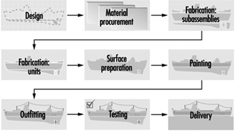
Newport News Shipbuilding
The basic component of ship building is steel plate. The plates are cut, shaped, bent or otherwise manufactured to the desired configuration specified by the design (see figure 2 and figure 3). Typically the plates are cut by an automatic flame cutting process to various shapes. These shapes may be then welded together to form I and T beams and other structural members (see figure 4).
Figure 2. Automatic flame cutting of steel plate in fabrication shop.
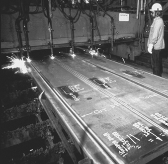
Eileen Mirsch
Figure 3. Bending of steel sheet.
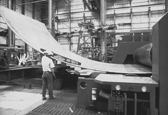
Newport News Shipbuilding
Figure 4. Welded steel plate forming part of a ship's hull.

Newport News Shipbuilding
The plates are then sent to fabrication shops, where they are joined into various units and subassemblies (see figure 5). At this juncture, piping, electrical and other utility systems are assembled and integrated into the units. The units are assembled using automatic or manual welding or a combination of the two. Several types of welding processes are employed. The most common is stick welding, in which a consumable electrode is used to join the steel. Other welding processes use inert gas shielded arcs and even non-consumable electrodes.
Figure 5. Working on a ship subassembly

Newport News Shipbuilding
The units or subassemblies are usually then transferred to an open-air platen or lay down area where erection, or joining of assemblies, occurs to form even larger units or blocks (see figure 6) Here, additional welding and fitting occurs. Further, the units and welds must undergo quality-control inspections and testing such as radiography, ultrasonic and other destructive or non-destructive tests. Those welds found defective must be removed by grinding, arc-air grouping or chiseling and then replaced. At this stage the units are abrasive blasted to ensure proper profiling, and painted (see figure 7. Paint may be applied by brush, roller or spray gun. Spraying is most commonly utilized. The paints may be flammable or toxic or pose an environmental threat. Control of abrasive blasting and painting operations must be performed at this time.
Figure 6. Combining of ship subassemblies into larger blocks
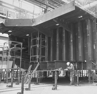
Newport News Shipbuilding
Figure 7. Abrasive blasting of ship units prior to painting.
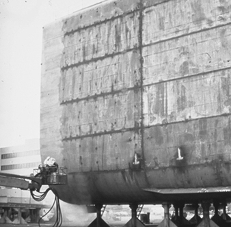
Judi Baldwin
The completed larger units are then moved to the graving dock, shipway or final assembly area. Here, the larger units are joined together to form the vessel (see figure 8) Again, much welding and fitting occur. Once the hull is structurally complete and watertight, the vessel is launched. This may involve sliding it into the water from the shipway on which it was constructed, flooding of the dock in which it was constructed or lowering the vessel into the water. Launchings are almost always accompanied by great celebration and fanfare.
Figure 8. Adding ship's bow to the rest of the vessel.
Newport News Shipbuilding
After the ship is launched, it enters the outfitting phase. A large amount of time and equipment are required. The work includes the fitting of cabling and piping, the furnishing of galleys and accommodations, insulation work, installation of electronic equipment and navigation aids and installation of propulsion and ancillary machinery. This work is performed by a wide variety of skilled trades.
After completion of the outfitting phase, the ship undergoes both dock and sea trials, during which all the ship’s systems are proved to be fully functional and operational. Finally, after all testing and associated repair work is performed, the ship is delivered to the customer.
Steel fabrication
A detailed discussion of the steel fabrication process follows. It is discussed in the context of cutting, welding and painting.
Cutting
The “assembly line” of the shipyard starts in the steel storage area. Here, large steel plates of various strengths, sizes, and thicknesses are stored and readied for fabrication. The steel is then blasted with abrasive and primed with a construction primer that preserves the steel during the various phases of construction. The steel plate then is transported to a fabrication facility. Here the steel plate is cut by automatic burners to the desired size (see figure 2). The resulting strips are then welded together to form the structural components of the vessel (figure 4).
Welding
The structural framework of most ships is constructed of various grades of mild and high-strength steel. Steel provides the formability, machinability and weldability required, combined with the strength needed for ocean-going vessels. Various grades of steel predominate in the construction of most ships, although aluminium and other nonferrous materials are used for some superstructures (e.g., deck-houses) and other specific areas within the ship. Other materials found on ships, like stainless steel, galvanized steel and copper-nickel alloy, are used for a variety of corrosion-resistance purposes and to improve structural integrity. However, nonferrous materials are used in far less quantity than steel. Shipboard systems (e.g., ventilation, combat, navigational and piping) are usually where the more “exotic” materials are used. These materials are required to perform a wide variety of functions, including the ship propulsion systems, back-up power, kitchens, pump stations for fuel transfer and combat systems.
Steel used for construction can be subdivided into three types: mild, high-strength and high-alloy steel. Mild steels have valuable properties and are easy to produce, purchase, form and weld. On the other hand, high-strength steels are mildly alloyed to provide mechanical properties that are superior to the mild steels. Extremely high-strength steels have been developed specifically for use in naval construction. In general, the high-strength and high-yield steels are called HY-80, HY-100 and HY-130. They have strength properties in excess of the commercial-grade high-strength steels. More complicated welding processes are necessary for high-strength steels in order to prevent deterioration of their properties. Specific weld rods are needed for high-strength steel, and weld joint heating (preheating) is usually required. A third general class of steels, the high-alloy steels, are made by including relatively large amounts of alloying elements such as nickel, chromium and manganese. These steels, which include stainless steels, have valuable corrosion-resistance properties and also require special welding processes.
Steel is an excellent material for shipbuilding purposes, and the choice of welding electrode is critical in all welding applications during construction. The standard goal is to obtain a weld with equivalent strength characteristics to that of the base metal. Since minor flaws are likely to occur in production welding, welds are often designed and welding electrodes chosen to produce welds with properties in excess of those of the base metal.
Aluminium has found increased application as a shipbuilding metal due to its high strength-to-weight ratio compared to steel. Although the use of aluminium for hulls has been limited, aluminium superstructures are becoming more common for both military and merchant ship construction. Vessels made solely from aluminium are primarily smaller-sized boats, such as fishing boats, pleasure boats, small passenger boats, gunboats and hydrofoils. The aluminium used for shipbuilding and repair is generally alloyed with manganese, magnesium, silicon and/or zinc. These alloys offer good strength, corrosion resistance and weldability.
Shipyard welding processes, or more specifically fusion welding, is performed at nearly every location in the shipyard environment. The process involves joining metals by bringing adjoining surfaces to extremely high temperatures to be fused together with a molten filler material. A heat source is used to heat the edges of the joint, permitting them to fuse with molten weld fill metal (electrode, wire or rod). The required heat is usually generated by an electric arc or a gas flame. Shipyards choose the type of welding process based on customer specifications, production rates and a variety of operating constraints including government regulations. Standards for military vessels are usually more stringent than commercial vessels.
An important factor with respect to the fusion-welding processes is arc shielding to protect the weld pool. The temperature of the weld pool is substantially higher than the adjoining metal’s melting point. At extremely high temperatures, a reaction with oxygen and nitrogen in the atmosphere is rapid and has negative effects on the weld strength. Should oxygen and nitrogen from the atmosphere become trapped within the weld metal and molten rod, embrittlement of the weld area will occur. To protect against this weld impurity and ensure weld quality, shielding from the atmosphere is required. In most welding processes, shielding is accomplished by addition of a flux, a gas or a combination of the two. Where a flux material is used, gases generated by vaporization and chemical reaction at the electrode tip result in a combination of flux and gas shielding that protect the weld from nitrogen and oxygen entrapment. Shielding is discussed in the following sections, where specific welding processes are described.
In electric arc welding, a circuit is created between the work-piece and an electrode or wire. When the electrode or wire is held a short distance away from the work-piece, a high-temperature arc is created. This arc generates sufficient heat to melt the edges of the work-piece and the tip of the electrode or wire to produce a fusion-welding system. There are a number of electric arc welding processes suitable for use in shipbuilding. All processes require shielding of the weld area from the atmosphere. They may be subdivided into flux-shielded and gas-shielded processes.
Manufacturers of welding equipment and associated consumable and non-consumable products report that arc welding with consumable electrodes is the most universal welding process.
Shielded metal arc welding (SMAW). Flux-shielded electric arc welding processes are distinguished primarily by their manual or semi-automatic nature and the type of consumable electrode used. The SMAW process utilizes a consumable electrode (30.5 to 46 cm in length) with a dry flux coating, held in a holder and fed to the work-piece by the welder. The electrode consists of the solid metal filler rod core, made from either drawn or cast material covered with a sheath of metal powders. SMAW is also frequently referred to as “stick welding” and “arc welding”. The electrode metal is surrounded by flux that melts as welding progresses, covering the deposited molten metal with slag and enveloping the immediate area in an atmosphere of protective gas. Manual SMAW may be used for down hand (flat), horizontal, vertical and overhead welding. SMAW processes may also be used semi-automatically through the use of a gravity welding machine. Gravity machines use the weight of the electrode and holder to produce travel along the work-piece.
Submerged arc welding (SAW) is another flux-shielded electric arc welding process used in many shipyards. In this process, a blanket of granulated flux is deposited on the work-piece, followed by a consumable bare metal wire electrode. Generally, the electrode serves as the filler material, although in some cases metal granules are added to the flux. The arc, submerged in the blanket of flux, melts the flux to produce a protective insulated molten shield in the weld zone. High heat concentration permits heavy weld deposits at relatively high speeds. After welding, the molten metal is protected by a layer of fused flux, which is subsequently removed and may be recovered. Submerged arc welding must be performed down hand and is ideally suited to butt welding plates together on panel lines, platen areas and erection areas. The SAW process is generally fully automatic, with equipment mounted on a moving carriage or self-propelled platform on top of the work-piece. Since the SAW process is primarily automatic, a good portion of time is spent aligning the weld joint with the machine. Similarly, since the SAW arc operates under a covering of granulated flux, the fume generation rate (FGR) or fume formation rate (FFR) is low and will remain constant under various operating conditions provided that there is adequate flux cover.
Gas metal arc welding (GMAW). Another major category of electric arc welding comprises the gas-shielded processes. These processes generally use bare wire electrodes with an externally supplied shielding gas which may be inert, active or a combination of the two. GMAW, also commonly referred to as metal inert gas (MIG) welding, uses a consumable, automatically fed, small-diameter wire electrode and gas shielding. GMAW is the answer to a long-sought method of being able to weld continuously without the interruption of changing electrodes. An automatic wire feeder is required. A wire spooling system provides an electrode/wire filler rate that is at a constant speed, or the speed fluctuates with a voltage sensor. At the point where the electrode meets the weld arc, argon or helium being used as the shielding gas is supplied by the welding gun. It was found that for welding steel, a combination of CO2 and/or an inert gas could be used. Often, a combination of the gases is used to optimize cost and weld quality.
Gas tungsten arc welding (GTAW). Another type of gas-shielded welding process is gas tungsten arc welding, sometimes referred to as tungsten inert gas (TIG) welding or the trade name Heliarc, because helium was initially used as the shielding gas. This was the first of the “new” welding processes, following stick welding by about 25 years. The arc is generated between the work-piece and a tungsten electrode, which is not consumed. An inert gas, usually argon or helium, provides the shielding and provides for a clean, low-fume process. Also, the GTAW process arc does not transfer the filler metal, but simply melts the material and the wire, resulting in a cleaner weld. GTAW is most often employed in shipyards for welding aluminium, sheet metal and small-diameter pipes and tubes, or to deposit the first pass on a multi-pass weld in larger pipe and fittings.
Flux core arc welding (FCAW) uses equipment similar to GMAW in that the wire is fed continuously to the arc. The main difference is that the FCAW electrode is a tubular electrode wire with a flux core centre that helps with localized shielding in the welding environment. Some flux cored wire provides adequate shielding with the flux core alone. However, many FCAW processes used in the shipbuilding environment require the addition of gas shielding for the quality requirements of the shipbuilding industry.
The FCAW process provides a high-quality weld with higher production rates and welder efficiency than the traditional SMAW process. The FCAW process allows for a full range of production requirements, such as overhead and vertical welding. FCAW electrodes tend to be a little more expensive than SMAW materials, although in many cases increased quality and productivity are worth the investment.
Plasma-arc welding (PAW). The last of the shielded gas welding processes is plasma-metal inert-gas welding. PAW is very similar to the GTAW process except that the arc is forced to pass through a restriction before reaching the work-piece. The result is a jet stream of intensely hot and fast-moving plasma. The plasma is an ionizing stream of gas that carries the arc, which is generated by constricting the arc to pass through a small orifice in the torch. PAW results in a more concentrated, high-temperature arc, and this permits faster welding. Aside from the use of the orifice to accelerate the gas, PAW is identical to GTAW, using a non-consumable tungsten electrode and an inert gas shield. PAW is generally manual and has minimal use in shipbuilding, although it is sometimes used for flame spraying applications. It is used primarily for steel cutting in the shipbuilding environment (see figure 9).
Figure 9. Underwater Plasma-arc cutting of steel plate
Caroline Kiehner
Gas welding, brazing and soldering. Gas welding employs heat generated by the burning of a gas fuel and generally uses a filler rod for the metal deposited. The most common fuel is acetylene, used in combination with oxygen (oxyacetylene gas welding). A hand-held torch directs the flame to the work-piece while simultaneously melting filler metal which is deposited on the joint. The surface of the work-piece melts to form a molten puddle, with filler material used to fill gaps or grooves. The molten metal, mainly filler metal, solidifies as the torch progresses along the work-piece. Gas welding is comparatively slow and not suitable for use with automatic or semiautomatic equipment. Consequently, it is rarely used for normal production welding in shipyards. The equipment is small and portable, and it can be useful for welding thin plate (up to about 7 mm), as well as for small-diameter pipe, heating, ventilating and air conditioning (HVAC) trunks (sheet metal), electrical cable ways and for brazing or soldering. Identical or similar equipment is used for cutting.
Soldering and brazing are techniques for bonding two metal surfaces without melting the parent metal. A liquid is made to flow into and fill the space between the two surfaces and then solidify. If the temperature of the filler metal is below 450ºC, the process is called soldering; if it is above 450ºC, the process is called brazing. Soldering is commonly done using heat from a soldering iron, flame, electrical resistance or induction. Brazing uses the heat from a flame, resistance or induction. Brazing may also be done by dipping parts in a bath. Soldered and brazed joints do not have the strength properties of welded joints. Consequently, brazing and soldering find limited application in shipbuilding and repair, except for primarily small-diameter pipe joints, sheet metal fabrication, small and infrequent joiner work and maintenance functions.
Other welding processes. There are additional types of welding that may be used in the shipyard environment in small quantities for a variety of reasons. Electroslag welding transfers heat through molten slag, which melts the work-piece and the filler metal. Although the equipment used is similar to that used for electric arc welding, the slag is maintained in a molten state by its resistance to the current passing between the electrode and the work-piece. Therefore, it is a form of electric resistance welding. Often a cooled backing plate is used behind the work-piece to contain the molten pool. Electrogas welding employs a similar setup but uses a flux-coated electrode and CO2 gas shielding. Both of these processes are very efficient for automatically making vertical butt welds and are highly advantageous for thicker plate. These techniques are expected to receive considerably wider application in shipbuilding.
Thermite welding is a process that uses superheated liquid metal to melt the work-piece and provided filler metal. The liquid metal results from a chemical reaction between a melt oxide and aluminium. The liquid metal is poured into the cavity to be welded, and the cavity is surrounded by a sand mould. Thermite welding is somewhat similar to casting and is primarily used to repair castings and forgings or to weld large structural sections such as a stern frame.
Laser welding is a new technology which uses a laser beam to melt and join the work-piece. Although the feasibility of laser welding has been proven, cost has prevented its commercial application to date. The potential for efficient, high-quality welding may make laser welding an important technique for shipbuilding in the future.
Another relatively new welding technique is called electron beam welding. The weld is made by firing a stream of electrons through an orifice to the work-piece, which is surrounded by an inert gas. Electron beam welding does not depend on thermal conductivity of the material to melt the metal. Consequently, both lower energy requirements and reduced metallurgical effects on the steel are significant benefits of this technique. As with laser welding, high cost is a major problem.
Stud welding is a form of electric arc welding in which the stud itself is the electrode. A stud welding gun holds the stud while the arc is formed and the plate and stud end become molten. The gun then forces the stud against the plate and the stud is welded to the plate. Shielding is obtained by the use of a ceramic ferrule surrounding the stud. Stud welding is a semi-automatic process commonly used in shipbuilding to facilitate installation of non-metallic materials, such as insulation, to steel surfaces.
Painting and finish coating
Painting is performed at almost every location in the shipyard. The nature of shipbuilding and repair requires several types of paints to be used for various applications. Paint types range from water-based coatings to high-performance epoxy coatings. The type of paint needed for a certain application depends on the environment to which the coating will be exposed. Paint application equipment ranges from simple brushes and rollers to airless sprayers and automatic machines. In general, shipboard paint requirements exist in the following areas:
- underwater (hull bottom)
- waterline
- topside superstructures
- internal spaces and tanks
- weather decks
- loose equipment.
Many different painting systems exist for each of these locations, but navy ships may require a specific type of paint for every application through a military specification (Mil-spec). There are many considerations when choosing paints, including environmental conditions, severity of environmental exposure, drying and curing times, applications equipment and procedures. Many shipyards have specific facilities and yard locations where painting occurs. Enclosed facilities are expensive, but yield higher quality and efficiency. Open-air painting generally has a lower transfer efficiency and is limited to good weather conditions.
Shipyard paint coating systems. Paints are used for a variety of purposes on a variety of locations on the ships. No one paint can perform all of the desired functions (e.g., rust prevention, anti-fouling and alkaline resistance). Paints are made up of three main ingredients: pigment, a vehicle and a solvent. Pigments are small particles that generally determine the colour as well as the many properties associated with the coating. Examples of pigments are zinc oxide, talc, carbon, coal tar, lead, mica, aluminium and zinc dust. The vehicle can be thought of as the glue that holds the paint pigments together. Many paints are referred to by their binder type (e.g., epoxy, alkyd, urethane, vinyl, phenolic). The binder is also very important for determining the coating’s performance characteristics (e.g., flexibility, chemical resistance, durability, finish). The solvent is added to thin the paint and allow for flowing application to surfaces. The solvent portion of the paint evaporates when the paint dries. Some typical solvents include acetone, mineral spirits, xylene, methyl ethyl ketone and water. Anticorrosive and anti-fouling paints are typically used on ships’ hulls and are the main two types of paint used in the shipbuilding industry. The anticorrosive paints are either vinyl-, lacquer-, urethane- or newer epoxy-based coating systems. The epoxy systems are now very popular and exhibit all of the qualities which the marine environment requires. Anti-fouling paints are used to prevent the growth and attachment of marine organisms on the hulls of vessels. Copper-based paints are widely used as anti-fouling paints. These paints release minute quantities of toxic substances in the immediate vicinity of the vessel’s hull. To achieve different colours, lampblack, red iron oxide or titanium dioxide may be added to the paint.
Shipyard primer coatings. The first coating system applied to raw steel sheets and parts is generally preconstruction primer, which is sometimes referred to as “shop primer”. This coat is important for maintaining the condition of the part throughout the construction process. Preconstruction priming is performed on steel plates, shapes, sections of piping and ventilation ducting. Shop primer has two important functions: (1) preserving the steel material for the final product and (2) aiding in the productivity of construction. Most preconstruction primers are zinc rich, with organic or inorganic binders. Zinc silicates are predominant among the inorganic zinc primers. Zinc coating systems protect coatings in much the same manner as galvanizing. If zinc is coated on steel, oxygen will react with the zinc to form zinc oxide, which forms a tight layer that does not allow water and air to come into contact with the steel.
Paint-applying equipment. There are many types of paint application equipment used in the shipbuilding industry. Two common methods used are compressed-air and airless sprayers. Compressed-air systems spray both air and paint, which causes some paint to atomize (dry) quickly prior to reaching the intended surface. The transfer efficiency of air-assisted spray systems can vary from 65 to 80%. This low transfer efficiency is due mainly to overspray, drift and the air sprayer’s inefficiencies; these sprayers are becoming obsolete because of their low transfer ability.
The most widely used form of paint application in the shipbuilding industry is the airless sprayer. The airless sprayer is a system which simply compresses paint in a hydraulic line and has a spray nozzle at the end; hydrostatic pressure, instead of air pressure, conveys the paint. To reduce the amount of overspray and spillage, shipyards are maximizing the use of airless paint sprayers. Airless sprayers are much cleaner to operate and have fewer leaking problems than compressed-air sprayers because the system requires less pressure. Airless sprayers have close to 90% transfer efficiency, depending on the conditions. A new technology which can be added to the airless sprayer is called high volume, low pressure (HVLP). HVLP offers an even higher transfer efficiency, in certain conditions. Measurements of transfer efficiency are estimates and include allowances for drips and spills which can occur when painting.
Thermal spray, also known as metal or flame spray, is the application of aluminium or zinc coatings to steel for long-term corrosion protection. This coating process is used on a wide variety of commercial and military applications. It is significantly different from conventional coating practices due to its specialized equipment and relatively slow production rates. There are two basic types of thermal coating machines: combustion wire and arc spray. The combustion wire type consists of combustible gases and a flame system with a wire feed controller. The combustible gases melt the material to be sprayed onto the parts. The electric arc spray machine instead uses a power supply arc to melt the flame sprayed material. This system includes an air-compression and filtration system, a power arc supply and controller and an arc flame spray gun. The surface must be properly prepared for proper adhesion of flame sprayed materials. The most common surface preparation technique is air blasting with fine grit (e.g., aluminium oxide).
The initial cost of thermal spray is usually high compared to painting, although when the lifecycle is taken into account, thermal spray becomes more economically attractive. Many shipyards have their own thermal spray machines, and other shipyards will subcontract their thermal coating work. Thermal spray can be done in a shop or on board the ship.
Painting practices and methods. Painting is performed in nearly every area in the shipyard, from the initial priming of the steel to the final paint detailing of the ship. Methods for painting vary greatly from process to process. Mixing of paint is performed both manually and mechanically and is usually done in an area surrounded by berms or secondary containment pallets; some of these are covered areas. Outdoor as well as indoor painting occurs in the shipyard. Shrouding fences, made of steel, plastic or fabric, are frequently used to help contain paint overspray or to block the wind and catch paint particles. New technology will aid in reducing the amount of airborne particles. Reducing the amount of overspray also reduces the amount of paint used and thus saves the shipyard money.
Surface preparation and painting areas in the shipyard
To illustrate painting and surface preparation practices in the shipbuilding and repair industry, practices can be generically described in five main areas. The following five areas help to illustrate how painting occurs in the shipyard.
Hull painting. Hull painting occurs on both repair ships and new construction ships. Hull surface preparation and painting on repair ships is normally performed when the ship is fully drydocked (i.e., on the graving dock of a floating drydock). For new construction, the hull is prepared and painted at a building position using one of the techniques discussed above. Air and/or water blasting with mineral grit are the most common types of surface preparation for hulls. Surface preparation involves blasting the surface from platforms or lifts. Similarly, paint is applied using sprayers and high-reach equipment such as man-lifts, scissor lifts or portable scaffolding. Hull painting systems vary in the number of coats required.
Superstructure painting. The superstructure of the ship consists of the exposed decks, deck houses and other structures above the main deck. In many cases, scaffolding will be used on board the ship to reach antennas, houses and other superstructures. If it is likely that paint or blast material will fall into adjacent waters, shrouding is put into place. On ships being repaired, the ship’s superstructure is painted mostly while berthed. The surface is prepared using either hand tools or air-nozzle blasting. Once the surface is prepared and the associated surface materials and grit are cleaned up and disposed of, then painting can commence. Paint systems usually are applied with airless paint sprayers. The painters access the superstructures with existing scaffolding, ladders and various lifting equipment that was used during surface preparation. The shrouding system (if applicable) that was used for blast containment will stay in place to help contain any paint overspray.
Interior tank and compartment painting. Tanks and compartments on board ships must be coated and re-coated to maintain the longevity of the ship. Re-coating of repair ship tanks requires a large amount of surface preparation prior to painting. The majority of the tanks are at the bottom of the ship (e.g., ballast tanks, bilges, fuel tanks). The tanks are prepared for paint by using solvents and detergents to remove grease and oil build-up. The wastewater developed during tank cleaning must be properly treated and disposed of. After the tanks are dried, they are abrasive blasted. During the blasting operation, the tank must have recirculating air and the grit must be vacuumed out. The vacuum systems used are either of a liquid ring or rotary screw type. These vacuums must be very powerful to remove the grit from the tank. The vacuum systems and ventilation systems are generally located on the dock’s surface, and access to the tanks is through holes in the hull. Once the surface is blasted and the grit is removed, painting can begin. Adequate ventilation and respirators are required for all tank and compartment surface preparation and painting (i.e., in enclosed or confined spaces).
Paint surface preparation as stages of construction. Once the blocks, or multiple units, leave the assembly area, they are frequently transported to a blast area where the entire block is prepared for paint. At this point, the block is usually blasted back down to bare metal (i.e., the construction primer is removed) (see figure 7 ). The most frequent method for block surface preparation is air-nozzle blasting. The next stage is the paint application stage. Painters generally use airless spray equipment on access platforms. Once the block’s coating system has been applied, the block is transported to the on-block stage, where outfitting materials are installed.
Small parts painting areas. Many parts comprising a ship need to have a coating system applied to them prior to installation. For example, piping spools, vent ducting, foundations and doors are painted before they are installed on block. Small parts are generally prepared for paint in a designated area of the shipyard. Small parts painting can occur in another designated location in the shipyard that best matches production needs. Some small parts are painted in the various shops, while others are painted in a standard location operated by the paint department.
Surface preparation and painting on block and on board
Final painting of the ship occurs on board, and touch-up painting will frequently occur on block (see figure 10). On-block touch-up painting occurs for several reasons. In some cases, paint systems are damaged on block and need to be resurfaced, or perhaps the wrong paint system was applied and needs to be replaced. On-block painting involves using portable blasting and painting equipment throughout the on-block outfitting areas. On-board painting involves preparing and painting the interface sections between the construction blocks and repainting areas damaged by welding, rework, on-board outfitting and other processes. The surfaces can be prepared by hand tools, sanding, brushing, solvent cleaning or any of the other surface preparation techniques. Paint is applied with portable airless sprayers, rollers and brushes.
Figure 10. Touch-up painting on a ship's hull.
Newport News Shipbuilding
Outfitting
Pre-erection outfitting of construction blocks is the current shipbuilding method used by all competitive shipbuilders worldwide. Outfitting is the process of installing parts and various subassemblies (e.g., piping systems, ventilation equipment, electrical components) on the block prior to joining the blocks together at erections. The outfitting of blocks throughout the shipyard lends itself to forming an assembly line approach to shipbuilding.
Outfitting at each stage of construction is planned to make the process flow smoothly throughout the shipyard. For simplicity, outfitting can be divided into three main stages of construction once the steel structure of the block has been assembled:
- unit outfitting
- on-block outfitting
- on-board outfitting.
Unit outfitting is the stage where fittings, parts, foundations, machinery and other outfitting materials are assembled independent of the hull block (i.e., units are assembled separate from steel structural blocks). Unit outfitting allows workers to assemble shipboard components and systems on the ground, where they have easy access to the machinery and workshops. Units are installed at either the on-board or the on-block stage of construction. Units come in varying sizes, shapes and complexities. In some cases, units are as simple as a fan motor connected to a plenum and coil. Large, complex units are mainly composed of components in machinery spaces, boilers, pump rooms and other complex areas of the ship. Unit outfitting involves assembling piping spools and other components together, then connecting the components into units. Machinery spaces are areas on the ship where machinery is located (e.g., engine rooms, pump stations and generators) and outfitting there is intensive. Outfitting units on the ground increases safety and efficiency by reducing the work hours that would otherwise be allocated to on-block or on-board work in more confined spaces where conditions are more difficult.
On-block outfitting is the stage of construction where most of the outfitting material is installed onto the blocks. Outfitting materials installed on block consist of ventilation systems, piping systems, doors, lights, ladders, railings, electrical assemblies and so on. Many units are also installed at the on-block stage. Throughout the on-block outfitting stage, the block can be lifted, rotated and moved to efficiently facilitate installing outfitting materials on the ceilings, walls and floors. All of the shops and services in the shipyard must be in communication at the on-block stage to ensure that materials are installed at the right time and place.
On-board outfitting is performed after the blocks are lifted onto the ship under construction (i.e., after erection). At this time, the ship is either at a building position (building ways or building dock), or the ship could be berthed at pierside. The blocks are already outfitted to a large extent, although much more work is still needed before the ship is ready to operate. On-board outfitting involves the process of installing large units and blocks on board the ship. Installation includes lifting the large blocks and units on board the new ship and welding or bolting them into place. On-board outfitting also involves connecting the shipboard systems together (i.e., piping system, ventilation system and electrical system). All of the wiring systems are pulled throughout the ship at the on-board stage.
Testing
The operation and test stage of construction assesses the functionality of installed components and systems. At this stage, systems are operated, inspected and tested. If the systems fail the tests for any reason, the system must be repaired and retested until it is fully operational. All piping systems on board the ship are pressurized to locate leaks that may exist in the system. Tanks also need structural testing, which is accomplished by filling the tanks with fluids (i.e., salt water or fresh water) and inspecting for structural stability. Ventilation, electrical and many other systems are tested. Most system testing and operations occur while the ship is docked at pierside. However, there is an increasing trend to perform testing at earlier stages of construction (e.g., preliminary testing in the production shops). Performing tests at earlier stages of construction makes it easier to fix failures because of the increased accessibility to the systems, although complete systems tests will always need be done on board. Once all preliminary pierside testing is performed, the ship is sent to sea for a series of fully operational tests and sea trials before the ship is delivered to its owner.
Ship Repair
Steel ship repair practices and processes
Ship repair generally includes all ship conversions, overhauls, maintenance programmes, major damage repairs and minor equipment repairs. Ship repair is a very important part of the shipping and shipbuilding industry. Approximately 25% of the labour force in most private shipbuilding shipyards does repair and conversion work. Currently there are many ships that need updating and/or conversions to meet safety and environmental requirements. With fleets worldwide becoming old and inefficient, and with the high cost of new ships, the situation is putting a strain on shipping companies. In general, conversion and repair work in US shipyards is more profitable than new construction. In new-construction shipyards, repair contracts, overhauls and conversions also help to stabilize the workforce during times of limited new construction, and new construction augments the repair labour workload. The ship repair process is much like the new construction process, except that it is generally on a smaller scale and is performed at a faster pace. The repair process requires a more timely coordination and an aggressive bidding process for ship repair contracts. Repair work customers are generally the navy, commercial ship owners and other marine structure owners.
The customer usually provides contract specifications, drawings and standard items. Contracts can be firm fixed price (FFP), firm fixed price award fee (FFPAF), cost plus fixed fee (CPFF), cost plus award fee (CPAF) or urgent repair contracts. The process starts in the marketing area when the shipyard is asked for a request for proposal (RFP) or an invitation for bid (IFB). The lowest price usually wins an IFB contract, while a RFP award can be based on factors other than price. The repair estimating group prepares the cost estimate and the proposal for the repair contract. Bid estimates generally include worker-hours and wage rates, materials, overhead, special service costs, subcontractor dollars, overtime and shift premiums, other fees, facilities cost of money and, based on these, the estimated price of the contract. Once the contract is awarded, a production plan must be developed.
Repair planning, engineering and production
Although some preliminary planning is performed at the proposal stage of the contract, much work is still needed to plan and execute the contract in a timely manner. The following steps should be accomplished: read and understand all contract specifications, categorize the work, integrate the work into a logical production plan and determine the critical path. Planning, engineering, materials, subcontracts and repair production departments must work closely together to perform the repair in the most timely and cost-effective manner. Prefabrication of piping, ventilation, electrical and other machinery is performed, in many cases, prior to the ship’s arrival. Pre-outfitting and prepackaging of repair units takes cooperation with the production shops to perform work in a timely manner.
Common types of repair work
Ships are similar to other types of machinery in that they require frequent maintenance and, sometimes, complete overhauls to remain operational. Many shipyards have maintenance contracts with shipping companies, ships and/or ship classes that identify frequent maintenance work. Examples of maintenance and repair duties include:
- blasting and repainting the ship’s hull, freeboard, superstructure, interior tanks and work areas
- major machinery rebuilding and installation (e.g., diesel engines, turbines, generators and pump stations)
- systems overhauls, maintenance and installation (e.g., flushing, testing and installation of a piping system)
- new system installation, either adding new equipment or replacing systems that are outdated (e.g., navigational systems, combat systems, communication systems or updated piping systems)
- propeller and rudder repairs, modification and alignment
- creation of new machinery spaces on the ship (e.g., cut-out of existing steel structure and adding new walls, stiffeners, vertical supports and webbing).
In many cases, repair contracts are an emergency situation with very little warning, which makes ship repair a fast moving and unpredictable environment. Normal repair ships will stay in the shipyard from 3 days to 2 months, while major repairs and conversions can last more than a year
Large repairs and conversion projects
Large repair contracts and major conversions are common in the ship repair industry. Most of these large repair contracts are performed by shipyards that have the ability to construct ships, although some primarily repair yards will perform extensive repairs and conversions.
Examples of major repair contracts are as follows:
- conversion of supply ships to hospital ships
- cutting a ship in half and installing a new section to lengthen the ship (see figure 11)
- replacing segments of a ship that has run aground (see figure 12)
- complete rip-out, structural reconfiguration and outfitting of combat systems
- major remodelling of ship’s interior or exterior (e.g., complete overhauls of passenger cruise ships).
Most major repairs and conversions require a large planning, engineering and production effort. In many cases, a large quantity of steel work will need to be accomplished (e.g., major cut-out of existing ship structure and installation of new configurations). These projects can be divided into four major stages: removal, building new structure, equipment installation and testing. Subcontractors are required for most major and minor repairs and conversions. The subcontractors provide expertise in certain areas and help to even the workload in the shipyard.
Figure 11. Cutting a ship in half in order to install a new section.

Newport News Shipbuilding
Figure 12. Replacing the prow of a ship that ran aground.
Newport News Shipbuilding
Some of the work that subcontractors perform are as follows:
-
support of ship repair
-
major combat systems installations (technical)
-
boiler re-tubing and rebuilding
-
air compressor overhauls
-
asbestos removal and disposal
-
tank cleaning
-
blasting and painting
-
pump system overhauls
-
small structural fabrication
-
winch overhauls
-
main steam system modifications
-
system fabrications (i.e., piping, ventilation, foundations and so on).
As with new construction, all installed systems must be tested and operational before the ship is returned to its owner. Testing requirements generally originate from the contract, although other sources of testing requirements do exist. The tests must be scheduled, tracked for proper completion and monitored by the proper groups (shipyard internal quality, vessel operation, government agencies, shipowners and so on). Once systems are in place and properly tested, the area, compartment and/or system can be considered sold to the ship (i.e., completed).
There are many similarities between new construction and repair processes. The primary similarities are that they both use the application of essentially the same manufacturing practices, processes, facilities and support shops. Ship repair and new construction work require highly skilled labour because many of the operations have limited potential for automation (especially ship repair). Both require excellent planning, engineering and interdepartmental communications. The repair process flow is generally as follows: estimate, plan and engineer the job; rip-out work; refitting of steel structures; repair production; test and trials; and deliver the ship. In many ways the ship repair process is similar to shipbuilding, although new construction requires a greater amount of organization because of the size of the workforce, size of the workload, number of parts and the complexity of the communications (i.e., production plans and schedules) surrounding the shipbuilding work flow.
Hazards and Precautions
Shipbuilding and repair is one of the most hazardous industries. Work must be done in a variety of highly hazardous situations, such as confined spaces and considerable heights. Much manual work is performed involving heavy equipment and material. Since the work is so interrelated, the results of one process may endanger personnel involved in another process. In addition, a great portion of work is performed out-of-doors, and the effects of weather extremes can cause or aggravate hazardous conditions. Additionally, a number of chemicals, paints, solvents and coatings must be used, which may pose significant risks to employees.
Health hazards
Chemical hazards which pose health risks to employees in shipyards include:
- dusts from abrasive blasting operations
- exposure to asbestos and mineral fibres in insulation work
- vapours and spray mists from paints, coatings, solvents and thinners
- fumes from various welding, burning, soldering and brazing operations
- exposure to gases used in various welding, burning and heating processes
- exposure to specific toxic chemicals in epoxy resins, organo-tin and copper anti-fouling paints, lead paint, oils, greases, pigments and the like.
Physical hazards due to the manual nature of the work include:
- temperature and weather extremes associated with work performed out-of-doors
- electrical hazards
- ergonomic-related problems caused by repetitive handling of large and bulky materials
- ionizing and non-ionizing radiation
- noise and vibration
- oxygen deficiency potential and other confined space hazards associated with tanks, double bottoms and so on
- falls and trips from work on the same level as well as work from great heights.
Preventive measures
Although shipbuilding and repair is a very hazardous industry, the risks to personnel by these hazards can and should be minimized. The basis for hazard reduction is a well-founded health and safety programme that is rooted in a good partnership between management and the trade unions or employees. There are a number of approaches that can be utilized to prevent or minimize hazards in shipyards once they are identified. These approaches may be broadly divided into several strategies. Engineering controls are employed to eliminate or control hazards at their point of generation. These controls are the most desirable of the various types since they are most dependable:
-
Substitution or elimination. Where possible, processes that produce hazards or toxic materials should be eliminated or replaced with less hazardous processes or materials. This is the most effective form of control. An example is the use of non-carcinogenic materials instead of asbestos insulation. Another example is the use of hydraulic lifting tables for handling heavy materials, instead of manual lifting. Replacement of solvent-based paints with water-based coatings is frequently possible. Automation or robotics can be used to eliminate process hazards.
-
Isolation. Processes that are not amenable to substitution or elimination can sometimes be isolated from employees to minimize exposures. Frequently, sources of high noise can be relocated to place more distance between workers and the noise source, thus reducing exposure.
-
Enclosure. Processes or personnel can sometimes be enclosed to eliminate or reduce exposures. Operators of equipment can be provided enclosed booths to minimize exposure to noise, heat, cold or even chemical hazards. Processes may also be enclosed. Paint-spray booths and welding booths are examples of process enclosure that reduce exposures to potentially toxic materials.
-
Ventilation. Processes that produce toxic materials can be ventilated to capture the materials at their point of generation. This technique is used extensively in shipyards and boatyards, particularly to control welding fumes and gases, paint vapours and the like. Many fans and blowers are located on the decks of vessels and air is either exhausted from or blown into spaces to reduce exposure to hazards. Frequently fans are used in the blowing mode to direct fresh air into compartments to maintain acceptable oxygen levels.
Administrative controls are used to minimize exposures by administratively limiting the time spent by personnel in potentially hazardous situations. This is generally accomplished by rotating personnel from a relatively low hazard job to a higher hazard one. Although the aggregate amount of person-exposure time is not changed, exposure of each individual worker is reduced.
Administrative controls are not without their negative aspects. This technique requires additional training since workers must know both jobs and more workers are potentially exposed to a hazard. Also, since the number of personnel exposed to hazards has doubled from a legal standpoint, potential liabilities may be increased. However, administrative control can be an effective method if properly applied.
Personal protective controls. Shipyards must rely heavily on the various forms of personal protection. The nature of ship construction and repair does not lend itself to traditional engineering approaches. Ships are very confined spaces with limited access. A submarine under repair has 1 to 3 hatches that are .76 m in diameter, through which people and equipment must pass. The amount of ventilation tubing that can pass through is severely limited. Similarly, on large ships work is performed deep within the vessel, and although some ventilation may be smoked through the various levels to reach the desired operation, the amount is limited. Further, the fans pushing or pulling air through the vent tubing are generally located in fresh air, usually on a main deck, and they, too, have somewhat limited capacity.
In addition, ship construction and repair is not performed in an assembly line, but in separate work sites such that stationary engineering controls are impractical. Further, a ship may be under repair for a few days, and the extent to which engineering control may be utilized is again limited. Personal protective equipment is used extensively in these situations.
In shops, more extensive use may be made of traditional engineering control approaches. Most equipment and machinery in shops and assembly platens is very amenable to traditional guarding, ventilation and other engineering approaches. However, some personal protective equipment must be utilized in these situations as well.
A discussion of the various applications of personal protective equipment utilized in shipyards follows:
Welding, cutting and grinding. The basic process of constructing and repairing ships involves cutting, shaping and joining steel and other metals. In the process, metallic fumes, dusts and particulates are generated. Although ventilation can sometimes be utilized, more frequently welders must utilize respirators for protection from welding particulates and fumes. In addition, they must employ appropriate eye protection for ultraviolet and infrared illumination and other physical eye and face hazards. In order to provide protection from sparks and other forms of molten metal, the welder must be protected by welding gloves, long-sleeved clothing and other physical protection.
Abrasive blasting and painting. Much painting is performed in ship construction and repair. In many cases, the paints and coatings are specified by the ship’s owner. Prior to painting, the equipment must be blasted with an abrasive to a certain profile that ensures good adhesion and protection.
Abrasive blasting of small parts may be performed in a closed system such as a glove box. However, most large components are abrasive blasted manually. Some blasting is performed in the open air, some in large bays of a building or shop designated for this purpose and some inside the vessels or vessel sections themselves. In any case, personnel performing abrasive blasting must use full-body protection, hearing protection and air-fed respiratory protection. They must be provided with an adequate supply of breathable air (i.e., at least Grade D breathing air).
In some countries the use of crystalline silica has been banned. Its use is generally not recommended. If silica-containing materials are used in blasting, preventive protective measures must be taken.
After abrasive blasting, materials must be quickly painted in order to prevent “flash rusting” of the surface. Although mercury, arsenic and other very toxic metals are no longer used in paints, paints used in shipyards generally contain solvents as well as pigments such as zinc. Other paints are of the epoxy type. Painters who apply these coatings must be protected. Most painters must use a negative or positive pressure respirator for their protection, as well as full-body coveralls, gloves, shoe covers and eye protection. Sometimes painting must be performed in confined or enclosed spaces. In these cases, air-supplied respiratory protection and full-body protection must be used, and there must be an adequate, permit-requiring confined-spaces programme.
Overhead hazards. Shipyards have many cranes, and a large amount of overhead work is performed. Hard-hat protection is generally required in all production areas of shipyards.
Insulation work. Piping systems and other components must be insulated to maintain component temperature and reduce heat in the ship’s interior; in some cases, insulation is needed for noise reduction. In ship repair, existing insulation must be removed from piping to do repair work; in these cases, asbestos material is frequently encountered. In new work, fibreglass and mineral fibres are frequently used. In either case, appropriate respiratory protection and full-body protection must be worn.
Noise sources. Work in shipyards is notoriously noisy. Most processes involve working with metal; this typically produces noise levels above acceptable safe limits. Not all noise sources can be controlled to safe levels by utilizing engineering controls. Thus, personal protection must be used.
Foot hazards. Shipyards have a number of operations and processes that present hazards to the feet. It is often difficult and impractical to segregate the facility into foot hazard and non-foot hazard areas; safety shoes/boots are typically required for the entire production area of shipyards.
Eye hazards. There are many potential sources of hazards to the eyes in shipyards. Examples are various ultraviolet and infrared light hazards from welding arcs, physical hazards from various metal working dusts and particles, abrasive blasting grit, work with various pickling and metal baths, caustics and paint sprays. Due to the ubiquitous nature of these hazards, safety glasses are frequently required throughout the production areas of shipyards for practical and administrative simplicity. Special eye protection is required for specific individual processes.
Lead. Over the years, lead-based primers and coatings have been utilized extensively in ship construction. Although lead-containing paints and coatings are rarely used today, a significant amount of elemental lead is used in nuclear shipyards as a radiation shielding material. In addition, ship repair work often involves the removal of older coatings that frequently contain lead. In fact, repair work requires a great deal of sensitivity and concern for materials that have been applied or used previously. Work with lead requires full-body protection including coveralls, gloves, hat, shoe covers and respiratory protection.
Boat Building
In some ways boats can be thought of as relatively small ships in that many of the processes used to construct and repair boats are very similar to those used to construct and repair ships, only on a smaller scale. Generally, steel, wood and composites are chosen for construction of boat hulls.
Composites include, in general, such materials as fibre-reinforced metals, fibre-reinforced cement, reinforced concrete, fibre-reinforced plastics and glass-reinforced plastics (GRPs). Development during the early 1950s of hand lay-up methods employing cold-cure polyester resin with glass reinforcement led to a rapid expansion of GRP boat construction, from 4% in the 1950s to over 80% in the 1980s and even higher currently.
In vessels over 40 m or so in length, steel rather than wood is the main alternative to GRP. As hull size is reduced, the relative cost of steel construction increases, becoming generally uncompetitive for hulls under 20 m in length. The need for corrosion margin tends also to lead to excessive weight in small steel boats. For vessels over 40 m, however, the low cost of heavy welded steel construction is normally a decisive advantage. Unless imaginative design, improved materials and automated fabrication can bring about a substantial reduction in costs, however, glass- or fibre-reinforced plastics seem unlikely to become competitive with steel for construction of ships over about 40 m in length except where special requirements exist (e.g., for transportation of corrosive or cryogenic bulk cargo, where a nonmagnetic hull is required or where substantial weight saving is necessary for performance reasons).
GRPs are now employed in a very wide range of boat hull applications including speedboats, coastal and ocean-going yachts, work boats, pilot and passenger launches and fishing boats. Its success in fishing boats, where wood has been the traditional material, is attributable to:
-
competitive first cost, particularly where many hulls are built to the same design, enhanced by the increasing cost of wood and scarcity of skilled woodworkers
-
trouble-free performance and low maintenance costs resulting from leak-proof, rot-proof qualities of GRP hulls, their resistance to marine boring organisms and low cost of repair
-
the ease with which complex shapes, which may be required for hydrodynamic and structural purposes or for aesthetic reasons, can be fabricated.
Fabrication methods
The most common form of construction for shells, decks and bulkheads in large and small GRP hulls is single-skin laminate reinforced as necessary by stiffeners. Various methods of fabrication are employed in the construction of single-skin and sandwich hulls.
Contact moulding. By far the most common method of fabrication for single-skin GRP hulls of all sizes is contact moulding in an open or negative mould using cold-curing polyester resin and E-glass reinforcement.
The first step in the fabrication process is mould preparation. For hulls of small and moderate size, moulds are usually fabricated in GRP, in which case a positive plug, commonly of wooden construction finished in GRP, is first assembled, whose external surface accurately defines the required hull shape. Mould preparation is generally completed by wax polishing and application of a film of polyvinyl alcohol (PVA) or equivalent release agent. Laminating is usually started by application of pigmented gel coat of good-quality resin. Laminating is then continued, before the gel coat has fully cured, using one of the following processes:
-
Spray up. Glass fibre rovings or reinforcements are sprayed simultaneously with polyester resin, the latter being mixed with catalyst and accelerator at the spray gun.
-
Hand lay-up. Resin mixed with catalyst and accelerator is deposited liberally on the gel coat or on a previous ply of impregnated reinforcement by brush, roller-dispenser or spray gun.
The process outlined above can achieve efficient application of very heavy reinforcement (fabric of up to 4,000 g/m2 has been used successfully, although for large-scale production a fabric weight of 1,500 to 2,000 g/m2 has been preferred), giving a rapid laminating rate with low labour costs. A similar process can be applied for rapid lay-up of flat or nearly flat deck and bulkhead panels. Batch production of certain 49 m hulls, including installation of decks and bulkheads, has been achieved with a completion time of 10 weeks per hull.
Compression moulding. Compression moulding involves application of pressure, possibly accompanied by heat, to the surface of an uncured laminate, to increase fibre content and reduce voids by squeezing out excess resin and air.
Vacuum bag moulding. This process, which may be regarded as an elaboration of contact moulding, involves placing over the mould a flexible membrane, separated from the uncured laminate by a film of PVA, polythene or equivalent material, sealing the edges and evacuating the space under the membrane so that the laminate is subjected to a pressure of up to l bar. Curing may be speeded by placing the bagged component in an oven or employing a heated mould.
Autoclave moulding. Higher pressures (e.g., 5 to 15 bar) combined with elevated temperature, yielding increased fibre content and hence superior mechanical properties, may be achieved by carrying out the bag moulding process in an autoclave (pressurized oven).
Matched die moulding. The uncured moulding material, which in a large component such as a boat hull is likely to be a sprayed premix of resin and chopped-strand glass or a tailored preform of pre-impregnated glass fabric, is compressed between matched positive and negative moulds, usually of metallic construction, with application of heat if required. Because of the high first cost of moulds, this process is likely to be economical only for large production runs and is rarely used for boat hull fabrication.
Filament winding. Fabrication in this process is carried out by winding reinforcing fibres, in the form of a continuous roving which may be impregnated with resin just prior to winding (wet-winding) or may be pre-impregnated with partially cured resin (dry-winding), onto a mandrel which defines the internal geometry.
Sandwich construction. Sandwich hulls, decks and bulkheads may be fabricated by contact moulding, using room-temperature curing polyester resin, in much the same way as single-skin structures. The outer GRP skin is first laid up on the negative mould. Strips of core material are embedded on a layer of polyester or epoxy resin. Fabrication is then completed by laying up the internal GRP skin.
Polyester and epoxy resins. Unsaturated polyester resins are by far the most commonly used matrix materials for marine structural laminates. Their effectiveness follows from their moderate cost, ease of use within hand lay-up or spray-up fabrication processes and generally good performance in a marine environment. Three main types are available:
-
Orthophthalic polyester, made by a combination of maleic and phthalic anhydrides with a glycol (commonly propylene glycol), is the least expensive and most widely used matrix material for small boat construction.
-
Isophthalic polyester, containing isophthalic acid in place of phthalic anhydride, is more expensive, has somewhat superior mechanical properties and water resistance and is commonly specified for higher-performance boat construction and marine gel coats.
-
Bisphenol epoxy systems, in which phthalic acid or anhydride is partly or completely replaced by bisphenol A, offers (at substantially higher cost) much improved water and chemical resistance.
Safety and health hazards
Although many of the chemical, physical and biological hazards in shipbuilding are common to boat building, a primary concern is exposure to various solvent vapours and epoxy dusts from the boat manufacturing process. Uncontrolled exposure to these hazards may produce central nervous system disorders, liver and kidney damage, and sensitization reactions, respectively. The controls for these potential hazards are essentially the same as those described previously in the shipbuilding section—namely, engineering controls, administrative controls and personal protective controls.
" DISCLAIMER: The ILO does not take responsibility for content presented on this web portal that is presented in any language other than English, which is the language used for the initial production and peer-review of original content. Certain statistics have not been updated since the production of the 4th edition of the Encyclopaedia (1998)."