Control devices and devices used for isolating and switching must always be discussed in relation to technical systems, a term used in this article to include machines, installations and equipment. Every technical system fulfils a specific and assigned practical task. Appropriate safety control and switching devices are required if this practical task is to be workable or even possible under safe conditions. Such devices are used in order to initiate control, interrupt or retard the current and/or the impulses of electric, hydraulic, pneumatic and also potential energies.
Isolation and Energy Reduction
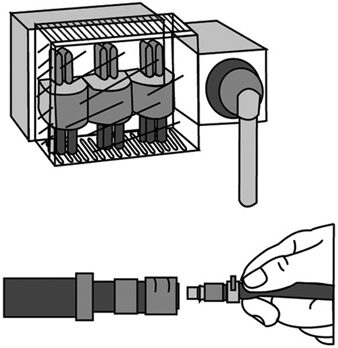
Isolating devices are used to isolate energy by disconnecting the supply line between the energy source and the technical system. The isolating device must normally yield an unequivocally determinable actual disconnection of the energy supply. Disconnection of the energy supply should also always be combined with the reduction of energy stored in all parts of the technical system. If the technical system is fed by several energy sources, all these supply lines must be capable of being reliably isolated. Persons trained to handle the relevant type of energy and who work at the energy end of the technical system, use isolation devices to shield themselves from the hazards of the energy. For safety reasons, these persons will always check to assure that no potentially hazardous energy remains in the technical system—for instance, by ascertaining the absence of electrical potential in the case of electric energy. Risk-free handling of certain isolating devices is possible only for trained specialists; in such cases, the isolating device must be made inaccessible to unauthorized persons. (See figure 1.)
Figure 1. Principles of electric and pneumatic isolating devices
The Master Switch
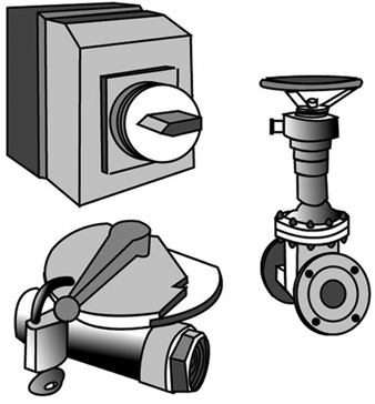
A master-switch device disconnects the technical system from the energy supply. Unlike the isolating device, it can be operated without danger even by “non-energy specialists”. The master- switch device is used to disconnect technical systems not in use at a given moment should, say, their operation be obstructed by unauthorized third persons. It is also used to effect a disconnection for such purposes as maintenance, repair of malfunctions, cleaning, resetting and refitting, provided that such work can be done without energy in the system. Naturally, when a master-switch device also possesses the characteristics of an isolating device, it can also take on and/or share its function. (See figure 2.)
Figure 2. Sample illustration of electric and pneumetic master-switch devices
Safety-disconnection Device
A safety-disconnection device does not disconnect the entire technical system from the energy source; rather, it removes energy from the parts of the system critical to a particular operational subsystem. Interventions of short duration can be designated for operational subsystems—for instance, for the set-up or resetting/refitting of the system, for the repair of malfunctions, for regular cleaning, and for essential and designated movements and function sequences required during the course of set-up, resetting/refitting or test runs. Complex production equipment and plants cannot simply be shut off with a master-switch device in these cases, as the entire technical system could not start up again where it left off after a malfunction has been repaired. Furthermore, the master-switch device is rarely located, in the more extensive technical systems, at the place where the intervention must be made. Thus the safety disconnection device is obliged to fulfil a number of requirements, such as the following:
- It interrupts the energy flow reliably and in such a way that dangerous movements or processes are not triggered by control signals which are either erroneously entered or erroneously generated.
- It is installed precisely where interruptions must be made in danger areas of operational subsystems of the technical system. If necessary, installation can be in several places (for instance, on various floors, in various rooms, or at various access points on machinery or equipment).
- Its control device has a clearly marked “off” position which registers only once after the flow of energy has been reliably cut off.
- Once in the “off” position its control device can be secured against being restarted without authorization (a) if the danger areas in question cannot be reliably overseen from the control area and (b) if persons located in the danger area cannot themselves see the control device readily and constantly, or (c) if lock-out/tag-out is required by regulation or organization procedures.
- It should disconnect only a single functional unit of an extended technical system, if other functional units are able to continue to work on their own without danger to the person intervening.
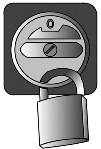
Where the master-switch device used in a given technical system is able to fulfil all the requirements of a safety-disconnection device, it can also take on this function. But that will of course be a reliable expedient only in very simple technical systems. (See figure 3.)
Figure 3. Illustration of elementary principles of a safety disconnection device
Control Gears for Operational Subsystems
Control gears permit movements and functional sequences required for operational subsystems of the technical system to be implemented and controlled safely. Control gears for operational subsystems may be required for set-up (when test runs are to be executed); for regulation (when malfunctions in the operation of the system are to be repaired or when blockages must be cleared); or training purposes (demonstrating operations). In such cases, the normal operation of the system cannot simply be restarted, as the intervening person would be endangered by movements and processes triggered by control signals either erroneously entered or erroneously generated. A control gear for operational subsystems must conform to the following requirements:
- It should permit the safe execution of movements and processes required for operational subsystems of the technical system. For example, certain movements will be executed at reduced speeds, gradually or at lower levels of power (depending on what is appropriate), and processes interrupted immediately, as a rule, if the control panel is no longer attended.
- Its control panels are to be located in areas where their operation does not endanger the operator, and from which the processes controlled are fully visible.
- If several control panels controlling various processes are present at a single location, then these must be clearly marked and arranged in a distinct and understandable manner.
- The control gear for operational subsystems should become effective only when normal operation has been reliably disengaged; that is, it must be guaranteed that no control command can issue effectively from normal operation and over-ride the control gear.
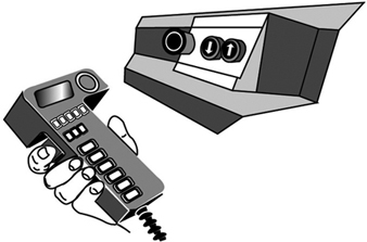
- Unauthorized use of the control gear for operational subsystems should be preventable, for instance, by requiring the use of a special key or code to release the function in question. (See figure 4.)
Figure 4. Actuating devices in the control gears for movable and stationary operational subsystems
The Emergency Switch
Emergency switches are necessary where the normal operation of technical systems could result in hazards which neither appropriate system design nor the taking of appropriate safety precautions are able to prevent. In operational subsystems, the emergency switch is frequently part of the operational subsystem control gear. When operated in case of danger, the emergency switch implements processes which return the technical system to a safe operating state as quickly as possible. With regard to safety priorities, the protection of persons is of primary concern; prevention of damage to material is secondary, unless the latter is liable to endanger persons as well. The emergency switch must fulfil the following requirements:
- It must bring about a safe operating condition of the technical system as quickly as possible.
- Its control panel must be easily recognizable and placed and designed in such a way that it can be operated without difficulty by the endangered persons and can also be reached by others responding to the emergency.
- The emergency processes it triggers must not bring about new hazards; for example, they must not release clamping devices or disconnect magnetic holding fixtures or block safety devices.
- After an emergency switch process has been triggered, the technical system must not be able to be restarted automatically by the resetting of the emergency switch control panel. Rather, the conscious entry of a new function control command must be required. (See figure 5.)
Figure 5. Illustration of the principles of control panels in emergency switches
Function-switch Control Device
Function-switch control devices are used to switch on the technical system for normal operation and to initiate, implement and interrupt the movements and processes designated for normal operation. The function-switch control device is used exclusively in the course of the normal operation of the technical system—that is, during the undisturbed execution of all assigned functions. It is used accordingly by the persons running the technical system. The function-switch control devices must meet the following requirements:
- Their control panels must be accessible and easy to use without danger.
- Their control panels must be clearly and rationally arranged; for example, control knobs should operate “rationally” with regard to controlled movements up and down, right and left. (“Rational” control movements and corresponding effects may be subject to local variation and are sometimes defined by stipulation.)
- Their control panels are to be clearly and intelligibly labelled, with symbols which are easily understood.
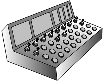
- Processes which require the complete attention of the user for their safe execution must not be able to be triggered either by control signals generated in error or by inadvertent operation of the control devices governing them. Control panel signal processing must be appropriately reliable, and involuntary operation must be prevented by appropriate design of the control device. (See figure 6).
Figure 6. Schematic representation of an operations control panel
Monitoring Switches
Monitoring switches prevent the starting of the technical system as long as the monitored safety conditions are not fulfilled, and they interrupt operation as soon as a safety condition is no longer being fulfilled. They are used, for example, to monitor doors in protective compartments, to check for the correct position of safety guards or to assure that speed or path limits are not exceeded. Monitoring switches must accordingly fulfil the following safety and reliability requirements:
- The switching gear used for monitoring purposes must emit the protective signal in a particularly reliable fashion; for instance, a mechanical monitoring switch might be designed to interrupt the signal flow automatically and with particular reliability.
- The switching tool used for monitoring purposes is to be operated in a particularly reliable fashion when the safety condition is not fulfilled (e.g., when the plunger of a monitoring switch with automatic interruption is forced mechanically and automatically into the interrupt position).
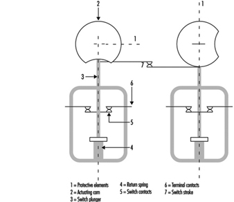
- The monitoring switch must not be able to be improperly turned off, at least not unintentionally and not without some effort; this condition may be fulfilled, for instance, by a mechanical, automatically controlled switch with automatic interruption, when the switch and the operating element are securely mounted. (See figure 7).
Figure 7. Diagram of a switch with a positive mechanical operation and positive disconnection
Safety Control Circuits
Several of the safety switching devices described above do not execute the safety function directly, but rather by emitting a signal which is then transmitted and processed by a safety control circuit and finally reaches those parts of the technical system which exercise the actual safety function. The safety-disconnection device, for example, frequently causes the disconnection of energy at critical points indirectly, whereas a main switch usually directly disconnects the supply of current to the technical system.
Because safety control circuits must transmit safety signals reliably, the following principles must therefore be taken into consideration:
- Safety should be guaranteed even when outside energy is lacking or insufficient, for example, during disconnects or leaks.
- Protective signals function more reliably by interruption of the signal flow; for example, safety switches with opener contact or an open relay contact.
- The protective function of amplifiers, transformers and the like may be achieved more reliably without outside energy; such mechanisms include, for example, electromagnetic switching devices or vents that are closed when at rest.
- Connections effected in error and leaks in the safety-control circuit must not be allowed to lead to false starts or hindrances to stoppage; particularly in the cases of a short circuit between in- and out-conduits, earth leakage, or grounding.
- Outside influences affecting the system in a measure not exceeding the expectations of the user should not interfere with the safety function of the safety-control circuit.
The components used in safety-control circuits must execute the safety function in an especially reliable way. The functions of components which do not meet this requirement are to be implemented by arranging for as diversified a redundancy as possible and are to be kept under surveillance.

