- You are here:
-
Home

-
Part XVI. Construction
-
Construction
- Tools, Equipment and Materials
Processing Ore
Almost all the metals and other inorganic materials that have been exploited occur as the compounds that constitute the minerals that make up the earth’s crust. The forces and processes that have shaped the earth’s surface have concentrated these minerals in widely different amounts. When this concentration is sufficiently great so that the mineral can be economically exploited and recovered, the deposit is referred to as an ore or orebody. However, even then the minerals are not usually available in a form with the purity necessary for immediate processing to the desired end product. In his sixteenth century work on mineral processing Agricola (1950) wrote: “Nature usually creates metals in an impure state, mixed with earth, stones, and solidified juices, it is necessary to separate most of these impurities from the ores as far as can be, before they are smelted.”
Valuable minerals must first be separated from those of no commercial value, which are called gangue. Ore processing refers to this initial treatment of mined material to produce a mineral concentrate of a sufficiently high grade to be satisfactorily processed further to the pure metal or other end product. The differing characteristics of the minerals making up the ore are exploited to separate them from each other by a variety of physical methods that generally leave the chemical composition of the mineral unchanged. (The processing of coal is specifically discussed in the article “Coal preparation”)
Crushing and Grinding
The particle size of the material arriving at the processing plant will depend on the mining operation employed and on the ore type, but it will be relatively large. Comminution, the progressive reduction in the particle size of lumpy ore, is carried out for two reasons: to reduce the material to a more convenient size and to liberate the valuable component from the waste material as a first step towards its effective separation and recovery. In practice, comminution usually consists of the crushing of larger-sized material, followed by the breaking of the material to finer sizes by tumbling it in rotating steel mills.
Crushing
It is not possible to progress from very large lumps to fine material in a single operation or using one machine. Crushing thus is usually a dry operation that typically takes place in stages which are designated as primary, secondary and tertiary.
Primary crushers reduce the ore from anything as large as 1.5 m down to 100 to 200 mm. Machines such as jaw and gyratory crushers apply a fracture force to the large particles, breaking the ore by compression.
In a jaw crusher, ore falls into a wedge-shaped space between a fixed and a moving crushing plate. Material is nipped and squeezed until it breaks and released and nipped again further down as the jaws open and close, until it finally escapes through the gap set at the bottom.
In the gyratory crusher, a long spindle carries a heavy, hard steel conical grinding element that is moved eccentrically by a lower bearing sleeve within the crushing chamber or shell. The relative motion of the crushing faces is produced by the gyration of the eccentrically mounted cone against the outer chamber. Typically this machine is used where a high throughput capacity is required.
Secondary crushing reduces the particle size down to 5 to 20 mm. Cone crushers, rolls and hammer mills are examples of the equipment used. The cone crusher is a modified gyratory crusher with a shorter spindle that is not suspended, but supported in a bearing below the head. A roll crusher consists of two horizontal cylinders rotating towards each other, the rolls drawing the ore into the gap between them and after a single nip discharging the product. The hammer mill is a typical impact crusher mill. Comminution is by the impact of sharp blows applied at high speed by hammers attached to a rotor within the work-space.
Grinding
Grinding, the last stage in comminution, is performed in rotating cylindrical steel vessels known as tumbling mills. Here the mineral particles are reduced to between 10 and 300 μm. A grinding medium, such as steel balls, rods or pebbles (pre-sized lumps of ore much larger than the bulk feed of material), is added to the mill so that the ore is broken down to the desired size. The use of pebbles is termed autogenous grinding. Where the ore type is suitable, run-of-mine (ROM) milling may be used. In this form of autogenous milling the entire ore stream from the mine is fed directly to the mill without pre-crushing, the large lumps of ore acting as the grinding medium.
The mill is generally loaded with crushed ore and grinding medium to just under half full. Studies have shown that the breaking produced by milling is a combination of both impact and abrasion. Mill liners are used to protect the mill shell from wear and, by their design, to reduce slip of the grinding media and improve the lifting and impact portion of milling.
There is an optimal size to which ore must be ground for effective separation and recovery of the valuable component. Undergrinding results in incomplete liberation and poor recovery. Overgrinding increases the difficulty of separation, besides using an excess of expensive energy.
Sizing Separation
After crushing and milling, the products are usually separated simply according to their size. The primary purpose is to produce appropriately sized feed material for further treatment. Oversize material is recycled for further reduction.
Screens
Screening is generally applied to fairly coarse material. It may also be used to produce a reasonably uniform feed size for a subsequent operation where this is required. The grizzly is a series of heavy parallel bars set in a frame that screens out very coarse material. The trommel is an inclined rotating cylindrical screen. By use of a number of sections of different sized screens, several sized products can be simultaneously produced. A variety of other screens and screen combinations may be employed.
Classifiers
Classification is the separation of particles according to their settling rate in a fluid. Differences in density, size and shape are effectively utilized. Classifiers are used to separate coarse and fine material, thereby fractionizing a large size distribution. A typical application is to control a closed-circuit grinding operation. While size separation is the primary objective, some separation by mineral type usually occurs due to density differences.
In a spiral classifier, a rake mechanism lifts the coarser sands from a slurry pool to produce a clean de-slimed product.
The hydrocyclone uses centrifugal force to accelerate settling rates and produce efficient separations of fine-sized particles. A slurry suspension is introduced at high velocity tangentially into a conical shaped vessel. Due to the swirling motion, the faster settling, larger and heavier particles move towards the outer wall, where the velocity is lowest, and settle downwards, while the lighter and smaller particles move towards the zone of low pressure along the axis, where they are carried upward.
Concentration Separation
Concentration separation requires particles to be distinguished as being either those of the valuable mineral or as gangue particles and their effective separation into a concentrate and a tailing product. The objective is to achieve maximum recovery of the valuable mineral at a grade that is acceptable for further processing or sale.
Ore sorting
The oldest and simplest method of concentration is the selection of particles visually and their removal by hand. Hand sorting has its modern equivalents in a number of electronic methods. In photometric methods, particle recognition is based on the difference in reflectivity of different minerals. A blast of compressed air is then activated to remove them from a moving belt of material. The differing conductivity of different minerals may be utilized in a similar manner.
Heavy medium separation
Heavy medium or dense medium separation is a process that depends only on the density difference between minerals. It involves introducing the mixture into a liquid with a density lying between that of the two minerals to be separated, the lighter mineral then floats and the heavier sinks. In some processes it is used for the preconcentration of minerals prior to a final grind and is frequently employed as a cleaning step in coal preparation.
Heavy organic fluids such as tetrabromoethane, which has a relative density of 2.96, are used in certain applications, but on a commercial scale suspensions of finely ground solids that behave as simple Newtonian fluids are generally employed. Examples of the material used are magnetite and ferrosilicon. These form low-viscosity, inert and stable “fluids” and are easily removed from suspension magnetically.
Gravity
Natural separating processes such as river systems have produced placer deposits where heavier larger particles have been separated from lighter smaller ones. Gravity techniques mimic these natural processes. Separation is brought about by the movement of the particle in response to the force of gravity and the resistance exerted by the fluid in which separation takes place.
Over the years, many types of gravity separators have been developed, and their continued use testifies to the cost-effectiveness of this type of separation.
In a jig a bed of mineral particles is brought into suspension (“fluidized”) by a pulsating current of water. As the water drains back between each cycle, the denser particles fall below the less dense and during a period of draining small particles, and particularly smaller denser particles, penetrate between the spaces between the larger particles and settle lower in the bed. As the cycle is repeated, the degree of separation increases.
Shaking tables treat finer material than jigs. The table consists of a flat surface that is inclined slightly from front to back and from one end to the other. Wooden riffles divide the table longitudinally at right angles. Feed enters along the top edge, and the particles are carried downwards by the flow of water. At the same time they are subject to asymmetrical vibrations along the longitudinal or horizontal axis. Denser particles which tend to be trapped behind the riffle are shuffled across the table by the vibrations.
Magnetic separation
All materials are influenced by magnetic fields, although for most the effect is too slight to be detected. However, if one of the mineral components of a mixture has a reasonably strong magnetic susceptibility, this can be used to separate it from the others. Magnetic separators are classified into low- and high-intensity machines, and further into dry- and wet-feed separators.
A drum-type separator consists of a rotating non-magnetic drum containing within its shell stationary magnets of alternating polarity. Magnetic particles are attracted by the magnets, pinned to the drum and conveyed out of the magnetic field. A wet high- intensity separator (WHIMS) of the carousel type consists of a concentric rotating matrix of iron balls that passes through a strong electromagnet. Slurried residues are poured into the matrix where the electromagnet operates, and magnetic particles are attracted to the magnetized matrix while the bulk of the slurry passes through and exits via a base grid. Just past the electromagnet, the field is reversed and a stream of water is used to remove the magnetic fraction.
Electrostatic separation
Electrostatic separation, once commonly used, was displaced to a considerable extent by the advent of flotation. However, it is successfully applied to a small number of minerals, such as rutile, for which other methods prove difficult and where the conductivity of the mineral makes electrostatic separation possible.
The method exploits differences in the electrical conductivity of the different minerals. Dry feed is carried into the field of an ionizing electrode where the particles are charged by ion bombardment. Conducting particles rapidly lose this charge to a grounded rotor and are thrown from the rotor by centrifugal force. Non-conductors lose their charge more slowly, remain clinging to the earth conductor by electrostatic forces, and are carried around to a collection point.
Flotation
Flotation is a process of separation that exploits differences in the physico-chemical surface properties of different minerals.
Chemical reagents called collectors are added to the pulp and react selectively with the surface of the valuable mineral particles. The reaction products formed makes the surface of the mineral hydrophobic or non-wettable, so that it readily attaches to an air bubble.
In each cell of a flotation circuit the pulp is agitated and introduced air is dispersed into the system. The hydrophobic mineral particles attach to the air bubbles and, with a suitable frothing agent present, these form a stable froth at the surface. This continuously overflows the sides of the flotation cell, carrying its mineral load with it.
A flotation plant consist of banks of interconnected cells. A first concentrate produced in rougher bank is cleaned of unwanted gangue components in a cleaner bank, and if necessary recleaned in a third bank of cells. Additional valuable mineral may be scavenged in a fourth bank and recycled to the cleaner banks before the tails are finally discarded.
Dewatering
Following most operations it is necessary to separate the water used in the separation processes from the concentrate produced or from the waste gangue material. In dry environments this is particularly important so that the water may be recycled for re-use.
A settling tank consists of a cylindrical vessel into which pulp is fed at the centre via a feed-well. This is placed below the surface to minimize disturbance of the settled solids. Clarified liquid overflows the sides of the tank into a launder. Radial arms with blades rake the settled solids towards the centre, where they are withdrawn. Flocculants may be added to the suspension to accelerate the settling rate of the solids.
Filtration is the removal of solid particles from the fluid to produce a cake of concentrate that can then be dried and transported. A common form is the continuous vacuum filter, typical of which is the drum filter. A horizontal cylindrical drum rotates in an open tank with the lower section immersed in pulp. The shell of the drum consists of a series of compartments covered by a filter medium. The inner double-walled shell is connected to a valve mechanism on the central shaft that permits either vacuum or pressure to be applied. Vacuum is applied to the section immersed in the pulp, drawing water through the filter and forming a cake of concentrate on the cloth. The vacuum dewaters the cake once out of the slurry. Just before the section re-enters the slurry, pressure is applied to blow off the cake. Disc filters operate on the same principle, but consist of a series of discs attached to the central shaft.
Tailings Disposal
Only a small fraction of the mined ore consists of valuable mineral. The remainder is gangue that after processing forms the tailings that must be disposed of.
The two major considerations in tailings disposal are safety and economics. There are two aspects to safety: the physical considerations surrounding the dump or dam in which the tailings are placed; and pollution by the waste material that may affect human health and cause damage to the environment. Tailings must be disposed of in the most cost-effective manner possible commensurate with safety.
Most commonly the tailings are sized, and the coarse sand fraction is used to construct a dam at a selected site. The fine fraction or slime is then pumped into a pond behind the dam wall.
Where toxic chemicals such as cyanide are present in the waste waters, special preparation of the base of the dam (e.g., by the use of plastic sheeting) may be necessary to prevent the possible contamination of ground waters.
As far as possible, the water recovered from the dam is recycled for further use. This may be of great importance in dry regions and is increasingly becoming required by legislation aimed at preventing the pollution of ground and surface water by chemical pollutants.
Heap and in Situ Leaching
Much of the concentrate produced by ore processing is processed further by hydrometallurical methods. The metal values are leached or dissolved from the ore, and different metals are separated from each other. The solutions obtained are concentrated, and the metal then recovered by steps such as precipitation and electrolytic or chemical deposition.
Many ores are of too low a grade to justify the cost of pre-concentration. Waste material may also still contain a certain amount of metal value. In some instances, such material may be economically processed by a version of a hydrometallurgical process known as heap or dump leaching.
Heap leaching was established at Rio Tinto in Spain more than 300 years ago. Water percolating slowly through heaps of low-grade ore was coloured blue by dissolved copper salts arising from oxidation of the ore. The copper was recovered from solution by precipitation onto scrap iron.
This basic process is utilized for oxide and sulphide heap leaching of low grade and waste material around the world. Once a heap or dump of the material has been created, a suitable solubilizing agent (e.g., an acid solution) is applied by sprinkling or flooding the top of the heap and the solution that seeps to the bottom is recovered.
While heap leaching has long been successfully practised, it was only relatively recently that the important role of certain bacteria in the process was recognized. These bacteria have been identified as the iron-oxidizing species Thiobacillus ferrooxidans and the sulphur-oxidizing species Thiobacillus thiooxidans. The iron-oxidizing bacteria derive energy from the oxidation of ferrous ions to ferric ions and the sulphur-oxidizing species by the oxidation of sulphide to sulphate. These reactions effectively catalyze the accelerated oxidation of the metal sulphides to the soluble metal sulphates.
In situ leaching, sometimes called solution mining, is effectively a variation of heap leaching. It consists of the pumping of solution into abandoned mines, caved in workings, remote worked-out areas or even entire ore bodies where these are shown to be permeable to solution. The rock formations must lend themselves to contact with the leaching solution and to the necessary availability of oxygen.
Surface Coal Mining Managment
The geological characteristics of surface coal mining which distinguish it from other surface mining are the nature of formation and its relatively low value, which often require surface coal mines to move large volumes of overburden over a large area (i.e., it has a high stripping ratio). As a result, surface coal mines have developed specialized equipment and mining techniques. Examples include a dragline strip mine which mines in strips of 30 to 60 m wide, sidecasting material in pits up to 50 km long. Rehabilitation is an integral part of the mining cycle due to the significant disturbance of the involved areas.
Surface coal mines vary from being small (i.e., producing less than 1 million tonnes per annum) to large (above 10 million tonnes per annum). The workforce required depends on the size and type of the mine, the size and amount of equipment and the amount of coal and overburden. There are some typical measurements which indicate the productivity and size of the workforce. These are:
1. Output per miner expressed as tonnes per miner per year; this would range from 5,000 tonnes per miner per year to 40,000 tonnes per miner per year.
2. Total material moved expressed in tonnes per miner per year. This productivity indicator combines the coal and the overburden; productivity of 100,000 tonnes per miner per year would be low with 400,000 tonnes per miner per year being the very productive end of the scale.
Due to the large capital investment involved, many coal mines operate on a seven day continuous shift roster. This involves four crews: three work three shifts of eight hours each with the fourth crew covering rostered time off.
Mine Planning
Mine planning for surface coal mines is a repetitive process which can be summarized in a checklist. The cycle begins with geology and marketing and finishes with an economic evaluation. The level of detail (and cost) of the planning increases as the project goes through different stages of approval and development. Feasibility studies cover the work prior to development. The same checklist is used after production commences to develop annual and five-year plans as well as plans for closing down the mine and rehabilitating the area when all the coal has been extracted.
Significantly, the need for planning is ongoing and the plans need frequent updating to reflect changes in the market, technology, legislation and knowledge of the deposit learned as the mining progresses.
Geological Influences
Geological features have a major influence in the selection of the mining method and equipment used in a particular surface coal mine.
Seam attitude, commonly known as dip, represents the angle between the seam being mined and the horizontal plane. The steeper the dip the more difficult it is to mine. The dip also affects the stability of the mine; the limiting dip for dragline operations is around 7°.
The strength of coal and waste rock determines what equipment can be used and whether or not the material has to be blasted. Continuous mining equipment, such as bucketwheel excavators commonly used in eastern Europe and Germany, is limited to material of very low strength that does not require blasting. Typically, however, the overburden is too hard to be dug without some blasting to fragment the rock into smaller sized pieces which can then be excavated by shovels and mechanical equipment.
As the depth of coal seams increase, the cost of transporting the waste and coal to the surface or to the dump becomes higher. At some point, it would become more economical to mine by underground methods than by open-cut methods.
Seams as thin as 50 mm can be mined but the recovery of coal becomes more difficult and expensive as seam thickness decreases.
Hydrology refers to the amount of water in the coal and overburden. Significant quantities of water affect stability and the pumping requirements add to the cost.
The magnitude of the coal reserves and the scale of operation influences what equipment can be used. Small mines require smaller and relatively more expensive equipment, whereas large mines enjoy the economies of scale and lower costs per unit of production.
Environmental characteristics refers to the behaviour of the overburden after it has been mined. Some overburden is termed “acid producing” which means that when exposed to air and water it will produce acid which is detrimental to the environment and requires special treatment.
The combination of the above factors plus others determines which mining method and equipment is appropriate for a particular surface coal mine.
The Mining Cycle
Surface coal mining methodology can be broken into a series of steps.
Removing topsoil and either storing it or replacing it on areas being rehabilitated is an important part of the cycle as the objective is to return the land use to at least as good a condition as it was before mining began. Topsoil is an important component as it contains plant nutrients.
Ground preparation may involve using explosives to fragment the large rocks. In some instances, this is done by bulldozers with rippers which use mechanical force to break the rock into smaller pieces. Some mines where the strength of the rock is low require no ground preparation as the excavator can dig directly from the bank.
Waste removal is the process of mining the rock overlying the coal seam and transporting it to the dump. In a strip mine where the dump is in an adjacent strip, it is a sidecast operation. In some mines, however, the dump may be several kilometres away due to the structure of the seam and available dump space and transport to the dump by trucks or conveyors is necessary.
Coal mining is the process of removing the coal from the exposed face in the mine and transporting it out of the pit. What happens next depends on the location of the coal market and its end use. If fed to an onsite power station, it is pulverised and goes directly to the boiler. If the coal is low grade it may be upgraded by “washing” the coal in a preparation plant. This separates the coal and overburden to yield a higher grade product. Before it is sent to market, this coal usually needs some crushing to get it to a uniform size, and blending to control variations in quality. It may be transported by road, conveyor, train, barge or ship.
Rehabilitation involves shaping the dump to restore the terrain and meet drainage criteria, replacing topsoil and planting vegetation to return it to its original state. Other environmental management considerations include:
- water management: diversion of existing water courses and control of mine water by sediment dams and recycling so that contaminated water is not discharged
- visual planning : ensuring that the visual impact is minimized
- flora and fauna: to restoring trees and vegetation and replace indigenous wild life
- archaeology: preservation and/or restoration of culturally significant sites
- final void: what to do with the hole after mining has stopped (e.g., it may be filled in or turned into a lake)
- air blast and vibration, due to blasting, which need to be managed by specific techniques if buildings are nearby
- noise and dust, which need to be managed to avoid creating a nuisance for nearby dwellings and communities.
The impact of surface coal mining on the overall environment can be significant but with appropriate planning and control throughout all phases of the enterprise, it can be managed to meet all requirements.
Mining Methods and Equipment
Three main mining methods are used for surface coal mining: truck and shovel; draglines; and conveyor-based systems, such as bucketwheel excavators and in-pit crushers. Many mines use combinations of these, and there are also specializd techniques such as auger mining and continuous highwall miners. These constitute only a small proportion of total surface coal mining production. The dragline and bucketwheel systems were developed specifically for surface coal mining whereas truck and shovel mining systems are used throughout the mining industry.
The truck and shovel mining method involves an excavator, such as an electric rope shovel, a hydraulic excavator or a front-end loader, to load overburden into trucks. The size of the trucks can vary from 35 tonnes up to 220 tonnes. The truck transports the overburden from the mining face to the dumping area where a bulldozer will push and pile the rock to shape the dump for rehabilitation. The truck and shovel method is noted for its flexibility; examples are found in most countries of the world.
Draglines are one of the cheapest methods to mine the overburden, but are limited in their operation by the length of the boom,which is generally 100 m long. The dragline swings on its centre point and can therefore dump the material approximately 100 m from where it is sitting. This geometry requires that the mine be laid out in long narrow strips.
The main limitation of the dragline is that it can only dig to a depth of approximately 60 m; beyond this, another form of supplementary overburden removal such as the truck and shovel fleet is required.
Conveyor-based mining systems use conveyors to transport the overburden instead of trucks. Where the overburden is low strength it can be mined directly from the face by a bucketwheel excavator. It is often called a “continuous” mining method because it feeds the overburden and coal without interruption. Draglines and shovels are cyclical with each bucket load taking 30 to 60 seconds. Harder overburden requires a combination of blasting or an in-pit crusher and shovel loading to feed it onto the conveyor. Conveyor-based surface coal mining systems are most suitable where the overburden has to be transported significant distances or up significant heights.
Conclusion
Surface coal mining involves specialized equipment and mining techniques which allow the removal of large volumes of waste and coal from large areas. Rehabilitation is an integral and important part of the process.
Surface Mining Methods
Mine Development
Pit planning and layout
The overall economic goal in surface mining is to remove the least amount of material while gaining the greatest return on investment by processing the most marketable mineral product. The higher the grade of the mineral deposit, the greater the value. To minimize capital investment while accessing the highest valued material within a mineral deposit, a mine plan is developed that precisely details the manner in which the ore body will be extracted and processed. As many ore deposits are not a uniform shape, the mine plan is preceded by extensive exploratory drilling to profile the geology and position of the ore body. The size of the mineral deposit dictates the size and layout of the mine. The layout of a surface mine is dictated by the mineralogy and geology of the area. The shape of most open-pit mines approximates a cone but always reflects the shape of the mineral deposit being developed. Open-pit mines are constructed of a series of concentric ledges or benches that are bisected by mine access and haulage roads angling down from the rim of the pit to the bottom in a spiral or zigzag orientation. Regardless of size, the mine plan includes provisions for pit development, infrastructure, (e.g., storage, offices and maintenance) transportation, equipment, mining ratios and rates. Mining rates and ratios influence the life of the mine which is defined by depletion of the ore body or realization of an economic limit.
Contemporary open-pit mines vary in scale from small privately-operated enterprises processing a few hundred tonnes of ore per day to expanded industrial complexes operated by governments and multinational corporations that mine more than one million tonnes of material per day. The largest operations can involve many square kilometres in area.
Stripping overburden
Overburden is waste rock consisting of consolidated and unconsolidated material that must be removed to expose the underlying ore body. It is desirable to remove as little overburden as possible in order to access the ore of interest, but a larger volume of waste rock is excavated when the mineral deposit is deep. Most removal techniques are cyclical with interruption in the extraction (drilling, blasting and loading) and removal (haulage) phases. This is particularly true for hard rock overburden which must be drilled and blasted first. An exception to this cyclical effect are dredges used in hydraulic surface mining and some types of loose material mining with bucket wheel excavators. The fraction of waste rock to ore excavated is defined as the stripping ratio. Stripping ratios of 2:1 up to 4:1 are not uncommon in large mining operations. Ratios above 6:1 tend to be less economically viable, depending on the commodity. Once removed, overburden can be used for road and tailings construction or may have non-mining commercial value as fill dirt.
Mining equipment selection
The selection of mining equipment is a function of the mine plan. Some of the factors considered in the selection of mine equipment include the topography of the pit and surrounding area, the amount of ore to be mined, the speed and distance the ore must be transported for processing and the estimated mine life, among others. In general, most contemporary surface mining operations rely on mobile drill rigs, hydraulic shovels, front-end loaders, scrapers and haul trucks to extract ore and initiate ore processing. The larger the mine operation, the larger the capacity of equipment required to maintain the mine plan.
Equipment is generally the largest available to match the economy of scale of surface mines with consideration for matching the capacities of equipment. For example, a small front-end loader can fill a large haul truck but the match is not efficient. Similarly, a large shovel can load smaller trucks but requires the trucks to decrease their cycle times and does not optimize utilization of the shovel since one shovel bucket may contain enough ore for more than one truck. Safety may be compromised by attempting to load only half of a bucket or if a truck is overloaded. Also, the scale of equipment selected must match the available maintenance facilities. Large equipment is often maintained where it malfunctions due to the logistical difficulties associated with transporting it to established maintenance facilities. When possible, the mine’s maintenance facilities are designed to accommodate the scale and quantity of the mine equipment. Therefore, as new larger equipment is introduced into the mine plan, the supporting infrastructure, including the size and quality of haul roads, tools and maintenance facilities, must also be addressed.
Conventional Methods of Surface Mining
Open-pit mining and strip mining are the two major categories of surface mining which account for more than 90% worldwide surface mining production. The primary differences between these mining methods are the location of the ore body and the mode of mechanical extraction. For loose rock mining, the process is essentially continuous with extraction and haulage steps running in series. Solid rock mining requires a discontinuous process of drilling and blasting prior to the loading and hauling stages. Strip mining (or open-cast mining) techniques relate to the extraction of ore bodies that are near the surface and relatively flat or tabular in nature and mineral seams. It uses a variety of different types of equipment including shovels, trucks, drag lines, bucket wheel excavators and scrapers. Most strip mines process non-hard rock deposits. Coal is the most common commodity that is strip mined from surface seams. In contrast, open-pit mining is employed to remove hard rock ore that is disseminated and/or located in deep seams and is typically limited to extraction by shovel and truck equipment. Many metals are mined by the open-pit technique: gold, silver and copper, to name a few.
Quarrying is a term used to describe a specialized open-pit mining technique wherein solid rock with a high degree of consolidation and density is extracted from localized deposits. Quarried materials are either crushed and broken to produce aggregate or building stone, such as dolomite and limestone, or combined with other chemicals to produce cement and lime. Construction materials are produced from quarries located in close proximity to the site of material use to reduce transportation costs. Dimension stone such as flagstone, granite, limestone, marble, sandstone and slate represent a second class of quarried materials. Dimension stone quarries are found in areas having the desired mineral characteristics which may or may not be geographically remote and require transportation to user markets.
Many ore bodies are too diffuse and irregular, or too small or deep to be mined by strip or open-pit methods and must be extracted by the more surgical approach of underground mining. To determine when open-pit mining is applicable, a number of factors must be considered, including the terrain and elevation of the site and region, its remoteness, climate, infrastructure such as roads, power and water supply, regulatory and environmental requirements, slope stability, overburden disposal and product transportation, among others.
Terrain and elevation: Topography and elevation also play an important role in defining the feasibility and scope of a mining project. In general, the higher the elevation and rougher the terrain, the more difficult mine development and production are likely to be. A higher grade of mineral in an inaccessible mountainous location may be mined less efficiently than a lower grade of ore in a flat location. Mines located at lower elevations generally experience less inclement weather-related problems for exploration, development and production of mines. As such, topography and location affect the mining method as well as economic feasibility.
The decision to develop a mine occurs after exploration has characterized the ore deposit and feasibility studies have defined the options for mineral extraction and processing. Information that is necessary to establish a development plan may include the shape, size and grade of minerals in the ore body, the total volume or tonnage of material including overburden and other factors, such as hydrology and access to a source of process water, availability and source of power, waste rock storage sites, transportation requirements and infrastructure features, including the location of population centres to support the labour force or the need to develop a townsite.
Transportation requirements may include roads, highways, pipelines, airports, railroads, waterways and harbours. For surface mines, large land areas are generally required that may have no existing infrastructure. In such instances roads, utilities and living arrangements must be established first. The pit would be developed in connection with other processing elements such as waste rock storage areas, crushers, concentrators, smelters and refineries, depending on the degree of integration required. Due to the large amount of capital necessary to finance these operations, development may be conducted in phases to take advantage of the earliest possible saleable or leasable mineral to help finance the remainder of the development.
Production and Equipment
Drilling and blasting
Mechanical drilling and blasting are the first steps in extracting ore from most developed open-pit mines and are the most common method used to remove hard rock overburden. While there are many mechanical devices capable of loosening hard rock, explosives are the preferred method as no mechanical device can currently match the fracturing capability of energy contained in explosive charges. A commonly used hard rock explosive is ammonium nitrate. Drilling equipment is selected on the basis of the nature of the ore and the speed and depth of the holes necessary to fracture a specified tonnage of ore per day. For example, in mining a 15-m bench of ore, 60 or more holes will generally be drilled 15 m back from the current muck face depending on the length of the bench to be mined. This must occur with enough lead-time to allow for site preparation for subsequent loading and haulage activities.
Loading
Surface mining is now typically conducted utilizing table shovels, front-end loaders or hydraulic shovels. In open-pit mining loading equipment is matched with haul trucks that can be loaded in three to five cycles or passes of the shovel; however, various factors determine the preference of loading equipment. With sharp rock and/or hard digging and/or wet climates, tracked shovels are preferable. Conversely, rubber-tyred loaders have much lower capital cost and are preferred for loading material that is low volume and easy to dig. Additionally, loaders are very mobile and well-suited for mining scenarios requiring rapid movements from one area to another or for ore blending requirements. Loaders are also frequently used to load, haul and dump material into crushers from blending stock piles deposited near crushers by haul trucks.
Hydraulic shovels and cable shovels have similar advantages and limitations. Hydraulic shovels are not preferred for digging hard rock and cable shovels are generally available in larger sizes. Therefore, large cable shovels with payloads of about 50 cubic metres and greater are the preferred equipment at mines were production exceeds 200,000 tonnes per day. Hydraulic shovels are more versatile on the mine face and allow greater operator control to selectively load the from either the bottom or top half of the mine face. This advantage is helpful where separation of waste from ore can be achieved at the loading zone thereby maximizing the ore grade that is hauled and processed.
Hauling
Haulage in open-pit and strip mines is most commonly accomplished by haul trucks. The role of haul trucks in many surface mines is restricted to cycling between the loading zone and the transfer point such as an in-pit crushing station or conveyance system. Haul trucks are favoured based on their flexibility of operation relative to railroads, which were the preferred haulage method until the 1960s. However, the cost of transporting materials in surface metal and non-metal pits is generally greater than 50% of the total operating cost of the mine. In-pit crushing and conveying through belt conveyor systems has been a primary factor in reducing haulage costs. Technical developments in haul trucks such as diesel engines and electrical drives have lead to much larger capacity vehicles. Several manufactures currently produce 240 tonne capacity trucks with expectation for greater than 310 tonne capacity trucks in the near future. In addition, the use of computerized dispatch systems and global satellite positioning technology allow vehicles to be tracked and scheduled with improved efficiency and productivity.
Haul road systems may use single or dual direction traffic. Traffic may be either left or right lane configuration. Left lane traffic is frequently preferred to improve operator visibility of tyre position on very large trucks. Safety is also improved with left hand traffic by reducing the potential for driver-side collision in the centre of a road. Haul road gradients are typically limited to between 8 and 15% for sustained hauls and optimally are about 7 to 8%. Safety and water drainage requires long gradients to include at least 45-m sections with a maximum gradient of 2% for every 460 m of severe gradient. Road berms (elevated dirt borders) located between roads and adjacent excavations are standard safety features in surface mines. They may also be placed in the middle of the road to separate opposing traffic. Where switch-back haul roads exist, increasing elevation escape lanes may be installed at the end of long steep grades. Road edge barriers such as berms are standard and should be located between all roads and adjacent excavations. High-quality roads enhance maximum productivity by maximizing safe truck speeds, reduced down-time for maintenance and reduced driver fatigue. Haul-truck road maintenance contributes to reduced operating costs through reduced fuel consumption, longer tyre life and reduced repair costs.
Rail haulage, under the best of conditions, is superior to other methods of haulage for transport of ore over long distances outside the mine. However, as a practical matter, rail haulage is no longer widely used in open-pit mining since the advent of electrical and diesel-powered trucks. Rail haulage was replaced to capitalize on the greater versatility and flexibility of haul trucks and in-pit conveyor systems. Railroads requires very gentle grades of 0.5 to a maximum of 3% for up-hill hauls. Capital investment for railroad engines and track requirements is very high and requires a long mine life and large production outputs to justify return on investment.
Ore handling (conveyance)
In-pit crushing and conveying is a methodology that has grown in popularity since first being implemented in the mid-1950s. Location of a semi-mobile crusher in the mine pit with the subsequent transport out of the pit by a conveyor system has resulted in significant production advantages and cost savings over traditional vehicle haulage. High cost haulage road construction and maintenance is reduced and labour costs associated with haul truck operation and truck maintenance and fuel are minimized.
The purpose of the in-pit crusher system is primarily to allow transport of ore by conveyor. In-pit crusher systems may range from permanent facilities to fully mobile units. However, more commonly, crushers are constructed in a modular form to allow some portability within the mine. Crushers might be relocated every one to ten years; it may require hours, days or months to complete the move depending on the size and complexity of the unit and the relocation distance.
Conveyors’ advantages over haul trucks include instantaneous start up, automatic and continuous operation, and a high degree of reliability with up 90 to 95% availability. They are generally not impaired by inclement weather. Conveyors also have much lower labour requirements relative to haul trucks; operating and maintaining a truck fleet may require ten times as many crew members as an equivalent-capacity conveyor system. Also, conveyors can operate at grades up to 30% while maximum grades for trucks are generally 10%. Using steeper grades lowers the need to remove low-grade overburden material and may reduce the need to establish high cost haulage roads. Conveyors systems are also integrated into bucket wheel shovels in many surface coal operations, which eliminates the need for haulage trucks.
Solution Mining Methods
Solution mining, the most common of two types of aqueous mining, is employed to extract soluble ore where conventional mining methods are less efficient and/or less economical. Also known as leaching or surface leaching, this technique can be a primary mining method, as with gold and silver leach mining, or it can supplement the conventional pyrometallurgical steps of smelting and refining, as in the case of leaching low-grade copper oxide ores.
Environmental aspects of surface mining
The significant environmental effects of surface mines attract attention wherever the mines are located. Alteration of terrain, destruction of plant life and adverse effects on indigenous animals are inevitable consequences of surface mining. Contamination of surface and underground waters often presents problems, particularly with the use of lixiviants in solution mining and the run-off from hydraulic mining.
Thanks to the increased attention from environmentalists around the world and the use of planes and aerial photography, mining enterprises are no longer free to “dig and run” when the extraction of the desired ore has been complete. Laws and regulations have been promulgated in most of the developed countries and, through the activities of international organizations, are being urged where they do not yet exist. They establish an environmental management programme as an integral element in every mining project and stipulate such requirements as preliminary environmental impact assessments; progressive rehabilitation programmes, including restoration of land contours, reforestration, replanting of indigenous fauna, restocking of indigenous wild life and so on; as well as concurrent and long-term compliance auditing (UNEP 1991,UN 1992, Environmental Protection Agency (Australia) 1996, ICME 1996). It is essential that these be more than statements in the documentation required for the necessary government licenses. The basic principles must be accepted and practised by managers in the field and communicated to workers on all levels.
Regardless of the necessity or economic advantage, all surface solution methods share two common characteristics: (1) ore is mined in the usual way and then stockpiled; and, (2) an aqueous solution is applied to the top of the ore stock which reacts chemically with the metal of interest from which the resulting metal salt solution is channelled through the stock pile for collection and processing. The application of surface solution mining is dependent on the volume, the metallurgy of the mineral(s) of interest and the related host rock, and available area and drainage to develop sufficiently large leach dumps to make the operation economically viable.
The development of leach dumps in a surface mine in which solution mining is the primary production method is the same as all open-pit operations with the exception that the ore is destined solely for the dump and not a mill. In mines with both milling and solution methods, ore is segregated into milled and leached portions. For example, most copper sulphide ore is milled and purified to market grade copper by smelting and refining. Copper oxide ore, which is not generally amenable to pyrometallurgical processing, is routed to leach operations. Once the dump is developed, the solution leaches the soluble metal from the surrounding rock at a predictable rate that is controlled by the design parameters of the dump, the nature and volume of the solution applied, and the concentration and mineralogy of the metal in the ore. The solution used to extract the soluble metal is referred to as a lixiviant. The most common lixiviants used in this mining sector are dilute solutions of alkaline sodium cyanide for gold, acidic sulphuric acid for copper, aqueous sulphur dioxide for manganese and sulphuric acid-ferric sulphate for uranium ores; however, most leached uranium and soluble salts are collected by in-situ mining in which the lixiviant is injected directly into the ore body without prior mechanical extraction. This latter technique enables low-grade ores to be processed without extracting the ore from the mineral deposit.
Health and safety aspects
The occupational health and safety hazards associated with mechanical extraction of the ore in solution mining are essentially similar to those of conventional surface mine operations. An exception to this generalization is the need for non-leaching ore to undergo primary crushing in the surface mine pit before being conveyed to a mill for conventional processing, whereas ore is generally transported by haul truck directly from the extraction site to the leach dump in solution mining. Solution mining workers would therefore have less exposure to primary crushing hazards such as dust, noise and physical hazards.
The leading causes of injuries in surface mine environments include materials handling, slips and falls, machinery, hand-tool use, power haulage and electrical source contact. However, unique to solution mining is the potential exposure to the chemical lixiviants during transportation, leach field activities and chemical and electrolytic processing. Acid mist exposures may occur in metal electrowinning tankhouses. Ionizing radiation hazards, which increase proportionally from extraction to concentration, must be addressed in uranium mining.
Hydraulic Mining Methods
In hydraulic mining, or “hydraulicking”, high pressure water spray is used to excavate loosely consolidated or unconsolidated material into a slurry for processing. Hydraulic methods are applied primarily to metal and aggregate stone deposits, although coal, sandstone and metal mill tailings are also amenable to this method. The most common and best known application is placer mining in which concentrations of metals such as gold, titanium, silver, tin and tungsten are washed from within an alluvial deposit (placer). Water supply and pressure, ground slope gradient for runoff, distance from the mine face to the processing facilities, degree of consolidation of the mineable material and the availability of waste disposal areas are all primary considerations in the development of a hydraulic mining operation. As with other surface mining, the applicability is location specific. Inherent advantages of this method mining include relatively low operating costs and flexibility resulting from the use of simple, rugged and mobile equipment. As a result, many hydraulic operations develop in remote mining areas where infrastructure requirements are not a limitation.
Unlike other types of surface mining, hydraulic techniques rely on water as the medium for both mining and conveyance of the mined material (“sluicing”). High pressure water sprays are delivered by monitors or water cannons to a placer bank or mineral deposit. They disintegrate gravel and unconsolidated material, which washes into collection and processing facilities. Water pressures may vary from a normal gravity flow for very loose fine materials to thousands of kilograms per square centimetre for unconsolidated deposits. Bulldozers and graders or other mobile excavating equipment are sometimes employed to facilitate mining of more compacted materials. Historically, and in modem small-scale operations, the collection of the slurry or runoff is managed with small volume sluice boxes and catches. Commercial-scale operations rely on pumps, containment and settling basins and separation equipment that can process very large volumes of slurry per hour. Depending on the size of the deposit to be mined, the operation of the water monitors may be manual, remotely controlled or computer controlled.
When hydraulic mining occurs underwater it is referred to as dredging. In this method a floating processing station extracts loose deposits such as clay, silt, sand, gravel and any associated minerals using a bucket line, drag line and/or submerged water jets. The mined material is transported hydraulically or mechanically to a washing station which may be part of the dredging rig or physically separate with subsequent processing steps to segregate and complete processing. While dredging is used to extract commercial minerals and aggregate stone, it is best known as a technique used to clear and deepen water channels and floodplains.
Health and safety
Physical hazards in hydraulic mining differ from those in surface mining methods. Due to the minimal application of drilling, explosives, haulage and reduction activities, safety hazards tend to be associated mostly often with high pressure water systems, manual movement of mobile equipment, proximity issues involving power supplies and water, proximity issues associated with collapse of the mine face and maintenance activities. Health hazards primarily involve exposure to noise and dusts and ergonomic hazards related to equipment handling. Dust exposure is generally less of an issue than in traditional surface mining due to the use of water as the mining medium. Maintenance activities such as uncontrolled welding may also contribute to worker exposures.
Underground Coal Mining
Underground coal production first began with access tunnels, or adits, being mined into seams from their surface outcrops. However, problems caused by inadequate means of transport to bring coal to the surface and by the increasing risk of igniting pockets of methane from candles and other open flame lights limited the depth to which early underground mines could be worked.
Increasing demand for coal during the Industrial Revolution gave the incentive for shaft sinking to access deeper coal reserves, and by the mid-twentieth century by far the greater proportion of world coal production came from underground operations. During the 1970s and 1980s there was widespread development of new surface coal mine capacity, particularly in countries such as the United States, South Africa, Australia and India. In the 1990s, however, renewed interest in underground mining resulted in new mines being developed (in Queensland, Australia, for instance) from the deepest points of former surface mines. In the mid-1990s, underground mining accounted for perhaps 45% of all the hard coal mined worldwide. The actual proportion varied widely, ranging from under 30% in Australia and India to around 95% in China. For economic reasons, lignite and brown coal are rarely mined underground.
An underground coal mine consists essentially of three components: a production area; coal transport to the foot of a shaft or decline; and either hoisting or conveying the coal to the surface. Production also includes the preparatory work that is needed in order to permit access to future production areas of a mine and, in consequence, represents the highest level of personal risk.
Mine Development
The simplest means of accessing a coal seam is to follow it in from its surface outcrop, a still widely practised technique in areas where the overlying topography is steep and the seams are relatively flat-lying. An example is the Appalachian coalfield of southern West Virginia in the United States. The actual mining method used in the seam is immaterial at this point; the important factor is that access can be gained cheaply and with minimal construction effort. Adits are also commonly used in areas of low-technology coal mining, where the coal produced during mining of the adit can be used to offset its development costs.
Other means of access include declines (or ramps) and vertical shafts. The choice usually depends on the depth of the coal seam being worked: the deeper the seam, the more expensive it is to develop a graded ramp along which vehicles or belt conveyors can operate.
Shaft sinking, in which a shaft is mined vertically downwards from the surface, is both costly and time-consuming and requires a longer lead-time between the commencement of construction and the first coal being mined. In cases where the seams are deep-lying, as in most European countries and in China, shafts often have to be sunk through water-bearing rocks overlying the coal seams. In this instance, specialist techniques, such as ground freezing or grouting, have to be used to prevent water from flowing into the shaft, which is then lined with steel rings or cast concrete to provide a long-term seal.
Declines are typically used to access seams that are too deep for open-cast mining, but which are still relatively near-surface. In the Mpumalanga (eastern Transvaal) coalfield in South Africa, for instance, the mineable seams lie at a depth of no more than 150 m; in some areas, they are mined from opencasts, and in others underground mining is necessary, in which case declines are often used to provide access for mining equipment and to install the belt conveyors used to carry the cut coal out of the mine.
Declines differ from adits in that they are usually excavated in rock, not coal (unless the seam dips at a constant rate), and are mined to a constant gradient to optimize vehicle and conveyor access. An innovation since the 1970s has been the use of belt conveyors running in declines to carry deep-mine production, a system that has advantages over traditional shaft hoisting in terms of capacity and reliability.
Mining Methods
Underground coal mining encompasses two principal methods, of which many variations have evolved to address mining conditions in individual operations. Room-and-pillar extraction involves mining tunnels (or roadways) on a regular grid, often leaving substantial pillars for long-term support of the roof. Longwall mining achieves total extraction of large parts of a coal seam, causing the roof rocks to collapse into the mined-out area.
Room-and-pillar mining
Room-and-pillar mining is the oldest underground coal mining system, and the first to use the concept of regular roof support to protect mine workers. The name room-and-pillar mining derives from the pillars of coal that are left behind on a regular grid to provide in situ support to the roof. It has been developed into a high-production, mechanized method that, in some countries, accounts for a substantial proportion of the total underground output. For instance, 60% of underground coal production in the United States comes from room-and-pillar mines. In terms of scale, some mines in South Africa have installed capacities exceeding 10 million tonnes per year from multi-production section operations in seams up to 6 m thick. By contrast, many room-and-pillar mines in the United States are small, operating in seam thicknesses as low as 1 m, with the ability to stop and restart production quickly as market conditions dictate.
Room-and-pillar mining is typically used in shallower seams, where the pressure applied by overlying rocks on the support pillars is not excessive. The system has two key advantages over longwall mining: its flexibility and inherent safety. Its major disadvantage is that recovery of the coal resource is only partial, the precise amount depending on factors such as the depth of the seam below surface and its thickness. Recoveries of up to 60% are possible. Ninety per cent recovery is possible if pillars are mined out as a second phase of the extraction process.
The system is also capable of various levels of technical sophistication, ranging from labour-intensive techniques (such as “basket mining” in which most stages of mining, including coal transport, are manual), to highly mechanized techniques. Coal can be excavated from the tunnel face by using explosives or continuous mining machines. Vehicles or mobile belt conveyors provide mechanized coal transport. Roofbolts and metal or timber strapping are used to support the roadway roof and the intersections between roadways where the open span is greater.
A continuous miner, which incorporates a cutting head and coal loading system mounted on crawler tracks, typically weighs from 50 to 100 tonnes, depending on the operating height in which it is designed to work, the installed power and the width of cut required. Some are equipped with on-board rockbolt installation machines that provide roof support simultaneously with coal cutting; in other cases, separate continuous miner and roofbolter machines are used sequentially.
Coal carriers can be supplied with electric power from an umbilical cable or can be battery or diesel-engine powered. The latter provides greater flexibility. Coal is loaded from the rear of the continuous miner into the vehicle, which then carries a payload, typically between 5 and 20 tonnes, a short distance to a feed hopper for the main belt conveyor system. A crusher may be included in the hopper feeder to break oversize coal or rock that could block chutes or damage conveyor belts further along the transport system.
An alternative to vehicular transport is the continuous haulage system, a crawler-mounted, flexible sectional conveyor that transports cut coal directly from the continuous miner to the hopper. These offer advantages in terms of personnel safety and productive capacity, and their use is being extended to longwall gateroad development systems for the same reasons.
Roadways are mined to widths of 6.0 m, normally the full height of the seam. Pillar sizes depend on the depth below surface; 15.0 m square pillars on 21.0 m centres would be representative of pillar design for a shallow, low-seam mine.
Longwall mining
Longwall mining is widely perceived to be a twentieth century development; however, the concept is actually believed to have been developed over 200 years earlier. The main advance is that earlier operations were principally manual, while, since the 1950s, the level of mechanization has increased to the stage that a longwall face is now a high-productivity unit which can be operated by a very small crew of workers.
Longwalling has one overriding advantage compared to room-and-pillar mining: it can achieve full extraction of the panel in one pass and recovers a higher overall proportion of the total coal resource. However, the method is relatively inflexible and demands both a large mineable resource and guaranteed sales to be viable, because of the high capital costs involved in developing and equipping a modern longwall face (over US$20 million in some cases).
While in the past individual mines often simultaneously operated several longwall faces (in countries such as Poland, over ten per mine in a number of cases), the current trend is towards consolidation of mining capacity into fewer, heavy-duty units. The advantages of this are reduced labour requirements and the need for less extensive underground infrastructure development and maintenance.
In longwall mining the roof is deliberately collapsed as the seam is mined out; only major access routes underground are protected by support pillars. Roof control is provided on a longwall face by two- or four-leg hydraulic supports which take the immediate load of the overlying roof, permitting its partial distribution to the unmined face and the pillars on either side of the panel, and protect the face equipment and personnel from collapsed roof behind the line of supports. Coal is cut by an electric-powered shearer, usually equipped with two coal-cutting drums, that mines a strip of coal up to 1.1 m thick from the face with each pass. The shearer runs along and loads the cut coal onto an armoured conveyor that snakes forward after each cut by sequential movement of the face supports.
At the face end, the cut coal is transferred to a belt conveyor for transport to the surface. In an advancing face, the belt must be extended regularly as the distance from the face starting point increases, while in retreat-longwalling the opposite applies.
Over the past 40 years, there have been substantial increases in both the length of the longwall face mined and the length of the individual longwall panel (the block of coal through which the face progresses). By way of illustration, in the United States the average longwall face length rose from 150 m in 1980 to 227 m in 1993. In Germany the mid-1990s average was 270 m and face lengths of over 300 m are being planned. In both the United Kingdom and Poland, faces are mined up to 300 m long. Panel lengths are largely determined by geological conditions, such as faults, or by mine boundaries, but are now consistently over 2.5 km in good conditions. The possibility of panels up to 6.7 km long is being discussed in the United States.
Retreat mining is becoming the industry standard, although it involves higher initial capital expenditure in roadway development to the furthest extent of each panel before longwalling can begin. Where possible, roadways are now mined in-seam, using continuous miners, with rockbolt support replacing the steel arches and trusses that were used previously in order to provide positive support to the overlying rocks, rather than passive reaction to rock movements. It is limited in applicability, however, to competent roof rocks.
Safety Precautions
Statistics from the ILO (1994) indicate a wide geographical variation in the rate fatalities occur in coal mining, although these data have to take into account the level of mining sophistication and the number of workers employed on a country-by-country basis. Conditions have improved in many industrialized countries.
Major mining incidents are now relatively infrequent, as engineering standards have improved and fire-resistance has been incorporated into materials such as the conveyor belting and hydraulic fluids used underground. Nonetheless, the potential for incidents capable of causing either personal or structural damage remains. Methane gas and coal dust explosions still occur, despite vastly improved ventilation practices, and roof falls account for the majority of serious accidents on a world-wide basis. Fires, either on equipment or occurring as a result of spontaneous combustion, represent a particular hazard.
Considering the two extremes, labour-intensive and highly mechanized mining, there are also wide differences in both accident rates and the types of incident involved. Workers employed in a small-scale, manual mine are more likely to incur injury through falls of rock or coal from the roadway roof or sidewalls. They also risk greater exposure to dust and flammable gas if ventilation systems are inadequate.
Both room-and-pillar mining and the development of roadways to provide access to longwall panels require support to the roof and sidewall rocks. The type and density of support varies according to the seam thickness, competence of the overlying rocks and the depth of the seam, among other factors. The most hazardous place in any mine is beneath an unsupported roof, and most countries impose strict legislative constraints on the length of roadway that may be developed before support is installed. Pillar recovery in room-and-pillar operations presents specific hazards through the potential for sudden roof collapse and must be scheduled carefully to prevent increased risk to workers.
Modern high-productivity longwall faces require a team of six to eight operators, so the number of people exposed to potential hazards is markedly reduced. Dust generated by the longwall shearer is a major concern. Coal cutting is thus sometimes restricted to one direction along the face to take advantage of the ventilation flow to carry dust away from the shearer operators. The heat generated by increasingly powerful electric machines in the confines of the face also has potentially deleterious effects on face workers, especially as mines become deeper.
The speed at which shearers work along the face is also increasing. Cutting rates of up to 45 m/minute are under active consideration in the late 1990s. The ability of workers physically to keep up with the coal cutter moving repeatedly over a 300 m-long face for a full working shift is doubtful, and increasing shearer speed is thus a major incentive to the wider introduction of automation systems for which miners would act as monitors rather than as hands-on operators.
The recovery of face equipment and its transfer to a new worksite offers unique hazards for workers. Innovative methods have been developed for securing the longwall roof and face coal in order to minimize the risk of rock falls during the transfer operation. However, the individual items of machinery are extremely heavy (over 20 tonnes for a large face support and considerably more for a shearer), and despite the use of custom-designed transporters, there remains the risk of personal crushing or lifting injuries during longwall salvage.
Techniques in Underground Mining
There are underground mines all over the world presenting a kaleidoscope of methods and equipment. There are approximately 650 underground mines, each with an annual output that exceeds 150,000 tonnes, which account for 90% of the ore output of the western world. In addition, it is estimated that there are 6,000 smaller mines each producing less than 150,000 tonnes. Each mine is unique with workplace, installations and underground workings dictated by the kinds of minerals being sought and the location and geological formations, as well as by such economic considerations as the market for the particular mineral and the availability of funds for investment. Some mines have been in continuous operation for more than a century while others are just starting up.
Mines are dangerous places where most of the jobs involve arduous labour. The hazards faced by the workers range from such catastrophes as cave-ins, explosions and fire to accidents, dust exposure, noise, heat and more. Protecting the health and safety of the workers is a major consideration in properly conducted mining operations and, in most countries, is required by laws and regulations.
The Underground Mine
The underground mine is a factory located in the bedrock inside the earth in which miners work to recover minerals hidden in the rock mass. They drill, charge and blast to access and recover the ore, i.e., rock containing a mix of minerals of which at least one can be processed into a product that can be sold at a profit. The ore is taken to the surface to be refined into a high-grade concentrate.
Working inside the rock mass deep below the surface requires special infrastructures: a network of shafts, tunnels and chambers connecting with the surface and allowing movement of workers, machines and rock within the mine. The shaft is the access to underground where lateral drifts connect the shaft station with production stopes. The internal ramp is an inclined drift which links underground levels at different elevations (i.e., depths). All underground openings need services such as exhaust ventilation and fresh air, electric power, water and compressed air, drains and pumps to collect seeping ground water, and a communication system.
Hoisting plant and systems
The headframe is a tall building which identifies the mine on the surface. It stands directly above the shaft, the mine’s main artery through which the miners enter and leave their workplace and through which supplies and equipment are lowered and ore and waste materials are raised to the surface. Shaft and hoist installations vary depending on the need for capacity, depth and so on. Each mine must have at least two shafts to provide an alternate route for escape in case of an emergency.
Hoisting and shaft travelling are regulated by stringent rules. Hoisting equipment (e.g., winder, brakes and rope) is designed with ample margins of safety and is checked at regular intervals. The shaft interior is regularly inspected by people standing on top of the cage, and stop buttons at all stations trigger the emergency brake.
The gates in front of the shaft barricade the openings when the cage is not at the station. When the cage arrives and comes to a full stop, a signal clears the gate for opening. After miners have entered the cage and closed the gate, another signal clears the cage for moving up or down the shaft. Practice varies: the signal commands may be given by a cage tender or, following the instructions posted at each shaft station, the miners may signal shaft destinations for themselves. Miners are generally quite aware of the potential hazards in shaft riding and hoisting and accidents are rare.
Diamond drilling
A mineral deposit inside the rock must be mapped before the start of mining. It is necessary to know where the orebody is located and define its width, length and depth to achieve a three-dimensional vision of the deposit.
Diamond drilling is used to explore a rock mass. Drilling can be done from the surface or from the drift in the underground mine. A drill bit studded with small diamonds cuts a cylindrical core that is captured in the string of tubes that follows the bit. The core is retrieved and analysed to find out what is in the rock. Core samples are inspected and the mineralized portions are split and analysed for metal content. Extensive drilling programmes are required to locate the mineral deposits; holes are drilled at both horizontal and vertical intervals to identify the dimensions of the orebody (see figure 1).
Figure 1. Drill pattern, Garpenberg Mine, a lead-zinc mine, Sweden

Mine development
Mine development involves the excavations needed to establish the infrastructure necessary for stope production and to prepare for the future continuity of operations. Routine elements, all produced by the drill-blast-excavation technique, include horizontal drifts, inclined ramps and vertical or inclined raises.
Shaft sinking
Shaft sinking involves rock excavation advancing downwards and is usually assigned to contractors rather than being done by mine’s personnel. It requires experienced workers and special equipment, such as a shaft-sinking headframe, a special hoist with a large bucket hanging in the rope and a cactus-grab shaft mucking device.
The shaft-sinking crew is exposed to a variety of hazards. They work at the bottom of a deep, vertical excavation. People, material and blasted rock must all share the large bucket. People at the shaft bottom have no place to hide from falling objects. Clearly, shaft sinking is not a job for the inexperienced.
Drifting and ramping
A drift is a horizontal access tunnel used for transport of rock and ore. Drift excavation is a routine activity in the development of the mine. In mechanized mines, two-boom, electro-hydraulic drill jumbos are used for face drilling. Typical drift profiles are 16.0 m2 in section and the face is drilled to a depth of 4.0 m. The holes are charged pneumatically with an explosive, usually bulk ammonium nitrate fuel oil (ANFO), from a special charging truck. Short-delay non-electric (Nonel) detonators are used.
Mucking is done with (load-haul-dump) LHD vehicles (see figure 2) with a bucket capacity of about 3.0 m3. Muck is hauled directly to the ore pass system and transferred to truck for longer hauls. Ramps are passageways connecting one or more levels at grades ranging from 1:7 to 1:10 (a very steep grade compared to normal roads) that provide adequate traction for heavy, self-propelled equipment. The ramps are often driven in an upward or downward spiral, similar to a spiral staircase. Ramp excavation is a routine in the mine’s development schedule and uses the same equipment as drifting.
Figure 2. LHD loader
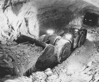
Atlas Copco
Raising
A raise is a vertical or steeply-inclined opening that connects different levels in the mine. It may serve as a ladderway access to stopes, as an ore pass or as an airway in the mine’s ventilation system. Raising is a difficult and dangerous, but necessary job. Raising methods vary from simple manual drill and blast to mechanical rock excavation with raise boring machines (RBMs) (see figure 3).
Figure 3. Raising methods
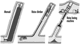
Manual raising
Manual raising is difficult, dangerous and physically demanding work that challenges the miner’s agility, strength and endurance. It is a job to be assigned only to experienced miners in good physical condition. As a rule the raise section is divided into two compartments by a timbered wall. One is kept open for the ladder used for climbing to the face, air pipes, etc. The other fills with rock from blasting which the miner uses as a platform when drilling the round. The timber parting is extended after each round. The work involves ladder climbing, timbering, rock drilling and blasting, all done in a cramped, poorly ventilated space. It is all performed by a single miner, as there is no room for a helper. Mines search for alternatives to the hazardous and laborious manual raising methods.
The raise climber
The raise climber is a vehicle that obviates ladder climbing and much of the difficulty of the manual method. This vehicle climbs the raise on a guide rail bolted to the rock and provides a robust working platform when the miner is drilling the round above. Very high raises can be excavated with the raise climber with safety much improved over the manual method. Raise excavation, however, remains a very hazardous job.
The raise boring machine
The RBM is a powerful machine that breaks the rock mechanically (see figure 4). It is erected on top of the planned raise and a pilot hole about 300 mm in diameter is drilled to break through at a lower level target. The pilot drill is replaced by a reamer head with the diameter of the intended raise and the RBM is put in reverse, rotating and pulling the reamer head upward to create a full-size circular raise.
Figure 4. Raise boring machine
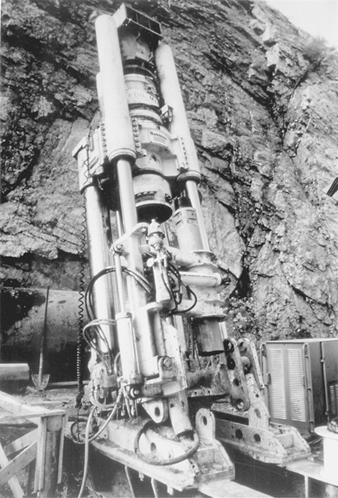
Atlas Copco
Ground control
Ground control is an important concept for people working inside a rock mass. It is particularly important in mechanized mines using rubber-tyred equipment where the drift openings are 25.0 m2 in section, in contrast to the mines with rail drifts where they are usually only 10.0 m2. The roof at 5.0 m is too high for a miner to use a scaling bar to check for potential rock falls.
Different measures are used to secure the roof in underground openings. In smooth blasting, contour holes are drilled closely together and charged with a low-strength explosive. The blast produces a smooth contour without fracturing the outside rock.
Nevertheless, since there are often cracks in the rock mass which do not show on the surface, rock falls are an ever-present hazard. The risk is reduced by rock bolting, i.e., insertion of steel rods in bore holes and fastening them. The rock bolt holds the rock mass together, prevents cracks from spreading, helps to stabilize the rock mass and makes the underground environment safer.
Methods for Underground Mining
The choice of mining method is influenced by the shape and size of the ore deposit, the value of the contained minerals, the composition, stability and strength of the rock mass and the demands for production output and safe working conditions (which sometimes are in conflict). While mining methods have been evolving since antiquity, this article focuses on those used in semi- to fully-mechanized mines during the late twentieth century. Each mine is unique, but they all share the goals of a safe workplace and a profitable business operation.
Flat room-and-pillar mining
Room-and-pillar mining is applicable to tabular mineralization with horizontal to moderate dip at an angle not exceeding 20° (see figure 5). The deposits are often of sedimentary origin and the rock is often in both hanging wall and mineralization in competent (a relative concept here as miners have the option to install rock bolts to reinforce the roof where its stability is in doubt). Room-and-pillar is one of the principal underground coal-mining methods.
Figure 5. Room-and-pillar mining of a flat orebody
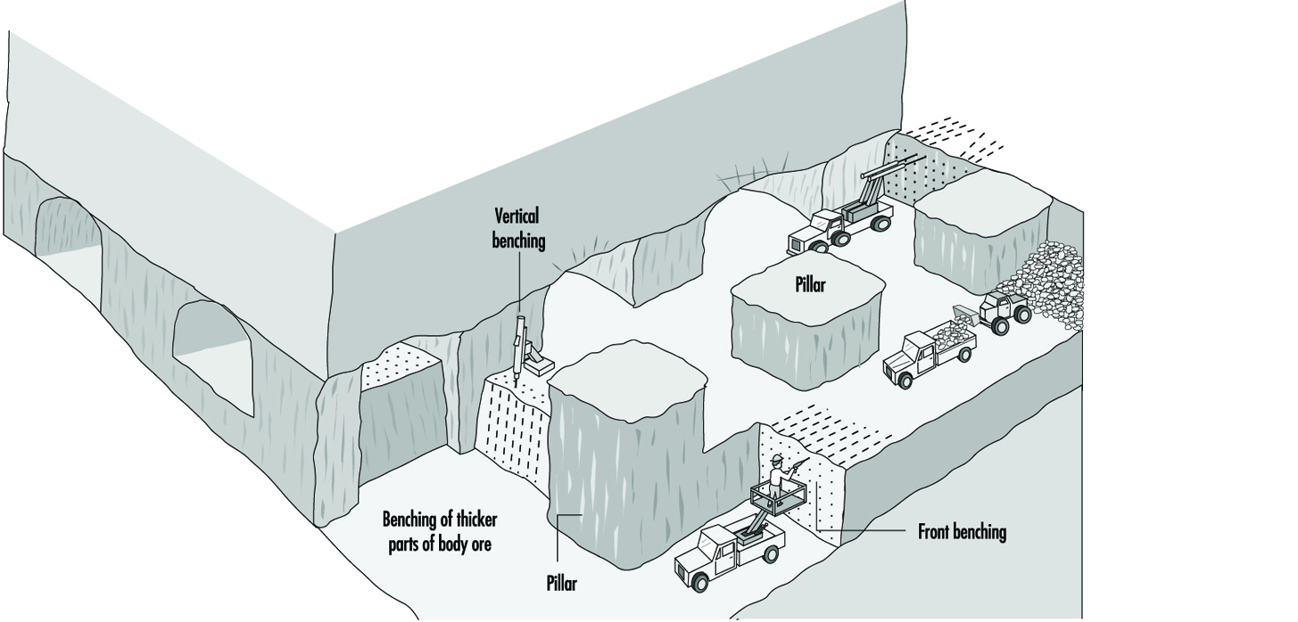
Room-and-pillar extracts an orebody by horizontal drilling advancing along a multi-faced front, forming empty rooms behind the producing front. Pillars, sections of rock, are left between the rooms to keep the roof from caving. The usual result is a regular pattern of rooms and pillars, their relative size representing a compromise between maintaining the stability of the rock mass and extracting as much of the ore as possible. This involves careful analysis of the strength of the pillars, the roof strata span capacity and other factors. Rock bolts are commonly used to increase the strength of the rock in the pillars. The mined-out stopes serve as roadways for trucks transporting the ore to the mine’s storage bin.
The room-and-pillar stope face is drilled and blasted as in drifting. The stope width and height correspond to the size of the drift, which can be quite large. Large productive drill jumbos are used in normal height mines; compact rigs are used where the ore is less than 3.0 m thick. The thick orebody is mined in steps starting from the top so that the roof can be secured at a height convenient for the miners. The section below is recovered in horizontal slices, by drilling flat holes and blasting against the space above. The ore is loaded onto trucks at the face. Normally, regular front-end loaders and dump trucks are used. For the low-height mine, special mine trucks and LHD vehicles are available.
Room-and-pillar is an efficient mining method. Safety depends on the height of the open rooms and ground control standards. The main risks are accidents caused by falling rock and moving equipment.
Inclined room-and-pillar mining
Inclined room-and-pillar applies to tabular mineralization with an angle or dip from 15° and 30° to the horizontal. This is too steep an angle for rubber-tyred vehicles to climb and too flat for a gravity assist rock flow.
The traditional approach to the inclined orebody relies on manual labour. The miners drill blast holes in the stopes with hand-held rock drills. The stope is cleaned with slusher scrapers.
The inclined stope is a difficult place to work. The miners have to climb the steep piles of blasted rock carrying with them their rock drills and the drag slusher pulley and steel wires. In addition to rock falls and accidents, there are the hazards of noise, dust, inadequate ventilation and heat.
Where the inclined ore deposits are adaptable to mechanization, “step-room mining” is used. This is based on converting the “difficult dip” footwall into a “staircase” with steps at an angle convenient for trackless machines. The steps are produced by a diamond pattern of stopes and haulage-ways at the selected angle across the orebody.
Ore extraction starts with horizontal stope drives, branching out from a combined access-haulage drift. The initial stope is horizontal and follows the hanging wall. The next stope starts a short distance further down and follows the same route. This procedure is repeated moving downward to create a series of steps to extract the orebody.
Sections of the mineralization are left to support the hanging wall. This is done by mining two or three adjacent stope drives to the full length and then starting the next stope drive one step down, leaving an elongated pillar between them. Sections of this pillar can later be recovered as cut-outs that are drilled and blasted from the stope below.
Modern trackless equipment adapts well to step-room mining. The stoping can be fully mechanized, using standard mobile equipment. The blasted ore is gathered in the stopes by the LHD vehicles and transferred to mine truck for transport to the shaft/ore pass. If the stope is not high enough for truck loading, the trucks can be filled in special loading bays excavated in the haulage drive.
Shrinkage stoping
Shrinkage stoping may be termed a “classic” mining method, having been perhaps the most popular mining method for most of the past century. It has largely been replaced by mechanized methods but is still used in many small mines around the world. It is applicable to mineral deposits with regular boundaries and steep dip hosted in a competent rock mass. Also, the blasted ore must not be affected by storage in the slopes (e.g., sulphide ores have a tendency to oxidize and decompose when exposed to air).
Its most prominent feature is the use of gravity flow for ore handling: ore from stopes drops directly into rail cars via chutes obviating manual loading, traditionally the most common and least liked job in mining. Until the appearance of the pneumatic rocker shovel in the 1950s, there was no machine suitable for loading rock in underground mines.
Shrinkage stoping extracts the ore in horizontal slices, starting at the stope bottoms and advancing upwards. Most of the blasted rock remains in the stope providing a working platform for the miner drilling holes in the roof and serving to keep the stope walls stable. As blasting increases the volume of the rock by about 60%, some 40% of the ore is drawn at the bottom during stoping in order to maintain a work space between the top of the muckpile and the roof. The remaining ore is drawn after blasting has reached the upper limit of the stope.
The necessity of working from the top of the muckpile and the raise-ladder access prevents the use of mechanized equipment in the stope. Only equipment light enough for the miner to handle alone may be used. The air-leg and rock drill, with a combined weight of 45 kg, is the usual tool for drilling the shrinkage stope. Standing on top of the muckpile, the miner picks up the drill/feed, anchors the leg, braces the rock drill/drill steel against the roof and starts drilling; it is not easy work.
Cut-and-fill mining
Cut-and-fill mining is suitable for a steeply dipping mineral deposit contained in a rock mass with good to moderate stability. It removes the ore in horizontal slices starting from a bottom cut and advances upwards, allowing the stope boundaries to be adjusted to follow irregular mineralization. This permits high-grade sections to be mined selectively, leaving low-grade ore in place.
After the stope is mucked clean, the mined out space is backfilled to form a working platform when the next slice is mined and to add stability to the stope walls.
Development for cut-and-fill mining in a trackless environment includes a footwall haulage drive along the orebody at the main level, undercut of the stope provided with drains for the hydraulic backfill, a spiral ramp excavated in the footwall with access turn-outs to the stopes and a raise from the stope to the level above for ventilation and fill transport.
Overhand stoping is used with cut-and-fill, with both dry rock and hydraulic sand as backfill material. Overhand means that the ore is drilled from below by blasting a slice 3.0 m to 4.0 m thick. This allows the complete stope area to be drilled and the blasting of the full stope without interruptions. The “uppers” holes are drilled with simple wagon drills.
Up-hole drilling and blasting leaves a rough rock surface for the roof; after mucking out, its height will be about 7.0 m. Before miners are allowed to enter the area, the roof must be secured by trimming the roof contours with smooth-blasting and subsequent scaling of the loose rock. This is done by miners using hand-held rock drills working from the muckpile.
In front stoping, trackless equipment is used for ore production. Sand tailings are used for backfill and distributed in the underground stopes via plastic pipes. The stopes are filled almost completely, creating a surface sufficiently hard to be traversed by rubber-tyred equipment. The stope production is completely mechanized with drifting jumbos and LHD vehicles. The stope face is a 5.0 m vertical wall across the stope with a 0.5 m open slot beneath it. Five-meter-long horizontal holes are drilled in the face and ore is blasted against the open bottom slot.
The tonnage produced by a single blast depends on the face area and does not compare to that yielded by the overhand stope blast. However, the output of trackless equipment is vastly superior to the manual method, while roof control can be accomplished by the drill jumbo which drills smooth-blast holes together with the stope blast. Fitted with an oversize bucket and large tyres, the LHD vehicle, a versatile tool for mucking and transport, travels easily on the fill surface. In a double face stope, the drill jumbo engages it on one side while the LHD handles the muckpile at the other end, providing efficient use of the equipment and enhancing the production output.
Sublevel stoping removes ore in open stopes. Backfilling of stopes with consolidated fill after the mining allows the miners to return at a later time to recover the pillars between the stopes, enabling a very high recovery rate of the mineral deposit.
Development for sublevel stoping is extensive and complex. The orebody is divided into sections with a vertical height of about 100 m in which sublevels are prepared and connected via an inclined ramp. The orebody sections are further divided laterally in alternating stopes and pillars and a mail haulage drive is created in the footwall, at the bottom, with cut-outs for drawpoint loading.
When mined out, the sublevel stope will be a rectangular opening across the orebody. The bottom of the stope is V-shaped to funnel the blasted material into the draw-points. Drilling drifts for the long-hole rig are prepared on the upper sublevels (see figure 6).
Figure 6. Sublevel stoping using ring drilling & cross-cut loading
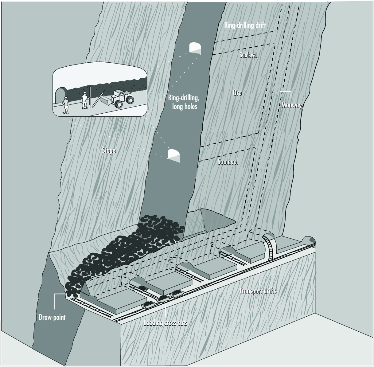
Blasting requires space for the rock to expand in volume. This requires that a slot a few metres wide be prepared before the start of long-hole blasting. This is accomplished by enlarging a raise from the bottom to the top of the stope to a full slot.
After opening the slot, the long-hole rig (see figure 7) begins production drilling in sublevel drifts following precisely a detailed plan designed by blasting experts which specifies all the blast holes, the collaring position, depth and direction of the holes. The drill rig continues drilling until all the rings on one level are completed. It is then transferred to the next sublevel to continue drilling. Meanwhile the holes are charged and a blast pattern which covers a large area within the stope breaks up a large volume of ore in one blast. The blasted ore drops to the stope bottom to be recovered by the LHD vehicles mucking in the draw-point beneath the stope. Normally, the long-hole drilling stays ahead of the charging and blasting providing a reserve of ready-to-blast ore, thus making for an efficient production schedule.
Figure 7. Long-hole drill rig
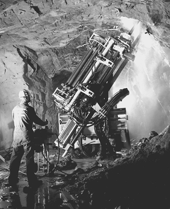
Atlas Copco
Sublevel stoping is a productive mining method. Efficiency is enhanced by the ability to use fully mechanized productive rigs for the long-hole drilling plus the fact that the rig can be used continuously. It is also relatively safe because doing the drilling inside sublevel drifts and mucking through draw-points eliminates exposure to potential rock falls.
Vertical crater retreat mining
Like sublevel stoping and shrinkage stoping, vertical crater retreat (VCR) mining is applicable to mineralization in steeply dipping strata. However, it uses a different blasting technique breaking the rock with heavy, concentrated charges placed in holes (“craters”) with very large diameter (about 165 mm) about 3 m away from a free rock surface. Blasting breaks a cone-shaped opening in the rock mass around the hole and allows the blasted material to remain in the stope during the production phase so that the rock fill can assist in supporting the stope walls. The need for rock stability is less than in sublevel stoping.
The development for VCR mining is similar to that for sublevel stoping except for requiring both over-cut and under-cut excavations. The over-cut is needed in the first stage to accommodate the rig drilling the large-diameter blast holes and for access while charging the holes and blasting. The under-cut excavation provided the free surface necessary for VCR blasting. It may also provide access for a LHD vehicle (operated by remote control with the operator remaining outside the stope) to recover the blasted ore from the draw-points beneath the stope.
The usual VCR blast uses holes in a 4.0 × 4.0 m pattern directed vertically or steeply inclined with charges carefully placed at calculated distances to free the surface beneath. The charges cooperate to break off a horizontal ore slice about 3.0 m thick. The blasted rock falls into the stope underneath. By controlling the rate of mucking out, the stope remains partly filled so that the rock fill assists in stabilizing the stope walls during the production phase. The last blast breaks the over-cut into the stope, after which the stope is mucked clean and prepared for back filling.
VCR mines often uses a system of primary and secondary stopes to the orebody. Primary stopes are mined in the first stage, then backfilled with cemented fill. The stope is left for the fill to consolidate. Miners then return and recover the ore in the pillars between the primary stopes, the secondary stopes. This system, in combination with the cemented backfill, results in close to a 100% recovery of the ore reserves.
Sublevel caving
Sublevel caving is applicable to mineral deposits with steep to moderate dip and large extension at depth. The ore must fracture into manageable block with blasting. The hanging wall will cave following the ore extraction and the ground on the surface above the orebody will subside. (It must be barricaded to prevent any individuals from entering the area.)
Sublevel caving is based on gravity flow inside a broken-up rock mass containing both ore and rock. The rock mass is first fractured by drilling and blasting and then mucked out through drift headings underneath the rock mass cave. It qualifies as a safe mining method because the miners always work inside drift-size openings.
Sublevel caving depends on sublevels with regular patterns of drifts prepared inside the orebody at rather close vertical spacing (from 10.0 m to 20 0 m). The drift layout is the same on each sublevel (i.e., parallel drives across the orebody from the footwall transport drive to the hanging wall) but the patterns on each sublevel are slightly off-set so that the drifts on a lower level are located between the drifts on the sublevel above it. A cross section will show a diamond pattern with drifts in regular vertical and horizontal spacing. Thus, development for sublevel caving is extensive. Drift excavation, however, is a straightforward task which can readily be mechanized. Working on multiple drift headings on several sublevels favours high utilization of the equipment.
When the development of the sublevel is completed, the long-hole drill rig moves in to drill a blast holes in a fan-spread pattern in the rock above. When all of the blast holes are ready, the long-hole drill rig is moved to the sublevel below.
The long-hole blast fractures the rock mass above the sublevel drift, initiating a cave that starts at the hanging wall contact and retreats toward the footwall following a straight front across the orebody on the sublevel. A vertical section would show a staircase where each upper sublevel is one step ahead of the sublevel below.
The blast fills the sublevel front with a mix of ore and waste. When the LHD vehicle arrives, the cave contains 100% ore. As loading continues, the proportion of waste rock will gradually increase until the operator decides that the waste dilution is too high and stops loading. As the loader moves to the next drift to continue mucking, the blaster enters to prepare the next ring of holes for blasting.
Mucking out on sublevels is an ideal application for the LHD vehicle. Available in different sizes to meet particular situations, it fills the bucket, travels some 200 m, empties the bucket into the ore pass and returns for another load.
Sublevel caving features a schematic layout with repetitive work procedures (development drifting, long-hole drilling, charging and blasting, loading and transport) that are carried out independently. This allows the procedures to move continuously from one sublevel to another, allowing for the most efficient use of work crews and equipment. In effect the mine is analogous to a departmentalized factory. Sublevel mining, however, being less selective than other methods, does not yield particularly efficient extraction rates. The cave includes some 20 to 40% of waste with a loss of ore that ranges from 15 to 25%.
Block-caving
Block-caving is a large-scale method applicable to mineralization on the order of 100 million tonnes in all directions contained in rock masses amenable to caving (i.e., with internal stresses which, after removal of the supporting elements in the rock mass, assist the fracturing of the mined block). An annual output ranging from 10 to 30 million tonnes is the anticipated yield. These requirements limit block-caving to a few specific mineral deposits. Worldwide, there are block-caving mines exploiting deposits containing copper, iron, molybdenum and diamonds.
Block refers to the mining layout. The orebody is divided into large sections, blocks, each containing a tonnage sufficient for many years of production. The caving is induced by removing the supporting strength of the rock mass directly underneath the block by means of an undercut, a 15 m high section of rock fractured by long-hole drilling and blasting. Stresses created by natural tectonic forces of considerable magnitude, similar to those causing continental movements, create cracks in the rock mass, breaking the blocks, hopefully to pass draw-point openings in the mine. Nature, though, often needs the assistance of miners to handle oversize boulders.
Preparation for block-caving requires long-range planning and extensive initial development involving a complex system of excavations beneath the block. These vary with the site; they generally include undercut, drawbells, grizzlies for control of oversize rock and ore passes that funnel the ore into train loading.
Drawbells are conical openings excavated underneath the undercut which gather ore from a large area and funnel it into the drawpoint at the production level below. Here the ore is recovered in LHD vehicles and transferred to ore passes. Boulders too large for the bucket are blasted in draw-points, while smaller ones are dealt with on the grizzly. Grizzlies, sets of parallel bars for screening coarse material, are commonly used in block-caving mines although, increasingly, hydraulic breakers are being preferred.
Openings in a block-caving mine are subject to high rock pressure. Drifts and other openings, therefore, are excavated with the smallest possible section. Nevertheless, extensive rock bolting and concrete lining is required to keep the openings intact.
Properly applied, block-caving is a low-cost, productive mass mining method. However, the amenability of a rock mass to caving is not always predictable. Also, the comprehensive development that is required results in a long lead-time before the mine starts producing: the delay in earnings can have a negative influence on the financial projections used to justify the investment.
Longwall mining
Longwall mining is applicable to bedded deposits of uniform shape, limited thickness and large horizontal extension (e.g., a coal seam, a potash layer or the reef, the bed of quartz pebbles exploited by gold mines in South Africa). It is one of the main methods for mining coal. It recovers the mineral in slices along a straight line that are repeated to recover materials over a larger area. The space closest to the face in kept open while the hanging wall is allowed to collapse at a safe distance behind the miners and their equipment.
Preparation for longwall mining involves the network of drifts required for access to the mining area and transport of the mined product to the shaft. Since the mineralization is in the form of a sheet that extends over a wide area, the drifts can usually be arranged in a schematic network pattern. The haulage drifts are prepared in the seam itself. The distance between two adjacent haulage drifts determines the length of the longwall face.
Backfilling
Backfilling of mine stopes prevents rock from collapsing. It preserves the inherent stability of the rock mass which promotes safety and allows more complete extraction of the desired ore. Backfilling is traditionally used with cut-and-fill but it is also common with sublevel stoping and VCR mining.
Traditionally, miners have dumped waste rock from development in empty stopes instead of hauling it to the surface. For example, in cut-and-fill, waste rock is distributed over the empty stope by scrapers or bulldozers.
Hydraulic backfilling uses tailings from the mine’s dressing plant which are distributed underground through bore holes and plastic tubing. The tailings are first de-slimed, only the coarse fraction being used for filling. The fill is a mix of sand and water, about 65% of which is solid matter. By mixing cement into the last pour, the fill’s surface will harden into a smooth roadbed for rubber-tyred equipment.
Backfilling is also used with sublevel stoping and VCR mining, with crushed rock introduced as a complement to sand fill. The crushed and screened rock, produced in a nearby quarry, is delivered underground through special backfill raises where it is loaded on trucks and delivered to the stopes where it is dumped into special fill raises. Primary stopes are backfilled with cemented rock fill produced by spraying a cement-fly ash slurry on the rockfill before it is distributed to the stopes. The cemented rockfill hardens into a solid mass forming an artificial pillar for mining the secondary stope. The cement slurry is generally not required when secondary stopes are backfilled, except for the last pours to establish a firm mucking floor.
Equipment for Underground Mining
Underground mining is becoming increasingly mechanized wherever circumstances permit. The rubber-tyred, diesel-powered, four-wheel traction, articulated steer carrier is common to all mobile underground machines (see figure 8).
Figure 8. Small-size face rig

Atlas Copco
Face drill jumbo for development drilling
This is an indispensable workhorse in mines that is used for all rock excavation work. It carries one or two booms with hydraulic rock drills. With one worker at the control panel, it will complete a pattern of 60 blast holes 4.0 m deep in a few hours.
Long-hole production drill rig
This rig (see figure 7 drills blast holes in a radial spread around the drift which cover a large area of rock and break off large volumes of ore. It is used with sublevel stoping, sublevel caving, block-caving and VCR mining. With a powerful hydraulic rock drill and carousel storage for extension rods, the operator uses remote controls to perform rock drilling from a safe position.
Charging truck
The charging truck is a necessary complement to the drifting jumbo. The carrier mounts a hydraulic service platform, a pressurized ANFO explosive container and a charging hose that permit the operator to fill blast holes all over the face in a very short time. At the same time, Nonel detonators may be inserted for the correct timing of the individual blasts.
LHD vehicle
The versatile load-haul-dump vehicle (see figure 10) is used for a variety of services including ore production and materials handling. It is available in a choice of sizes allowing miners to select the model most appropriate for each task and each situation. Unlike the other diesel vehicles used in mines, the LHD vehicle engine is generally run continuously at full power for long periods of time generating large volumes of smoke and exhaust fumes. A ventilation system capable of diluting and exhausting these fumes is essential to compliance with acceptable breathing standards in the loading area.
Underground haulage
The ore recovered in stopes spread along an orebody is transported to an ore dump located close to the hoisting shaft. Special haulage levels are prepared for longer lateral transfer; they commonly feature rail track installations with trains for ore transport. Rail has proved to be an efficient transport system carrying larger volumes for longer distances with electric locomotives that do not contaminate the underground atmosphere like diesel-powered trucks used in trackless mines.
Ore handling
On its route from the stopes to the hoisting shaft, the ore passes several stations with a variety of materials-handling techniques.
The slusher uses a scraper bucket to draw ore from the stope to the ore pass. It is equipped with rotating drums, wires and pulleys, arranged to produce a back and forth scraper route. The slusher does not need preparation of the stope flooring and can draw ore from a rough muckpile.
The LHD vehicle, diesel powered and travelling on rubber tyres, takes the volume held in its bucket (sizes vary) from the muckpile to the ore pass.
The ore pass is a vertical or steeply inclined opening through which rock flows by gravity from upper to lower levels. Ore passes are sometimes arranged in a vertical sequence to collect ore from upper levels to a common delivery point on the haulage level.
The chute is the gate located at the bottom of the ore pass. Ore passes normally end in rock close to the haulage drift so that, when the chute is opened, the ore can flow to fill cars on the track beneath it.
Close to the shaft, the ore trains pass a dump station where the load may be dropped into a storage bin, A grizzly at the dump station stops oversized rocks from falling into the bin. These boulders are split by blasting or hydraulic hammers; a coarse crusher may be installed below the grizzly for further size control. Under the storage bin is a measure pocket which automatically verifies that the load’s volume and weight do not exceed the capacities of the skip and the hoist. When an empty skip, a container for vertical travel, arrives at the filling station, a chute opens in the bottom of the measure pocket filling the skip with a proper load. After the hoist lifts the loaded skip to the headframe on the surface, a chute opens to discharge the load into the surface storage bin. Skip hoisting can be automatically operated using closed-circuit television to monitor the process.
Types of Coal Mining
The rationale for selecting a method for mining coal depends on such factors as topography, geometry of the coal seam, geology of the overlying rocks and environmental requirements or restraints. Overriding these, however, are the economic factors. They include: availability, quality and costs of the required work force (including the availability of trained supervisors and managers); adequacy of housing, feeding and recreational facilities for the workers (especially when the mine is located at a distance from a local community); availability of the necessary equipment and machinery and of workers trained to operate it; availability and costs of transportation for workers, necessary supplies, and for getting the coal to the user or purchaser; availability and the cost of the necessary capital to finance the operation (in local currency); and the market for the particular type of coal to be extracted (i.e., the price at which it may be sold). A major factor is the stripping ratio, that is, the amount of overburden material to be removed in proportion to the amount of coal that can be extracted; as this increases, the cost of mining becomes less attractive. An important factor, especially in surface mining, that, unfortunately, is often overlooked in the equation, is the cost of restoring the terrain and the environment when the mining operation is closed down.
Health and Safety
Another critical factor is the cost of protecting the health and safety of the miners. Unfortunately, particularly in small-scale operations, instead of being weighed in deciding whether or how the coal should be extracted, the necessary protective measures are often ignored or short-changed.
Actually, although there are always unsuspected hazards—they may come from the elements rather than the mining operations—any mining operation can be safe providing there is a commitment from all parties to a safe operation.
Surface Coal Mines
Surface mining of coal is performed by a variety of methods depending on the topography, the area in which the mining is being undertaken and environmental factors. All methods involve the removal of overburden material to allow for the extraction of the coal. While generally safer than underground mining, surface operations do have some specific hazards that must be addressed. Prominent among these is the use of heavy equipment which, in addition to accidents, may involve exposure to exhaust fumes, noise and contact with fuel, lubricants and solvents. Climatic conditions, such as heavy rain, snow and ice, poor visibility and excessive heat or cold may compound these hazards. When blasting is required to break up rock formations, special precautions in the storage, handling and use of explosives are required.
Surface operations require the use of huge waste dumps to store overburden products. Appropriate controls must be implemented to prevent dump failure and to protect the employees, the general public and the environment.
Underground Mining
There is also a variety of methods for underground mining. Their common denominator is the creation of tunnels from the surface to the coal seam and the use of machines and/or explosives to extract the coal. In addition to the high frequency of accidents—coal mining ranks high on the list of hazardous workplaces wherever statistics are maintained—the potential for a major incident involving multiple loss of life is always present in underground operations. Two primary causes of such catastrophes are cave-ins due to faulty engineering of the tunnels and explosion and fire due to the accumulation of methane and/or flammable levels of airborne coal dust.
Methane
Methane is highly explosive in concentrations of 5 to 15% and has been the cause of numerous mining disasters. It is best controlled by providing adequate air flow to dilute the gas to a level that is below its explosive range and to exhaust it quickly from the workings. Methane levels must be continuously monitored and rules established to close down operations when its concentration reaches 1 to 1.5% and to evacuate the mine promptly if it reaches levels of 2 to 2.5%.
Coal dust
In addition to causing black lung disease (anthracosis) if inhaled by miners, coal dust is explosive when fine dust is mixed with air and ignited. Airborne coal dust can be controlled by water sprays and exhaust ventilation. It can be collected by filtering recirculating air or it can be neutralized by the addition of stone dust in sufficient quantities to render the coal dust/air mixture inert.
Exploration
Mineral exploration is the precursor to mining. Exploration is a high-risk, high-cost business that, if successful, results in the discovery of a mineral deposit that can be mined profitably. In 1992, US$1.2 billion was spent worldwide on exploration; this increased to almost US$2.7 billion in 1995. Many countries encourage exploration investment and competition is high to explore in areas with good potential for discovery. Almost without exception, mineral exploration today is carried out by interdisciplinary teams of prospectors, geologists, geophysicists and geochemists who search for mineral deposits in all terrain throughout the world.
Mineral exploration begins with a reconnaissance or generative stage and proceeds through a target evaluation stage, which, if successful, leads to advanced exploration. As a project progresses through the various stages of exploration, the type of work changes as do health and safety issues.
Reconnaissance field work is often conducted by small parties of geoscientists with limited support in unfamiliar terrain. Reconnaissance may comprise prospecting, geologic mapping and sampling, wide-spaced and preliminary geochemical sampling and geophysical surveys. More detailed exploration commences during the target testing phase once land is acquired through permit, concession, lease or mineral claims. Detailed field work comprising geologic mapping, sampling and geophysical and geochemical surveys requires a grid for survey control. This work frequently yields targets that warrant testing by trenching or drilling, entailing the use of heavy equipment such as back-hoes, power shovels, bulldozers, drills and, occasionally, explosives. Diamond, rotary or percussion drill equipment may be truck-mounted or may be hauled to the drill site on skids. Occasionally helicopters are used to sling drills between drill sites.
Some project exploration results will be sufficiently encouraging to justify advanced exploration requiring the collection of large or bulk samples to evaluate the economic potential of a mineral deposit. This may be accomplished through intensive drilling, although for many mineral deposits some form of trenching or underground sampling may be necessary. An exploration shaft, decline or adit may be excavated to gain underground access to the deposit. Although the actual work is carried out by miners, most mining companies will ensure that an exploration geologist is responsible for the underground sampling programme.
Health and Safety
In the past, employers seldom implemented or monitored exploration safety programmes and procedures. Even today, exploration workers frequently have a cavalier attitude towards safety. As a result, health and safety issues may be overlooked and not considered an integral part of the explorer’s job. Fortunately, many mining exploration companies now strive to change this aspect of the exploration culture by requiring that employees and contractors follow established safety procedures.
Exploration work is often seasonal. Consequently there are pressures to complete work within a limited time, sometimes at the expense of safety. In addition, as exploration work progresses to later stages, the number and variety of risks and hazards increase. Early reconnaissance field work requires only a small field crew and camp. More detailed exploration generally requires larger field camps to accommodate a greater number of employees and contractors. Safety issues—especially training on personal health issues, camp and worksite hazards, the safe use of equipment and traverse safety—become very important for geoscientists who may not have had previous field work experience.
Because exploration work is often carried out in remote areas, evacuation to a medical treatment centre may be difficult and may depend on weather or daylight conditions. Therefore, emergency procedures and communications should be carefully planned and tested before field work commences.
While outdoor safety may be considered common sense or “bush sense”, one should remember that what is considered common sense in one culture may not be so considered in another culture. Mining companies should provide exploration employees with a safety manual that addresses the issues of the regions where they work. A comprehensive safety manual can form the basis for camp orientation meetings, training sessions and routine safety meetings throughout the field season.
Preventing personal health hazards
Exploration work subjects employees to hard physical work that includes traversing terrain, frequent lifting of heavy objects, using potentially dangerous equipment and being exposed to heat, cold, precipitation and perhaps high altitude (see figure 1). It is essential that employees be in good physical condition and in good health when they begin field work. Employees should have up-to-date immunizations and be free of communicable diseases (e.g., hepatitis and tuberculosis) that may rapidly spread through a field camp. Ideally, all exploration workers should be trained and certified in basic first aid and wilderness first-aid skills. Larger camps or worksites should have at least one employee trained and certified in advanced or industrial first-aid skills.
Figure 1. Drilling in mountains in British Columbia, Canada, with a light Winkie drill
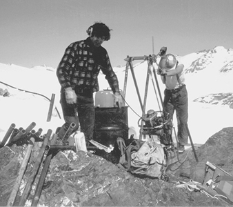
William S. Mitchell
Outdoor workers should wear suitable clothing that protects them from extremes of heat, cold and rain or snow. In regions with high levels of ultraviolet light, workers should wear a broad-brimmed hat and use a sunscreen lotion with a high sun protection factor (SPF) to protect exposed skin. When insect repellent is required, repellent that contains DEET (N,N-diethylmeta-toluamide) is most effective in preventing bites from mosquitoes. Clothing treated with permethrin helps protect against ticks.
Training. All field employees should receive training in such topics as lifting, the correct use of approved safety equipment (e.g., safety glasses, safety boots, respirators, appropriate gloves) and health precautions needed to prevent injury due to heat stress, cold stress, dehydration, ultraviolet light exposure, protection from insect bites and exposure to any endemic diseases. Exploration workers who take assignments in developing countries should educate themselves about local health and safety issues, including the possibility of kidnapping, robbery and assault.
Preventive measures for the campsite
Potential health and safety issues will vary with the location, size and type of work performed at a camp. Any field campsite should meet local fire, health, sanitation and safety regulations. A clean, orderly camp will help reduce accidents.
Location. A campsite should be established as close as safely possible to the worksite to minimize travel time and exposure to dangers associated with transportation. A campsite should be located away from any natural hazards and take into consideration the habits and habitat of wild animals that may invade a camp (e.g., insects, bears and reptiles). Whenever possible, camps should be near a source of clean drinking water (see figure 2). When working at very high altitude, the camp should be located at a lower elevation to help prevent altitude sickness.
Figure 2. Summer field camp, Northwest Territories, Canada
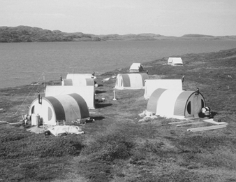
William S. Mitchell
Fire control and fuel handling. Camps should be set up so that tents or structures are well spaced to prevent or reduce the spread of fire. Fire-fighting equipment should be kept in a central cache and appropriate fire extinguishers kept in kitchen and office structures. Smoking regulations help prevent fires both in camp and in the field. All workers should participate in fire drills and know the plans for fire evacuation. Fuels should be accurately labelled to ensure that the correct fuel is used for lanterns, stoves, generators and so on. Fuel caches should be located at least 100 m from camp and above any potential flood or tide level.
Sanitation. Camps require a supply of safe drinking water. The source should be tested for purity, if required. When necessary, drinking water should be stored in clean, labelled containers separate from non-potable water. Food shipments should be examined for quality upon arrival and immediately refrigerated or stored in containers to prevent invasions from insects, rodents or larger animals. Handwashing facilities should be located near eating areas and latrines. Latrines must conform to public health standards and should be located at least 100 m away from any stream or shoreline.
Camp equipment, field equipment and machinery. All equipment (e.g., chain saws, axes, rock hammers, machetes, radios, stoves, lanterns, geophysical and geochemical equipment) should be kept in good repair. If firearms are required for personal safety from wild animals such as bears, their use must be strictly controlled and monitored.
Communication. It is important to establish regular communication schedules. Good communication increases morale and security and forms a basis for an emergency response plan.
Training. Employees should be trained in the safe use all equipment. All geophysicists and helpers should be trained to use ground (earth) geophysical equipment that may operate at high current or voltage. Additional training topics should include fire prevention, fire drills, fuel handling and firearms handing, when relevant.
Preventive measures at the worksite
The target testing and advanced stages of exploration require larger field camps and the use of heavy equipment at the worksite. Only trained workers or authorized visitors should be permitted onto worksites where heavy equipment is operating.
Heavy equipment. Only properly licensed and trained personnel may operate heavy equipment. Workers must be constantly vigilant and never approach heavy equipment unless they are certain the operator knows where they are, what they intend to do and where they intend to go.
Figure 3. Truck-mounted drill in Australia
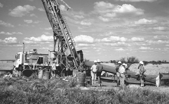
Williams S. Mitchll
Drill rigs. Crews should be fully trained for the job. They must wear appropriate personal protective equipment (e.g., hard hats, steel-toed boots, hearing protection, gloves, goggles and dust masks) and avoid wearing loose clothing that may become caught in machinery. Drill rigs should comply with all safety requirements (e.g., guards that cover all moving parts of machinery, high pressure air hoses secured with clamps and safety chains) (see figure 3). Workers should be aware of slippery, wet, greasy, or icy conditions underfoot and the drill area kept as orderly as possible (see figure 4).
Figure 4. Reverse circulation drilling on a frozen lake in Canada
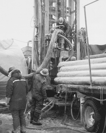
William S. Mitchell
Excavations. Pits and trenches should be constructed to meet safety guidelines with support systems or the sides cut back to 45º to deter collapse. Workers should never work alone or remain alone in a pit or trench, even for a short period of time, as these excavations collapse easily and may bury workers.
Explosives. Only trained and licensed personnel should handle explosives. Regulations for handling, storage and transportation of explosives and detonators should be carefully followed.
Preventive measures in traversing terrain
Exploration workers must be prepared to cope with the terrain and climate of their field area. The terrain may include deserts, swamps, forests, or mountainous terrain of jungle or glaciers and snowfields. Conditions may be hot or cold and dry or wet. Natural hazards may include lightning, bush fires, avalanches, mudslides or flash floods and so on. Insects, reptiles and/or large animals may present life-threatening hazards.
Workers must not take chances or place themselves in danger to secure samples. Employees should receive training in safe traversing procedures for the terrain and climate conditions where they work. They need survival training to recognize and combat hypothermia, hyperthermia and dehydration. Employees should work in pairs and carry enough equipment, food and water (or have access in an emergency cache) to enable them to spend an unexpected night or two out in the field if an emergency situation arises. Field workers should maintain routine communication schedules with the base camp. All field camps should have established and tested emergency response plans in case field workers need rescuing.
Preventive measures in transportation
Many accidents and incidents occur during transportation to or from an exploration worksite. Excessive speed and/or alcohol consumption while driving vehicles or boats are relevant safety issues.
Vehicles. Common causes of vehicle accidents include hazardous road and/or weather conditions, overloaded or incorrectly loaded vehicles, unsafe towing practices, driver fatigue, inexperienced drivers and animals or people on the road—especially at night. Preventive measures include following defensive driving techniques when operating any type of vehicle. Drivers and passengers of cars and trucks must use seatbelts and follow safe loading and towing procedures. Only vehicles that can safely operate in the terrain and weather conditions of the field area, e.g., 4-wheel drive vehicles, 2-wheel motor bikes, all-terrain vehicles (ATVs) or snowmobiles should be used (see figure 5). Vehicles must have regular maintenance and contain adequate equipment including survival gear. Protective clothing and a helmet are required when operating ATVs or 2-wheel motor bikes.
Figure 5. Winter field transportation in Canada
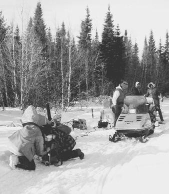
William S. Mitchell
Aircraft. Access to remote sites frequently depends on fixed wing aircraft and helicopters (see figure 6). Only charter companies with well-maintained equipment and a good safety record should be engaged. Aircraft with turbine engines are recommended. Pilots must never exceed the legal number of allowable flight hours and should never fly when fatigued or be asked to fly in unacceptable weather conditions. Pilots must oversee the proper loading of all aircraft and comply with payload restrictions. To prevent accidents, exploration workers must be trained to work safely around aircraft. They must follow safe embarkation and loading procedures. No one should walk in the direction of the propellers or rotor blades; they are invisible when moving. Helicopter landing sites should be kept free of loose debris that may become airborne projectiles in the downdraft of rotor blades.
Figure 6. Unloading field supplies from Twin Otter, Northwest Territories, Canada
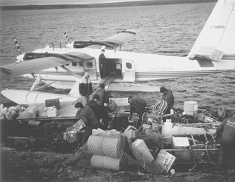
William S. Mitchell
Slinging. Helicopters are often used to move supplies, fuel, drill and camp equipment. Some major hazards include overloading, incorrect use of or poorly maintained slinging equipment, untidy worksites with debris or equipment that may be blown about, protruding vegetation or anything that loads may snag on. In addition, pilot fatigue, lack of personnel training, miscommunication between parties involved (especially between the pilot and groundman) and marginal weather conditions increase the risks of slinging. For safe slinging and to prevent accidents, all parties must follow safe slinging procedures and be fully alert and well briefed with mutual responsibilities clearly understood. The sling cargo weight must not exceed the lifting capacity of the helicopter. Loads should be arranged so they are secure and nothing will slip out of the cargo net. When slinging with a very long line (e.g., jungle, mountainous sites with very tall trees), a pile of logs or large rocks should be used to weigh down the sling for the return trip because one should never fly with empty slings or lanyards dangling from the sling hook. Fatal accidents have occurred when unweighted lanyards have struck the helicopter tail or main rotor during flight.
Boats. Workers who rely on boats for field transportation on coastal waters, mountain lakes, streams or rivers may face hazards from winds, fog, rapids, shallows, and submerged or semi-submerged objects. To prevent boating accidents, operators must know and not exceed the limitations of their boat, their motor and their own boating capabilities. The largest, safest boat available for the job should be used. All workers should wear a good quality personal flotation device (PFD) whenever travelling and/or working in small boats. In addition, all boats must contain all legally required equipment plus spare parts, tools, survival and first aid equipment and always carry and use up-to-date charts and tide tables.
Mining: An Overview
Minerals and mineral products are the backbone of most industries. Some form of mining or quarrying is carried out in virtually every country in the world. Mining has important economic, environmental, labour and social effects—both in the countries or regions where it is carried out and beyond. For many developing countries mining accounts for a significant proportion of GDP and, often, for the bulk of foreign exchange earnings and foreign investment.
The environmental impact of mining can be significant and long-lasting. There are many examples of good and bad practice in the management and rehabilitation of mined areas. The environmental effect of the use of minerals is becoming an important issue for the industry and its workforce. The debate on global warming, for example, could affect the use of coal in some areas; recycling lessens the amount of new material required; and the increasing use of non-mineral materials, such as plastics, affects the intensity of use of metals and minerals per unit of GDP.
Competition, declining mineral grades, higher treatment costs, privatization and restructuring are each putting pressure on mining companies to reduce their costs and increase their productivity. The high capital intensity of much of the mining industry encourages mining companies to seek the maximum use of their equipment, calling in turn for more flexible and often more intensive work patterns. Employment is falling in many mining areas due to increased productivity, radical restructuring and privatization. These changes not only affect mineworkers who must find alternative employment; those remaining in the industry are required to have more skills and more flexibility. Finding the balance between the desire of mining companies to cut costs and those of workers to safeguard their jobs has been a key issue throughout the world of mining. Mining communities must also adapt to new mining operations, as well as to downsizing or closure.
Mining is often considered to be a special industry involving close-knit communities and workers doing a dirty, dangerous job. Mining is also a sector where many at the top—managers and employers—are former miners or mining engineers with wide, first-hand experience of the issues that affect their enterprises and workforces. Moreover, mineworkers have often been the elite of industrial workers and have frequently been at the forefront when political and social changes have taken place faster than was envisaged by the government of the day.
About 23 billion tonnes of minerals, including coal, are produced each year. For high-value minerals, the quantity of waste produced is many times that of the final product. For example, each ounce of gold is the result of dealing with about 12 tonnes of ore; each tonne of copper comes from about 30 tonnes of ore. For lower value materials (e.g., sand, gravel and clay)—which account for the bulk of the material mined—the amount of waste material that can be tolerated is minimal. It is safe to assume, however, that the world’s mines must produce at least twice the final amount required (excluding the removal of surface “overburden”, which is subsequently replaced and therefore handled twice). Globally, therefore, some 50 billion tonnes of ore are mined each year. This is the equivalent of digging a 1.5 metre deep hole the size of Switzerland every year.
Employment
Mining is not a major employer. It accounts for about 1% of the world’s workforce—some 30 million people, 10 million of whom produce coal. However, for every mining job there is at least one job that is directly dependent on mining. In addition, it is estimated that at least 6 million people not included in the above figure work in small-scale mines. When one takes dependants into account, the number of people relying on mining for a living is likely to be about 300 million.
Safety and Health
Mineworkers face a constantly changing combination of workplace circumstances, both daily and throughout the work shift. Some work in an atmosphere without natural light or ventilation, creating voids in the earth by removing material and trying to ensure that there will be no immediate reaction from the surrounding strata. Despite the considerable efforts in many countries, the toll of death, injury and disease among the world’s mineworkers means that, in most countries, mining remains the most hazardous occupation when the number of people exposed to risk is taken into account.
Although only accounting for 1% of the global workforce, mining is responsible for about 8% of fatal accidents at work (around 15,000 per year). No reliable data exist as far as injuries are concerned, but they are significant, as is the number of workers affected by occupational diseases (such as pneumoconioses, hearing loss and the effects of vibration) whose premature disability and even death can be directly attributed to their work.
The ILO and Mining
The International Labour Organization (ILO) has been dealing with labour and social problems of the mining industry since its early days, making considerable efforts to improve work and life of those in the mining industry—from the adoption of the Hours of Work (Coal Mines) Convention (No. 31) in 1931 to the Safety and Health in Mines Convention (No. 176), which was adopted by the International Labour Conference in 1995. For 50 years tripartite meetings on mining have addressed a variety of issues ranging from employment, working conditions and training to occupational safety and health and industrial relations. The results are over 140 agreed conclusions and resolutions, some of which have been used at the national level; others have triggered ILO action—including a variety of training and assistance programmes in member States. Some have led to the development of codes of safety practice and, most recently, to the new labour standard.
In 1996 a new system of shorter, more focused tripartite meetings was introduced, in which topical mining issues will be identified and discussed in order to address the issues in a practical way in the countries and regions concerned, at the national level and by the ILO. The first of these, in 1999, will deal with social and labour issues of small-scale mining.
Labour and social issues in mining cannot be separated from other considerations, whether they be economic, political, technical or environmental. While there can be no model approach to ensuring that the mining industry develops in a way that benefits all those involved, there is clearly a need that it should do so. The ILO is doing what it can to assist in the labour and social development of this vital industry. But it cannot work alone; it must have the active involvement of the social partners in order to maximize its impact. The ILO also works closely with other international organizations, bringing the social and labour dimension of mining to their attention and collaborating with them as appropriate.
Because of the hazardous nature of mining, the ILO has been always deeply concerned with the improvement of occupational safety and health. The ILO’s International Classification of Radiographs of Pneumoconioses is an internationally recognized tool for recording systematically radiographic abnormalities in the chest provoked by the inhalation of dusts. Two codes of practice on safety and health deal exclusively with underground and surface mines; others are relevant to the mining industry.
The adoption of the Convention on Safety and Health in Mines in 1995, which has set the principle for national action on the improvement of working conditions in the mining industry, is important because:
- Special hazards are faced by mineworkers.
- The mining industry in many countries is assuming increasing importance.
- Earlier ILO standards on occupational safety and health, as well as the existing legislation in many countries, are inadequate to deal with the specific needs of mining.
The first two ratifications of the Convention occurred in mid-1997; it will enter into force in mid-1998.
Training
In recent years the ILO has carried out a variety of training projects aimed at improving the safety and health of miners through greater awareness, improved inspection and rescue training. The ILO’s activities to date have contributed to progress in many countries, bringing national legislation into conformity with international labour standards and raising the level of occupational safety and health in the mining industry.
Industrial relations and employment
The pressure to improve productivity in the face of intensified competition can sometimes result in basic principles of freedom of association and collective bargaining being called into question when enterprises perceive that their profitability or even survival is in doubt. But sound industrial relations based on the constructive application of those principles can make an important contribution to productivity improvement. This issue was examined at length at a meeting in 1995. An important point to emerge was the need for close consultation between the social partners for any necessary restructuring to be successful and for the mining industry as a whole to obtain lasting benefits. Also, it was agreed that new flexibility of work organization and work methods should not jeopardize workers’ rights, nor adversely affect health and safety.
Small-scale Mining
Small-scale mining falls into two broad categories. The first is the mining and quarrying of industrial and construction materials on a small scale, operations that are mostly for local markets and present in every country (see figure 1). Regulations to control and tax them are often in place but, as for small manufacturing plants, lack of inspection and lax enforcement mean that informal or illegal operations persist.
Figure 1. Small-scale stone quarry in West Bengal
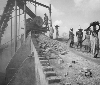
The second category is the mining of relatively high-value minerals, notably gold and precious stones (see figure 2). The output is generally exported, through sales to approved agencies or through smuggling. The size and character of this type of small-scale mining have made what laws there are inadequate and impossible to apply.
Figure 2. Small-scale gold mine in Zimbabwe
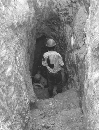
Small-scale mining provides considerable employment, particularly in rural areas. In some countries, many more people are employed in small-scale, often informal, mining than in the formal mining sector. The limited data that exist suggest that upwards of six million people engage in small-scale mining. Unfortunately, however, many of these jobs are precarious and are far from conforming with international and national labour standards. Accident rates in small-scale mines are routinely six of seven times higher than in larger operations, even in industrialized countries. Illnesses, many due to unsanitary conditions are common at many sites. This is not to say that there are no safe, clean, small-scale mines—there are, but they tend to be a small minority.
A special problem is the employment of children. As part of its International Programme for the Elimination of Child Labour, the ILO is undertaking projects in several countries in Africa, Asia and Latin America to provide educational opportunities and alternative income-generating prospects to remove children from coal, gold and gemstone mines in three regions in these countries. This work is being coordinated with the international mineworkers union (ICEM) and with local non-governmental organizations (NGOs) and government agencies.
NGOs have also worked hard and effectively at the local level to introduce appropriate technologies to improve efficiency and mitigate the health and environmental impact of small-scale mining. Some international governmental organizations (IGOs) have undertaken studies and developed guidelines and programmes of action. These address child labour, the role of women and indigenous people, taxation and land title reform, and environmental impact but, so far, they appear to have had little discernible effect. It should be noted, however, that without the active support and participation of governments, the success of such efforts is problematic.
Also, for the most part, there seems to be little interest among small-scale miners in using cheap, readily-available and effective technology to mitigate health and environmental effects, such as retorts to recapture mercury. There is often no incentive to do so, since the cost of mercury is not a constraint. Moreover, particularly in the case of itinerant miners, there is frequently no long-term interest in preserving the land for use after the mining has ceased. The challenge is to show small-scale miners that there are better ways to go about their mining that would not unduly constrain their activities and be better for them in terms of health and wealth, better for the land and better for the country. The “Harare Guidelines”, developed at the 1993 United Nations Interregional Seminar on Guidelines for the Development of Small/Medium Scale Mining, provide guidance for governments and for development agencies in tackling the different issues in a complete and coordinated way. The absence of involvement by employers’ and workers’ organizations in most small-scale mining activity puts a special responsibility on the government in bringing small-scale mining into the formal sector, an action that would improve the lot of small-scale miners and markedly increase the economic and social benefits of small-scale mining. Also, at an international roundtable in 1995 organized by the World Bank, a strategy for artisanal mining that aims to minimize negative side effects—including poor safety and health conditions of this activity—and maximize the socio-economic benefits was developed.
The Safety and Health in Mines Convention and its accompanying Recommendation (No. 183) set out in detail an internationally agreed benchmark to guide national law and practice. It covers all mines, providing a floor—the minimum safety requirement against which all changes in mine operations should be measured. The provisions of the Convention are already being included in new mining legislation and in collective agreements in several countries and the minimum standards it sets are exceeded by the safety and health regulations already promulgated in many mining countries. It remains for the Convention to be ratified in all countries (ratification would give it the force of law), to ensure that the appropriate authorities are properly staffed and funded so that they can monitor the implementation of the regulations in all sectors of the mining industry. The ILO will also monitor the application of the Convention in countries that ratify it.
Environmental and Public Health Issues
Adapted from UNEP and IISI 1997 and an unpublished article by Jerry Spiegel.
Because of the sheer volume and complexity of its operations and its extensive use of energy and raw materials, the iron and steel industry, like other “heavy” industries, has the potential of having a significant impact on the environment and the population of nearby communities. Figure 1 summarizes the pollutants and wastes generated by its major production processes. They comprise three primary categories: air pollutants, waste water contaminants and solid wastes.
Figure 1. Flow chart of pollutants & wastes generated by different processes
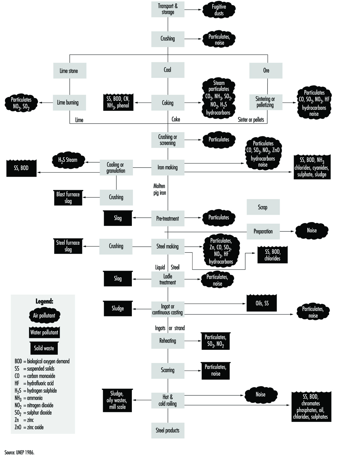
Historically, investigations of the public health impact of the iron and steel industry have concentrated on the localized effects in the densely populated local areas in which steel production has been concentrated and particularly in specific regions where acute air pollution episodes have been experienced, such as the Donora and Meuse valleys, and the triangle between Poland, the former Czechoslovakia and the former German Democratic Republic (WHO 1992).
Air Pollutants
Air pollutants from iron- and steel-making operations have historically been an environmental concern. These pollutants include gaseous substances such as oxides of sulphur, nitrogen dioxide and carbon monoxide. In addition, particulates such as soot and dust, which may contain iron oxides, have been the focus of controls. Emissions from coke ovens and from coke oven by-product plants have been a concern, but the continuous improvements in the technology of steel-making and of emissions control during the past two decades, coupled with more stringent government regulations, have significantly reduced such emissions in North America, Western Europe and Japan. Total pollution control costs, over half of which relate to air emissions, have been estimated to range from 1 to 3% of total production costs; air- pollution control installations have represented approximately 10 to 20% of total plant investments. Such costs create a barrier to the global application of state-of-the-art controls in developing countries and for older, economically marginal enterprises.
Air pollutants vary with the particular process, the engineering and construction of the plant, the raw materials employed, the sources and amounts of the energy required, the extent to which waste products are recycled into the process and the efficiency of the pollution controls. For example, the introduction of basic-oxygen steel making has permitted the collection and recycling of waste gases in a controlled manner, reducing the amounts to be exhausted, while the use of the continuous-casting process has reduced the consumption of energy, resulting in a reduction of emissions. This has increased product yield and improved quality.
Sulphur dioxide
The amount of sulphur dioxide, formed largely in the combustion processes, depends primarily on the sulphur content of the fossil fuel employed. Both coke and coke-oven gas used as fuels are major sources of sulphur dioxide. In the atmosphere, sulphur dioxide may react with oxygen radicals and water to form a sulphuric acid aerosol and, in combination with ammonia, may form an ammonium sulphate aerosol. The health effects attributed to sulphur oxides are not only due to the sulphur dioxide but also to its tendency to form such respirable aerosols. In addition, sulphur dioxide may be adsorbed onto particulates, many of which are in the respirable range. Such potential exposures may be reduced not only by use of fuels with low sulphur content but also by reduction of the concentration of the particulates. The increased use of electric furnaces has decreased the emission of sulphur oxides by eliminating the need for coke, but this has passed on this pollution control burden to the plants generating electricity. Desulphurization of coke-oven gas is achieved by the removal of reduced sulphur compounds, primarily hydrogen sulphide, prior to combustion.
Nitrogen oxides
Like the sulphur oxides, oxides of nitrogen, primarily nitrogen oxide and nitrogen dioxide, are formed in fuel combustion processes. They react with oxygen and volatile organic compounds (VOCs) in the presence of ultraviolet (UV) radiation to form ozone. They also combine with water to form nitric acid, which, in turn, combines with ammonia to form ammonium nitrate. These may also form respirable aerosols which can be removed from the atmosphere through wet or dry deposition.
Particulate matter
Particulate matter, the most visible form of pollution, is a varying, complex mixture of organic and inorganic materials. Dust may be blown from stockpiles of iron ore, coal, coke and limestone or it may enter the air during their loading and transport. Coarse materials generate dust when they are rubbed together or crushed under vehicles. Fine particles are generated in the sintering, smelting and melting processes, particularly when molten iron comes in contact with air to form iron oxide. Coke ovens produce fine coal coke and tar emissions. Potential health effects depend on the number of particles in the respirable range, the chemical composition of the dust and the duration and concentration of exposure.
Sharp reductions in the levels of particulate pollution have been achieved. For example, by using electrostatic precipitators to clean dry waste gases in oxygen steel making, one German steel works decreased the level of emitted dust from 9.3 kg/t of crude steel in 1960 to 5.3 kg/t in 1975 and to somewhat less than 1 kg/t by 1990. The cost, however, was a marked rise in energy consumption. Other methods of particulate pollution control include the use of wet scrubbers, bag houses and cyclones (which are effective only against large particles).
Heavy metals
Metals such as cadmium, lead, zinc, mercury, manganese, nickel and chromium can be emitted from a furnace as a dust, fume or vapour or they may be adsorbed by particulates. Health effects, which are described elsewhere in this Encyclopaedia, depend on the level and duration of exposure.
Organic emissions
Organic emissions from primary steel operations may include benzene, toluene, xylene, solvents, PAHs, dioxins and phenols. The scrap steel used as raw material may include a variety of these substances, depending on its source and the way it was used (e.g., paint and other coatings, other metals and lubricants). Not all of these organic pollutants are captured by the conventional gas cleaning systems.
Radioactivity
In recent years, there have been reports of instances in which radioactive materials have inadvertently been included in the scrap steel. The physicochemical properties of the nuclides (e.g., melting and boiling temperatures and affinity for oxygen) will determine what happens to them in the steel making process. There may be an amount sufficient to contaminate the steel products, the by-products and the various types of wastes and thus require a costly clean-up and disposal. There is also the potential contamination of the steel-making equipment, with resultant potential exposure of the steel workers. However, many steel operations have installed sensitive radiation detectors to screen all purchased steel scrap.
Carbon dioxide
Although it has no effect on human health or ecosystems at the usual atmospheric levels, carbon dioxide is important because of its contribution to the “greenhouse effect”, which is associated with global warming. The steel industry is a major generator of carbon dioxide, more from the use of carbon as a reducing agent in the production of iron from iron ore than from its use as a source of energy. By 1990, through a variety of measures for blast furnace coke rate reduction, waste-heat recovery and energy saving, carbon dioxide emissions by the iron and steel industry had been reduced to 47% of the levels in 1960.
Ozone
Ozone, a major constituent of atmospheric smog near the surface of the earth, is a secondary pollutant formed in air by the photochemical reaction of sunlight on nitrogen oxides, facilitated to a varying degree, depending on their structure and reactivity, by a range of VOCs. The major source of ozone precursors is motor vehicle exhausts, but some are also generated by iron and steel plants as well as by other industries. As a result of atmospheric and topographic conditions, the ozone reaction may take place at great distances from their source.
Waste Water Contaminants
Steel works discharge large volumes of water to lakes, rivers and streams, with additional volumes being vaporized while cooling coke or steel. Waste water retained in unsealed or leaking holding ponds can seep through and may contaminate the local water table and underground streams. These may also be contaminated by the leaching of rainwater through piles of raw materials or accumulations of solid wastes. Contaminants include suspended solids, heavy metals and oils and greases. Temperature changes in natural waters due to discharge of higher temperature process water (70% of steel-making process water is used for cooling) may affect the ecosystems of these waters. Consequently, cooling treatment prior to discharge is essential and can be achieved through application of available technology.
Suspended solids
Suspended solids (SS) are the main waterborne pollutants discharged during steel production. They comprise mainly iron oxides from scale formation during processing; coal, biological sludge, metallic hydroxides and other solids may also be present. These are largely non-toxic in aqueous environments at normal discharge levels. Their presence at higher levels may lead to discolouration of streams, de-oxygenation and silting.
Heavy metals
Steel-making process water may contain high levels of zinc and manganese, while discharges from cold-rolling and coatings areas may contain zinc, cadmium, aluminium, copper and chromium. These metals are naturally present in the aquatic environment; it is their presence at higher than usual concentrations that creates concern about potential effects on humans and the ecosystems. These concerns are increased by the fact that, unlike many organic pollutants, these heavy metals do not biodegrade to harmless end products and may become concentrated in sediments and in the tissues of fish and other aquatic life. Further, by being combined with other contaminants (e.g., ammonia, organic compounds, oils, cyanides, alkalis, solvents and acids), their potential toxicity may be increased.
Oils and greases
Oils and greases may be present in waste water in both soluble and insoluble forms. Most heavy oils and greases are insoluble and are relatively easily removed. They may become emulsified, however, by contact with detergents or alkalis or by being agitated. Emulsified oils are routinely used as part of the process in cold mills. Except for causing discolouration of the water surface, small quantities of most aliphatic oil compounds are innocuous. Monohydric aromatic oil compounds, however, may be toxic. Further, oil components may contain such toxicants as PCBs, lead and other heavy metals. In addition to the question of toxicity, the biological and chemical oxygen demand (BOD and COD) of oils and other organic compounds can decrease the oxygen content of the water, thus affecting the viability of aquatic life.
Solid Wastes
Much of the solid waste produced in steel making is reusable. The process of producing coke, for example, gives rise to coal derivatives which are important raw materials for the chemical industry. Many by-products (e.g., coke dust) can be fed back into the production processes. Slag produced when the impurities present in coal and iron ore melt and combine with the lime used as a flux in smelting can be used in a number of ways: land fill for reclamation projects, in road building and as raw material for sintering plants that supply blast furnaces. Steel, regardless of grade, size, use or length of time in service, is completely recyclable and can be recycled repeatedly without any degradation of its mechanical, physical or metallurgical properties. The recycling rate is estimated to be 90%. Table 1presents an overview of the degree to which the Japanese steel making industry has achieved the recycling of waste materials.
Table 1. Waste generated and recycled in steel production in Japan
|
Generation (A) |
Landfill (B) |
Re-use |
|
|
Slag Blast furnaces |
24,717 |
712 |
97.1 |
|
Dust |
4,763 |
238 |
95.0 |
|
Sludge |
519 |
204 |
60.7 |
|
Waste oil |
81 |
||
|
Total |
41,519 |
3,570 |
91.4 |
Source: IISI 1992.
Energy Conservation
Energy conservation is desirable not only for economic reasons but also for reducing pollution at energy-supply facilities such as electric utilities. The amount of energy consumed in steel production varies widely with the processes used and the mix of scrap metal and iron ore in the feed material. The energy intensity of United States scrap-based plants in 1988 averaged 21.1 gigajoules per tonne while the Japanese plants consumed about 25% less. A model International Iron and Steel Institute (IISI) scrap-based plant required only 10.1 gigajoules per tonne (IISI 1992).
Increases in the cost of energy have stimulated development of energy- and materials-saving technologies. Low-energy gases, such as by-product gases produced in the blast-furnace and coke-oven processes, are recovered, cleaned and used as a fuel. Consumption of coke and auxiliary fuel by the German steel industry, which averaged 830 kg/tonne in 1960, was reduced to 510 kg/tonne in 1990. The Japanese steel industry was able to reduce its share of total Japanese energy consumption from 20.5% in 1973 to about 7% in 1988. The United States steel industry has made major investments in energy conservation. The average mill has reduced energy consumption by 45% since 1975 through process modification, new technology and restructuring (carbon dioxide emissions have fallen proportionately).
Facing the Future
Traditionally, governments, trade associations and individual industries have approached environmental concerns on a media-specific basis, dealing separately, for example, with air, water and waste disposal problems. While useful, this has sometimes merely shifted the problem from one environmental area to another, as in the case of costly waste water treatment which leaves the subsequent problem of disposing of the treatment sludge, which can also cause serious ground water pollution.
In recent years, however, the international steel industry has addressed this problem through Integrated Pollution Control, which has further developed into Total Environmental Risk Management, a programme that looks at all impacts simultaneously and addresses the priority areas systematically. A second development of equal importance has been a focus on preventive rather than remedial action. This addresses such issues as plant siting, site preparation, plant layout and equipment, specification of day-to-day management responsibilities, and the assurance of adequate staff and resources to monitor compliance with environmental regulations and report the results to appropriate authorities.
The Industry and Environment Centre, established in 1975 by the United Nations Environment Programme (UNEP), aims to encourage cooperation between the industries and governments in order to promote environmentally sound industrial development. Its goals include:
- encouragement of the incorporation of environmental criteria in industrial development plans
- facilitation of the implementation of procedures and principles for the protection of the environment
- promotion of the use of safe and clean techniques
- stimulation of the exchange of information and experience throughout the world.
The UNEP works closely with the IISI, the first international industry association devoted to a single industry. The IISI’s members include publicly- and privately-owned steel-producing companies and national and regional steel industry associations, federations and research institutes in the 51 countries which, together, account for over 70% of the total world steel production. IISI, often in concert with UNEP, produces statements of environmental policy and principles and technical reports such as the one on which much of this article has been based (UNEP and IISI 1997). Together, they are working to address the economic, social, moral, personal, management and technological factors that influence compliance with environmental principles, policies and regulations.
Health and Safety Problems and Patterns
Adapted in part from an unpublished article by Simon Pickvance.
The iron and steel industry is a “heavy industry”: in addition to the safety hazards inherent in giant plants, massive equipment and movement of large masses of materials, workers are exposed to the heat of molten metal and slag at temperatures up to 1,800°C, toxic or corrosive substances, respirable air-borne contaminants and noise. Spurred by trade unions, economic pressures for greater efficiency and governmental regulations, the industry has made great strides in the introduction of newer equipment and improved processes which afford greater safety and better control of physical and chemical hazards. Workplace fatalities and lost-time accidents have been significantly reduced, but are still a significant problem (ILO 1992). Steel making remains a dangerous trade in which the potential hazards cannot always be designed out. Accordingly, this presents a formidable challenge to everyday plant management. It calls for ongoing research, continuous monitoring, responsible supervision and updated education and training of workers on all levels.
Physical Hazards
Ergonomic problems
Musculoskeletal injuries are common in steel making. Despite the introduction of mechanization and assistive devices, manual handling of large, bulky and/or heavy objects remains a frequent necessity. Constant attention to housekeeping is necessary to reduce the number of slips and falls. Furnace bricklayers have been shown to be at highest risk of work-related upper arm and low back problems. The introduction of ergonomics into the design of equipment and controls (e.g., crane drivers’ cabs) based on study of the physical and mental requirements of the job, coupled with such innovations as job rotation and team working, are recent developments aimed at enhancing the safety, well-being and performance of steel workers.
Noise
Steel making is one of the noisiest industries, although hearing conservation programs are decreasing the risk of hearing loss. The major sources include fume extraction systems, vacuum systems using steam ejectors, electrical transformers and the arc process in electrical arc furnaces, rolling mills and the large fans used for ventilation. At least half of noise-exposed workers will be handicapped by noise-induced hearing loss after as little as 10 or 15 years on the job. Hearing conservation programmes, described in detail elsewhere in this Encyclopaedia, include periodic noise and hearing assessments, noise control engineering and maintenance of machines and equipment, personal protection, and worker education and training
Causes of hearing loss other than noise include burns to the eardrum from particles of slag, scale or molten metal, perforation of the drum from intense impulse noise and trauma from falling or moving objects. A survey of compensation claims filed by Canadian steelworkers revealed that half of those with occupational hearing loss also had tinnitus (McShane, Hyde and Alberti 1988).
Vibration
Potentially hazardous vibration is created by oscillating mechanical movements, most often when machine movements have not been balanced, when operating shop floor machines and when using such portable tools as pneumatic drills and hammers, saws and grindstones. Damage to vertebral discs, low back pain and degeneration of the spine have been attributed to whole body vibration in a number of studies of overhead crane operators (Pauline et al. 1988).
Whole body vibration can cause a variety of symptoms (e.g., motion sickness, blurring and loss of visual acuity) which may lead to accidents. Hand-arm vibration has been associated with carpal tunnel syndrome, degenerative joint changes and Reynaud’s phenomenon in the finger tips (“white finger disease”), which may cause permanent disability. A study of chippers and grinders showed that they were more than twice as likely to develop Dupuytren’s contracture than a comparison group of workers (Thomas and Clarke 1992).
Heat exposure
Heat exposure is a problem throughout the iron and steel industry, especially in plants located in hot climates. Recent research has shown that, contrary to previous belief, the highest exposures occur during forging, when workers are monitoring hot steel continuously, rather than during melting, when, although temperatures are higher, they are intermittent and their effects are limited by the intense heating of the exposed skin and by the use of eye protection (Lydahl and Philipson 1984). The danger of heat stress is reduced by adequate fluid intake, adequate ventilation, the use of heat shields and protective clothing, and periodic breaks for rest or work at a cooler task.
Lasers
Lasers have a wide range of applications in steel making and may cause retinal damage at power levels far below those required to have effects on the skin. Laser operators can be protected by sharp focus of the beam and the use of protective goggles, but other workers may be injured when they unknowingly step into the beam or when it is inadvertently reflected at them.
Radioactive nuclides
Radioactive nuclides are employed in many measuring devices. Exposures can usually be controlled by posting of warning signs and appropriate shielding. Much more dangerous, however, is the accidental or careless inclusion of radioactive materials in the scrap steel being recycled. To prevent this, many plants are using sensitive radiation detectors to monitor all scrap before it is introduced into the processing.
Airborne Pollutants
Steel workers may be exposed to a wide range of pollutants depending on the particular process, the materials involved and the effectiveness of monitoring and control measures. Adverse effects are determined by the physical state and propensities of the pollutant involved, the intensity and duration of the exposure, the extent of accumulation in the body and the sensitivity of the individual to its effects. Some effects are immediate while others may take years and even decades to develop. Changes in processes and equipment, along with improvement of measures to keep exposures below toxic levels, have reduced the risks to the workers. However, these have also introduced new combinations of pollutants and there is always the danger of accidents, fires and explosions.
Dust and fumes
Emissions of fumes and particulates are a major potential problem for employees working with molten metals, making and handling coke, and charging and tapping furnaces. They are also troublesome to workers assigned to equipment maintenance, duct cleaning and refractory wrecking operations. Health effects are related to the size of the particles (i.e., the proportion that are respirable) and the metals and aerosols that may be adsorbed on their surfaces. There is evidence that exposure to irritant dust and fumes may also make steelworkers more susceptible to reversible narrowing of the airways (asthma) which, over time, may become permanent (Johnson et al. 1985).
Silica
Exposures to silica, with resultant silicosis, once quite common among workers in such jobs as furnace maintenance in melting shops and blast furnaces, have been lowered through the use of other materials for furnace linings as well as automation, which has reduced the number of workers in these processes.
Asbestos
Asbestos, once used extensively for thermal and noise insulation, is now encountered only in maintenance and construction activities when formerly installed asbestos materials are disturbed and generate airborne fibres. The long term effects of asbestos exposure, described in detail in other sections of this Encyclopaedia, include asbestosis, mesothelioma and other cancers. A recent cross-sectional study found pleural pathology in 20 out of 900 steelworkers (2%), much of which was diagnosed as restrictive lung disease characteristic of asbestosis (Kronenberg et al. 1991).
Heavy metals
Emissions generated in steel making may contain heavy metals (e.g., lead, chromium, zinc, nickel and manganese) in the form of fumes, particulates, and adsorbates on inert dust particles. They are often present in scrap steel streams and are also introduced in the manufacture of special types of steel products. Research carried out on workers melting manganese alloys has shown impaired physical and mental performance and other symptoms of manganism at exposure levels significantly below the limits currently allowable in most countries (Wennberg et al. 1991). Short-term exposure to high levels of zinc and other vaporized metals may cause “metal fume fever”, which is characterized by fever, chills, nausea, respiratory difficulty and fatigue. Details of the other toxic effects produced by heavy metals are found elsewhere in this Encyclopaedia.
Acid mists
Acid mists from pickling areas can cause skin, eye and respiratory irritation. Exposure to hydrochloric and sulphuric acid mists from pickling baths have also been associated in one study with a nearly twofold increase in laryngeal cancer (Steenland et al. 1988).
Sulphur compounds
The predominant source of sulphur emissions in steel making is the use of high-sulphur fossil fuels and blast furnace slag. Hydrogen sulphide has a characteristic unpleasant odour and short-term effects of relatively low-level exposures include dryness and irritation of nasal passages and the upper respiratory tract, coughing, shortness of breath and pneumonia. Longer exposures to low levels may cause eye irritation, while permanent eye damage may be produced by higher levels of exposure. At higher levels, there may also be a temporary loss of smell which can delude workers into believing that they are no longer being exposed.
Oil mists
Oil mists generated in the cold rolling of steel can produce irritation of skin, mucous membranes and upper respiratory tract, nausea, vomiting and headache. One study reported cases of lipoid pneumonia in rolling mill workers who had longer exposures (Cullen et al. 1981).
Polycyclic aromatic hydrocarbons
PAHs are produced in most combustion processes; in steelworks, coke making is the major source. When coal is partially burnt to produce coke, a large number of volatile compounds are distilled off as coal tar pitch volatiles, including PAHs. These may be present as vapours, aerosols or adsorbates on fine particulates. Short-term exposures may cause irritation of the skin and mucous membranes, dizziness, headache and nausea, while long-term exposure has been associated with carcinogenesis. Studies have shown that coke-oven workers have a lung cancer mortality rate twice that of the general population. Those most exposed to coal tar pitch volatiles are at the highest risk. These included workers on the oven topside and workers with the longest period of exposure (IARC 1984; Constantino, Redmond and Bearden 1995). Engineering controls have reduced the numbers of workers at risk in some countries.
Other chemicals
Over 1,000 chemicals are used or encountered in steel making: as raw materials or as contaminants in scrap and/or in fuels; as additives in special processes; as refractories; and as hydraulic fluids and solvents used in plant operation and maintenance. Coke making produces by-products such as tar, benzene and ammonia; others are generated in the different steel-making processes. All may potentially be toxic, depending on the nature of the chemicals, the type, the level and duration of the exposures, their reactivity with other chemicals and the susceptibility of the exposed worker. Accidental heavy exposures to fumes containing sulphur dioxide and nitrogen oxides have caused cases of chemical pneumonitis. Vanadium and other alloy additions may cause chemical pneumonitis. Carbon monoxide, which is released in all combustion processes, can be hazardous when maintenance of equipment and its controls are substandard. Benzene, along with toluene and xylene, is present in coke-oven gas and causes respiratory and central nervous system symptoms on acute exposure; long-term exposures may lead to bone marrow damage, aplastic anaemia and leukaemia.
Stress
High levels of work stress are found in the steel industry. Exposures to radiant heat and noise are compounded by the need for constant vigilance to avoid accidents and potentially hazardous exposures. Since many processes are in continuous operation, shift work is a necessity; its impact on well-being and on workers’ essential social support are detailed elsewhere in this Encyclopaedia. Finally, there is the potent stressor of potential job loss resulting from automation and changes in processes, plant relocation and downsizing of the workforce.
Preventive Programmes
Protecting steel workers against potential toxicity requires allocation of adequate resources for a continuing, comprehensive and coordinated programme that should include the following elements:
- assessment of all raw materials and fuels and, when possible, substitution of safer products for those known to be hazardous
- effective controls for the storage and safe handling of raw materials, products, by-products and wastes
- continuous monitoring of workers’ personal occupational environment and ambient air quality, with biological monitoring when required, and periodic medical surveillance of workers to detect more subtle health effects and verify fitness for their jobs
- engineering systems to control potential exposures (e.g., equipment enclosures and adequate exhaust and ventilation systems) supplemented by personal protective equipment (e.g., shields, gloves, safety glasses and goggles, hearing protectors, respirators, foot and body protection, etc.) when engineering controls do not suffice
- application of ergonomic principles to design of equipment, machine controls and tools and analysis of job structure and content as a guide to interventions that may prevent injury and enhance workers’ well-being
- maintenance of readily available, up-to-date information about potential hazards, which must be disseminated among workers and supervisors as part of an ongoing worker education and training programme
- installation and maintenance of systems for the storage and retrieval of the voluminous health and safety data, as well as for the analysis and reporting of records of inspection findings, accidents and worker injury and disease.
" DISCLAIMER: The ILO does not take responsibility for content presented on this web portal that is presented in any language other than English, which is the language used for the initial production and peer-review of original content. Certain statistics have not been updated since the production of the 4th edition of the Encyclopaedia (1998)."