Children categories

56. Accident Prevention (13)

56. Accident Prevention
Chapter Editor: Jorma Saari
Table of Contents
Tables and Figures
Introduction
Jorma Saari
Concepts of Accident Analysis
Kirsten Jorgensen
Theory of Accident Causes
Abdul Raouf
Human Factors in Accident Modelling
Anne-Marie Feyer and Ann M. Williamson
Accident Models: Risk Homeostasis
Gerald J.S. Wilde
Accident Modelling
Andrew R. Hale
Accident Sequence Models
Ragnar Andersson
Accident Deviation Models
Urban Kjellén
MAIM: The Merseyside Accident Information Model
Harry S. Shannon and John Davies
Principles of Prevention: The Public Health Approach to Reducing Injuries in the Workplace
Gordon S. Smith and Mark A. Veazie
Theoretical Principles of Job Safety
Reinald Skiba
Principles of Prevention: Safety Information
Mark R. Lehto and James M. Miller
Work-Related Accident Costs
Diego Andreoni
Tables
Click a link below to view table in article context.
1. Taxonomies for the classification of deviations
2. The Haddon Matrix applied to motor vehicle injuries
3. Haddon’s Ten Countermeasure Strategies for construction
4. Safety information mapped to the accident sequence
5. Recommendations within selected warning systems
Figures
Point to a thumbnail to see figure caption, click to see figure in article context.

57. Audits, Inspections and Investigations (7)

57. Audits, Inspections and Investigations
Chapter Editor: Jorma Saari
Table of Contents
Tables and Figures
Safety Audits and Management Audits
Johan Van de Kerckhove
Hazard Analysis: The Accident Causation Model
Jop Groeneweg
Hardware Hazards
Carsten D. Groenberg
Hazard Analysis: Organizational Factors
Urban Kjellén
Workplace Inspection and Regulatory Enforcement
Anthony Linehan
Analysis and Reporting: Accident Investigation
Michel Monteau
Reporting and Compiling Accident Statistics
Kirsten Jorgensen
Tables
Click a link below to view table in article context.
1. Strata in quality & safety policy
2. PAS safety audit elements
3. Assessment of behaviour-control methods
4. General failure types & definitions
5. Concepts of the accident phenomenon
6. Variables characterizing an accident
Figures
Point to a thumbnail to see figure caption, click to see figure in article context.

58. Safety Applications (17)

58. Safety Applications
Chapter Editors: Kenneth Gerecke and Charles T. Pope
Table of Contents
Tables and Figures
Systems Analysis
Manh Trung Ho
Hand and Portable Power Tool Safety
US Department of Labor—Occupational Safety and Health Administration; edited by Kenneth Gerecke
Moving Parts of Machines
Tomas Backström and Marianne Döös
Machine Safeguarding
US Department of Labor— Occupational Safety and Health Administration; edited by Kenneth Gerecke
Presence Detectors
Paul Schreiber
Devices for Controlling, Isolating and Switching Energy
René Troxler
Safety-Related Applications
Dietmar Reinert and Karlheinz Meffert
Software and Computers: Hybrid Automated Systems
Waldemar Karwowski and Jozef Zurada
Principles for the Design of Safe Control Systems
Georg Vondracek
Safety Principles for CNC Machine Tools
Toni Retsch, Guido Schmitter and Albert Marty
Safety Principles for Industrial Robots
Toni Retsch, Guido Schmitter and Albert Marty
Electrical, Electronic and Programmable Electronic Safety-Related Control Systems
Ron Bell
Technical Requirements for Safety-Related Systems Based on Electrical, Electronic and Programmable Electronic Devices
John Brazendale and Ron Bell
Rollover
Bengt Springfeldt
Falls from Elevations
Jean Arteau
Confined Spaces
Neil McManus
Principles of Prevention: Materials Handling and Internal Traffic
Kari Häkkinen
Tables
Click a link below to view table in article context.
1. Possible dysfunctions of a two-button control circuit
2. Machine guards
3. Devices
4. Feeding & ejection methods
5. Circuit structures’ combinations in machine controls
6. Safety integrity levels for protection systems
7. Software design & development
8. Safety integrity level: type B components
9. Integrity requirements: electronic system architectures
10. Falls from elevations: Quebec 1982-1987
11.Typical fall prevention & fall arrest systems
12. Differences between fall prevention & fall arrest
13. Sample form for assessment of hazardous conditions
14. A sample entry permit
Figures
Point to a thumbnail to see figure caption, click to see figure in article context.

59. Safety Policy and Leadership (7)

59. Safety Policy and Leadership
Chapter Editor: Jorma Saari
Table of Contents
Tables and Figures
Safety Policy, Leadership and Culture
Dan Petersen
Safety Culture and Management
Marcel Simard
Organizational Climate and Safety
Nicole Dedobbeleer and François Béland
Participatory Workplace Improvement Process
Jorma Saari
Methods of Safety Decision Making
Terje Sten
Risk Perception
Bernhard Zimolong and Rüdiger Trimpop
Risk Acceptance
Rüdiger Trimpop and Bernhard Zimolong
Tables
Click a link below to view table in article context.
1. Safety climate measures
2. Tuttava & other programme/techniques differences
3. An example of best work practices
4. Performance targets at a printing ink factory
Figures
Point to a thumbnail to see figure caption, click to see figure in article context.

60. Safety Programs (8)

60. Safety Programs
Chapter Editor: Jorma Saari
Table of Contents
Tables and Figures
Occupational Safety Research: An Overview
Herbert I. Linn and Alfred A. Amendola
Government Services
Anthony Linehan
Safety Services: Consultants
Dan Petersen
Implementation of a Safety Programme
Tom B. Leamon
Successful Safety Programmes
Tom B. Leamon
Safety Incentive Programmes
Gerald J. S. Wilde
Safety Promotion
Thomas W. Planek
Case Study: Occupational Health and Safety Campaigns at the National Level in India
K. C. Gupta
Tables
Click a link below to view table in article context.
1. OBM vs. TQM models of employee motivation
2. Indian factories: employment & injuries
Figures
Point to a thumbnail to see figure caption, click to see figure in article context.
Hazard Analysis: The Accident Causation Model
This article examines the role of human factors in the accident causation process and reviews the various preventive measures (and their effectiveness) by which human error may be controlled, and their application to the accident causation model. Human error is an important contributing cause in at least 90 of all industrial accidents. While purely technical errors and uncontrollable physical circumstances may also contribute to accident causation, human error is the paramount source of failure. The increased sophistication and reliability of machinery means that the proportion of causes of accidents attributed to human error increases as the absolute number of accidents decreases. Human error is also the cause of many of those incidents that, although not resulting in injury or death, nevertheless result in considerable economic damage to a company. As such, it represents a major target for prevention, and it will become increasingly important. For effective safety management systems and risk identification programmes it is important to be able to identify the human component effectively through the use of general failure type analysis.
The Nature of Human Error
Human error can be viewed as the failure to reach a goal in the way that was planned, either from a local or wider perspective, due to unintentional or intentional behaviour. Those planned actions may fail to achieve the desired outcomes for the following four reasons:
1. Unintentional behaviour:
- The actions did not go as planned (slips).
- The action was not executed (lapses).
2. Intentional behaviour:
- The plan itself was inadequate (mistakes).
- There were deviations from the original plan (violations).
Deviations can be divided in three classes: skill-, rule- and knowledge-based errors.
- At the skill-based level, behaviour is guided by pre-programmed action schemes. The tasks are routine and continuous, and feedback is usually lacking.
- At the rule-based level, behaviour is guided by general rules. They are simple and can be applied many times in specific situations. The tasks consist of relatively frequent action sequences that start after a choice is made among rules or procedures. The user has a choice: the rules are not automatically activated, but are actively chosen.
- Knowledge-based behaviour is shown in completely new situations where no rules are available and where creative and analytical thinking is required.
In some situations, the term human limitation would be more appropriate than human error. There also are limits to the ability to foresee the future behaviour of complex systems (Gleick 1987; Casti 1990).
Reason and Embrey’s model, the Generic Error Modelling System (GEMS) (Reason 1990), takes into account the error-correcting mechanisms on the skill-, rule- and knowledge-based levels. A basic assumption of GEMS is that day-to-day behaviour implies routine behaviour. Routine behaviour is checked regularly, but between these feedback loops, behaviour is completely automatic. Since the behaviour is skill-based, the errors are slips. When the feedback shows a deviation from the desired goal, rule-based correction is applied. The problem is diagnosed on the basis of available symptoms, and a correction rule is automatically applied when the situation is diagnosed. When the wrong rule is applied there is a mistake.
When the situation is completely unknown, knowledge-based rules are applied. The symptoms are examined in the light of knowledge about the system and its components. This analysis can lead to a possible solution the implementation of which constitutes a case of knowledge-based behaviour. (It is also possible that the problem cannot be solved in a given way and that further knowledge-based rules have to be applied.) All errors on this level are mistakes. Violations are committed when a certain rule is applied that is known to be inappropriate: the thinking of the worker may be that application of an alternative rule will be less time-consuming or is possibly more suitable for the present, probably exceptional, situation. The more malevolent class of violations involves sabotage, a subject that is not within the scope of this article. When organizations are attempting to eliminate human error, they should take into account whether the errors are on the skill-, rule- or knowledge-based level, as each level requires its own techniques (Groeneweg 1996).
Influencing Human Behaviour: An Overview
A comment often made with regard to a particular accident is, “Maybe the person did not realize it at the time, but if he or she had not acted in a certain way, the accident would not have happened.” Much of accident prevention is aimed at influencing the crucial bit of human behaviour alluded to in this remark. In many safety management systems, the solutions and policies suggested are aimed at directly influencing human behaviour. However, it is very uncommon that organizations assess how effective such methods really are. Psychologists have devoted much thought to how human behaviour can best be influenced. In this respect, the following six ways of exercising control over human error will be set forth, and an evaluation will be performed of the relative effectiveness of these methods in controlling human behaviour on a long-term basis (Wagenaar 1992). (See table 1.)
Table 1. Six ways to induce safe behaviour and assessment of their cost-effectiveness
|
No. |
Way of influencing |
Cost |
Long-term effect |
Assessment |
|
1 |
Don’t induce safe behaviour, |
High |
Low |
Poor |
|
2 |
Tell those involved what to do. |
Low |
Low |
Medium |
|
3 |
Reward and punish. |
Medium |
Medium |
Medium |
|
4 |
Increase motivation and awareness. |
Medium |
Low |
Poor |
|
5 |
Select trained personnel. |
High |
Medium |
Medium |
|
6 |
Change the environment. |
High |
High |
Good |
Do not attempt to induce safe behaviour, but make the system “foolproof”
The first option is to do nothing to influence the behaviour of people but to design the workplace in such a way that whatever the employee does, it will not result in any kind of undesirable outcome. It must be acknowledged that, thanks to the influence of robotics and ergonomics, designers have considerably improved on the user-friendliness of workplace equipment. However, it is almost impossible to anticipate all the different kinds of behaviour that people may evince. Besides, workers often regard so-called foolproof designs as a challenge to “beat the system”. Finally, as designers are human themselves, even very carefully foolproof-designed equipment can have flaws (e.g., Petroski 1992). The additional benefit of this approach relative to existing hazard levels is marginal, and in any event initial design and installation costs may increase exponentially.
Tell those involved what to do
Another option is to instruct all workers about every single activity in order to bring their behaviour fully under the control of management. This will require an extensive and not very practical task inventory and instruction control system. As all behaviour is de-automated it will to a large extent eliminate slips and lapses until the instructions become part of the routine and the effect fades away.
It does not help very much to tell people that what they do is dangerous - most people know that very well - because they will make their own choices concerning risk regardless of attempts to persuade them otherwise. Their motivation to do so will be to make their work easier, to save time, to challenge authority and perhaps to enhance their own career prospects or claim some financial reward. Instructing people is relatively cheap, and most organizations have instruction sessions before the start of a job. But beyond such an instruction system the effectiveness of this approach is assessed to be low.
Reward and punish
Although reward and punishment schedules are powerful and very popular means for controlling human behaviour, they are not without problems. Reward works best only if the recipient perceives the reward to be of value at the time of receipt. Punishing behaviour that is beyond an employee’s control (a slip) will not be effective. For example, it is more cost-effective to improve traffic safety by changing the conditions underlying traffic behaviour than by public campaigns or punishment and reward programmes. Even an increase in the chances of being “caught” will not necessarily change a person’s behaviour, as the opportunities for violating a rule are still there, as is the challenge of successful violation. If the situations in which people work invite this kind of violation, people will automatically choose the undesired behaviour no matter how they are punished or rewarded. The effectiveness of this approach is rated as of medium quality, as it usually is of short-term effectiveness.
Increase motivation and awareness
Sometimes it is believed that people cause accidents because they lack motivation or are unaware of danger. This assumption is false, as studies have shown (e.g., Wagenaar and Groeneweg 1987). Furthermore, even if workers are capable of judging danger accurately, they do not necessarily act accordingly (Kruysse 1993). Accidents happen even to people with the best motivation and the highest degree of safety awareness. There are effective methods for improving motivation and awareness which are discussed below under “Change the environment”. This option is a delicate one: in contrast with the difficulty to further motivate people it is almost too easy to de-motivate employees to the extent that even sabotage is considered.
The effects of motivation enhancement programmes are positive only when coupled with behaviour modification techniques such as employee involvement.
Select trained personnel
The first reaction to an accident is often that those involved must have been incompetent. With hindsight, the accident scenarios appear straightforward and easily preventable to someone sufficiently intelligent and properly trained, but this appearance is a deceptive one: in actual fact the employees involved could not possibly have foreseen the accident. Therefore, better training and selection will not have the desirable effect. A base level of training is however a prerequisite for safe operations. The tendency in some industries to replace experienced personnel with inexperienced and inadequately trained people is to be discouraged, as increasingly complex situations call for rule- and knowledge-based thinking that requires a level of experience that such lower-cost personnel often do not possess.
A negative side-effect of instructing people very well and selecting only the highest-classified people is that behaviour can become automatic and slips occur. Selection is expensive, while the effect is not more than medium.
Change the environment
Most behaviour occurs as a reaction to factors in the working environment: work schedules, plans, and management expectations and demands. A change in the environment results in different behaviour. Before the working environment can be effectively changed, several problems must be solved. First, the environmental factors that cause the unwanted behaviour must be identified. Second, these factors must be controlled. Third, management must allow discussion about their role in creating the adverse working environment.
It is more practical to influence behaviour through creating the proper working environment. The problems that should be solved before this solution can be put into practice are (1) that it must be known which environmental factors cause the unwanted behaviour, (2) that these factors must be controlled and (3) that previous management decisions must be considered (Wagenaar 1992; Groeneweg 1996). All these conditions can indeed be met, as will be argued in the remainder of this article. The effectiveness of behaviour modification can be high, even though a change of environment may be quite costly.
The Accident Causation Model
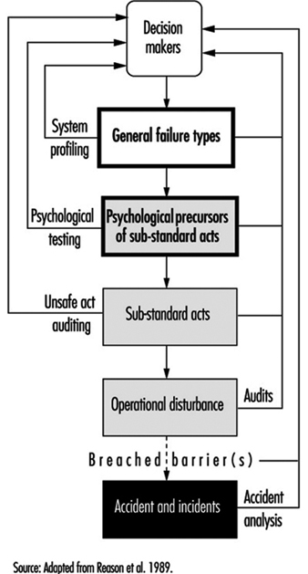
In order to get more insight into the controllable parts of the accident causation process, an understanding of the possible feedback loops in a safety information system is necessary. In figure 1, the complete structure of a safety information system is presented that can form the basis of managerial control of human error. It is an adapted version of the system presented by Reason et al. (1989).
Figure 1. A safety information system
Accident investigation
When accidents are investigated, substantial reports are produced and decision-makers receive information about the human error component of the accident. Fortunately, this is becoming more and more obsolete in many companies. It is more effective to analyse the “operational disturbances” that precede the accidents and incidents. If an accident is described as an operational disturbance followed by its consequences, then sliding from the road is an operational disturbance and getting killed because the driver did not wear a safety belt is an accident. Barriers may have been placed between the operational disturbance and the accident, but they failed or were breached or circumvented.
Unsafe act auditing
A wrong act committed by an employee is called a “substandard act” and not an “unsafe act” in this article: the notion of “unsafe” seems to limit the applicability of the term to safety, whereas it can also be applied, for example, to environmental problems. Substandard acts are sometimes recorded, but detailed information as to which slips, mistakes and violations were performed and why they were performed is hardly ever fed back to higher management levels.
Investigating the employee’s state of mind
Before a substandard act is committed, the person involved was in a certain state of mind. If these psychological precursors, like being in a state of haste or feeling sad, could be adequately controlled, people would not find themselves in a state of mind in which they would commit a substandard act. Since these states of mind cannot be effectively controlled, such precursors are regarded as “black box” material (figure 1).
General failure types
The GFT (general failure type) box in figure 1 represents the generating mechanisms of an accident - the causes of substandard acts and situations. Because these substandard acts cannot be controlled directly, it is necessary to change the working environment. The working environment is determined by 11 such mechanisms (table 2). (In the Netherlands the abbreviation GFT already exists in a completely different context, and has to do with ecologically sound waste disposal, and to avoid confusion another term is used: basic risk factors (BRFs) (Roggeveen 1994).)
Table 2. General failure types and their definitions
|
General failures |
Definitions |
|
1. Design (DE) |
Failures due to poor design of a whole plant as well as individual |
|
2. Hardware (HW) |
Failures due to poor state or unavailability of equipment and tools |
|
3. Procedures (PR) |
Failures due to poor quality of the operating procedures with |
|
4. Error enforcing |
Failures due to poor quality of the working environment, with |
|
5. Housekeeping (HK) |
Failures due to poor housekeeping |
|
6. Training (TR) |
Failures due to inadequate training or insufficient experience |
|
7. Incompatible goals(IG) |
Failures due to the poor way safety and internal welfare are |
|
8. Communication (CO) |
Failures due to poor quality or absence of lines of communication |
|
9. Organization (OR) |
Failures due to the way the project is managed |
|
10. Maintenance |
Failures due to poor quality of the maintenance procedures |
|
11. Defences (DF) |
Failures due to the poor quality of the protection against hazardous |
The GFT box is preceded by a “decision-maker’s” box, as these people determine to a large extent how well a GFT is managed. It is management’s task to control the working environment by managing the 11 GFTs, thereby indirectly controlling the occurrence of human error.
All these GFTs can contribute to accidents in subtle ways by allowing undesirable combinations of situations and actions to come together, by increasing the chance that certain persons will commit substandard acts and by failing to provide the means to interrupt accident sequences already in progress.
There are two GFTs that require some further explanation: maintenance management and defences.
Maintenance management (MM)
Since maintenance management is a combination of factors that can be found in other GFTs, it is not, strictly speaking, a separate GFT: this type of management is not fundamentally different from other management functions. It may be treated as a separate issue because maintenance plays an important role in so many accident scenarios and because most organizations have a separate maintenance function.
Defences (DF)
The category of defences is also not a true GFT, as it is not related to the accident causation process itself. This GFT is related to what happens after an operational disturbance. It does not generate either psychological states of mind or substandard acts by itself. It is a reaction that follows a failure due to the action of one or more GFTs. While it is indeed true that a safety management system should focus on the controllable parts of the accident causation chain before and not after the unwanted incident, nevertheless the notion of defences can be used to describe the perceived effectiveness of safety barriers after a disturbance has occurred and to show how they failed to prevent the actual accident.
Managers need a structure that will enable them to relate identified problems to preventive actions. Measures taken at the levels of safety barriers or substandard acts are still necessary, although these measures can never be completely successful. To trust “last line” barriers is to trust factors that are to a large extent out of management control. Management should not attempt to manage such uncontrollable external devices, but instead must try to make their organizations inherently safer at every level.
Measuring the Level of Control over Human Error
Ascertaining the presence of the GFTs in an organization will enable accident investigators to identify the weak and strong points in the organization. Given such knowledge, one can analyse accidents and eliminate or mitigate their causes and identify the structural weaknesses within a company and fix them before they in fact contribute to an accident.
Accident investigation
The task of an accident analyst is to identify contributing factors and to categorize them. The number of times a contributing factor is identified and categorized in terms of a GFT indicates the extent to which this GFT is present. This is often done by means of a checklist or computer analysis program.
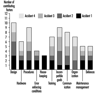
It is possible and desirable to combine profiles from different but similar types of accidents. Conclusions based upon an accumulation of accident investigations in a relatively short time are far more reliable than those drawn from a study in which the accident profile is based upon a single event. An example of such a combined profile is presented in figure 2, which shows data relating to four occurrences of one type of accident.
Figure 2. Profile of an accident type
Some of the GFTs - design, procedures and incompatible goals - score consistently high in all four particular accidents. This means that in each accident, factors have been identified that were related to these GFTs. With respect to the profile of accident 1, design is a problem. Housekeeping, although a major problem area in accident 1, is only a minor problem if more than the first accident is analysed. It is suggested that about ten similar types of accidents be investigated and combined in a profile before far-reaching and possibly expensive corrective measures are taken. This way, the identification of the contributing factors and subsequent categorization of these factors can be done in a very reliable way (Van der Schrier, Groeneweg and van Amerongen 1994).
Identifying the GFTs within an organization pro-actively
It is possible to quantify the presence of GFTs pro-actively, regardless of the occurrence of accidents or incidents. This is done by looking for indicators of the presence of that GFT. The indicator used for this purpose is the answer to a straightforward yes or no question. If answered in the undesired way, it is an indication that something is not functioning properly. An example of an indicator question is: “In the past three months, did you go to a meeting that turned out to be cancelled?” If the employee answers the question in the affirmative, it does not necessarily signify danger, but it is indicative of a deficiency in one of the GFTs—communication. However, if enough questions that test for a given GFT are answered in a way that indicates an undesirable trend, it is a signal to management that it does not have sufficient control of that GFT.
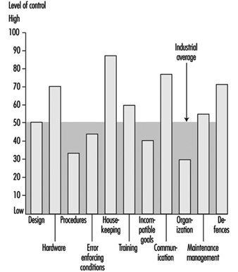
To construct a system safety profile (SSP), 20 questions for each of the 11 GFTs have to be answered. Each GFT is assigned a score ranging from 0 (low level of control) to 100 (high level of control). The score is calculated relative to the industry average in a certain geographical area. An example of this scoring procedure is presented in the box.
The indicators are pseudo-randomly drawn from a database with a few hundred questions. No two subsequent checklists have questions in common, and questions are drawn in such a way that each aspect of the GFT is covered. Failing hardware could, for instance, be the result of either absent equipment or defective equipment. Both aspects should be covered in the checklist. The answering distributions of all questions are known, and checklists are balanced for equal difficulty.
It is possible to compare scores obtained with different checklists, as well as those obtained for different organizations or departments or the same units over a period of time. Extensive validation tests have been done to ensure that all questions in the database have validity and that they are all indicative of the GFT to be measured. Higher scores indicate a higher level of control - that is, more questions have been answered in the “desired” way. A score of 70 indicates that this organization is ranked among the best 30 (i.e., 100 minus 70) of comparable organizations in this kind of industry. Although a score of 100 does not necessarily mean that this organization has total control over a GFT, it does means that with regard to this GFT the organization is the best in the industry.
An example of an SSP is shown in figure 3. The weak areas of Organization 1, as exemplified by the bars in the chart, are procedures, incompatible goals, and error enforcing conditions, as they score below the industry average as shown by the dark grey area. The scores on housekeeping, hardware and defences are very good in Organization 1. On the surface, this well-equipped and tidy organization with all safety devices in place appears to be a safe place to work. Organization 2 scores exactly at the industry average. There are no major deficiencies, and although the scores on hardware, housekeeping and defences are lower, this company manages (on the average) the human error component in accidents better than Organization 1. According to the accident causation model, Organization 2 is safer than Organization 1, although this would not necessarily be apparent in comparing the organizations in “traditional” audits.
Figure 3. Example of a system safety profile
If these organizations had to decide where to allocate their limited resources, the four areas with below average GFTs would have priority. However, one cannot conclude that, since the other GFT scores are so favourable, resources may be safely withdrawn from their upkeep, since these resources are what have most probably kept them at so high a level in the first place.
Conclusions
This article has touched upon the subject of human error and accident prevention. The overview of the literature regarding control of the human error component in accidents yielded a set of six ways by which one can try to influence behaviour. Only one, restructuring the environment or modifying behaviour in order to reduce the number of situations in which people are liable to commit an error, has a reasonably favourable effect in a well-developed industrial organization where many other attempts have already been made. It will take courage on the part of management to recognize that these adverse situations exist and to mobilize the resources that are needed to effect a change in the company. The other five options do not represent helpful alternatives, as they will have little or no effect and will be quite costly.
“Controlling the controllable” is the key principle supporting the approach presented in this article. The GFTs must be discovered, attacked and eliminated. The 11 GFTs are mechanisms that have proven to be part of the accident causation process. Ten of them are aimed at preventing operational disturbances and one (defences) is aimed at the prevention of the operational disturbance’s turning into an accident. Eliminating the impact of the GFTs has a direct bearing upon the abatement of contributing causes of accidents. The questions in the checklists are aimed at measuring the “health state” of a given GFT, from both a general and a safety point of view. Safety is viewed as an integrated part of normal operations: doing the job the way it should be done. This view is in accordance with the recent “quality oriented” management approaches. The availability of policies, procedures and management tools is not the chief concern of safety management: the question is rather whether these methods are actually used, understood and adhered to.
The approach described in this article concentrates upon systemic factors and the way in which management decisions can be translated into unsafe conditions at the workplace, in contrast to the conventional belief that attention should be directed towards the individual workers who perform unsafe acts, their attitudes, motivations and perceptions of risk.
An indication of the level of control your organization has over the GFT “Communication”
In this box a list of 20 questions is presented. The questions in this list have been answered by employees of more than 250 organizations in Western Europe. These organizations were operating in different fields, ranging from chemical companies to refineries and construction companies. Normally, these questions would be tailor-made for each branch. This list serves as an example only to show how the tool works for one of the GFTs. Only those questions have been selected that have proved to be so “general” that they are applicable in at least 80% of the industries.
In “real life” employees would not only have to answer the questions (anonymously), they would also have to motivate their answers. It is not sufficient to answer “Yes” on, for example, the indicator “Did you have to work in the past 4 weeks with an outdated procedure?” The employee would have to indicate which procedure it was and under which conditions it had to be applied. This motivation serves two goals: it increases the reliability of the answers and it provides management with information it can act upon.
Caution is also necessary when interpreting the percentile score: in a real measurement, each organization would be matched against a representative sample of branch-related organizations for each of the 11 GFTs. The distribution of percentiles is from May 1995, and this distribution does change slightly over time.
How to measure the “level of control”
Answer all 20 indicators with your own situation in mind and beware of the time limits in the questions. Some of the questions might not be applicable for your situation; answer them with “n.a.” It might be impossible for you to answer some questions; answer them with a question mark“?”.
After you have answered all questions, compare your answers with the reference answers. You get a point for each “correctly” answered question.
Add the number of points together. Calculate the percentage of correctly answered questions by dividing the number of points by the number of questions you have answered with either “Yes” or “No”. The “n.a.” and “?” answers are not taken into account. The result is a percentage between 0 and 100.
The measurement can be made more reliable by having more people answering the questions and by averaging their scores over the levels or functions in the organization or comparable departments.
Twenty questions about the GFT “Communication”
Possible answers to the questions: Y = Yes; N = No; n.a. = not applicable; ? = don’t know.
- In the past 4 weeks has the telephone directory provided you with incorrect or insufficient information?
- In the past 2 weeks has your telephone conversation been interrupted due to a malfunctioning of the telephone system?
- Have you received mail in the past week that was not relevant to you?
- Has there been an internal or external audit in the past 9 months of your office paper trail?
- Was more than 20% of the information you received in the past 4 weeks labelled “urgent”?
- Did you have to work in the past 4 weeks with a procedure that was difficult to read (e.g., phrasing or language problems)?
- Have you gone to a meeting in the past 4 weeks that turned out not to be held at all?
- Has there been a day in the past 4 weeks that you had five or more meetings?
- Is there a “suggestion box” in your organization?
- Have you been asked to discuss a matter in the past 3 months that later turned out to be already decided upon?
- Have you sent any information in the past 4 weeks that was never received?
- Have you received information in the past 6 months about changes in policies or procedures more than a month after it had been put into effect?
- Have the minutes of the last three safety meetings been sent to your management?
- Has “office” management stayed at least 4 hours at the location when making the last site visit?
- Did you have to work in the past 4 weeks with procedures with conflicting information?
- Have you received within 3 days feedback on requests for information in the past 4 weeks?
- Do people in your organization speak different languages or dialects (different mother tongue)?
- Was more than 80% of the feedback you received (or gave) from management in the past 6 months of a “negative nature”?
- Are there parts of the location/workplace where it is difficult to understand each other due to extreme noise levels?
- In the past 4 weeks, have tools and/or equipment been delivered that not had been ordered?
Reference answers:
1 = N; 2 = N; 3 = N; 4 = Y; 5 = N; 6 = N; 7 = N; 8 = N; 9 = N; 10 = N; 11 = N; 12 = N; 13 = Y; 14 = N; 15 = N; 16 = Y; 17 = N; 18 = N; 19 = Y; 20 = N.
Scoring GFT “Communication”
Percent score = (a/b) x 100
where a = no. of questions answered correctly
where b = no. of questions answered “Y” or “N”.
|
Your score % |
Percentile |
% |
Equal or better |
|
0-10 |
0-1 |
100 |
99 |
|
11-20 |
2-6 |
98 |
94 |
|
21-30 |
7-14 |
93 |
86 |
|
31-40 |
15-22 |
85 |
78 |
|
41-50 |
23-50 |
79 |
50 |
|
51-60 |
51-69 |
49 |
31 |
|
61-70 |
70-85 |
30 |
15 |
|
71-80 |
86-97 |
14 |
3 |
|
81-90 |
98-99 |
2 |
1 |
|
91-100 |
99-100 |
Hardware Hazards
This article addresses “machine” hazards, those which are specific to the appurtenances and hardware used in the industrial processes associated with pressure vessels, processing equipment, powerful machines and other intrinsically risky operations. This article does not address worker hazards, which implicate the actions and behaviour of individuals, such as slipping on working surfaces, falling from elevations and hazards from using ordinary tools. This article focuses on machine hazards, which are characteristic of an industrial job environment. Since these hazards threaten anyone present and may even be a threat to neighbours and the external environment, the analysis methods and the means for prevention and control are similar to the methods used to deal with risks to the environment from industrial activities.
Machine Hazards
Good quality hardware is very reliable, and most failures are caused by secondary effects like fire, corrosion, misuse and so on. Nevertheless, hardware may be highlighted in certain accidents, because a failing hardware component is often the most conspicuous or visibly prominent link of the chain of events. Although the term hardware is used in a broad sense, illustrative examples of hardware failures and their immediate “surroundings” in accident causation have been taken from industrial workplaces. Typical candidates for investigation of “machine” hazards include but are not limited to the following:
- pressure vessels and pipes
- motors, engines, turbines and other rotating machines
- chemical and nuclear reactors
- scaffolding, bridges, etc.
- lasers and other energy radiators
- cutting and drilling machinery, etc.
- welding equipment.
Effects of Energy
Hardware hazards can include wrong use, construction errors or frequent overload, and accordingly their analysis and mitigation or prevention can follow rather different directions. However, physical and chemical energy forms that elude human control often exist at the heart of hardware hazards. Therefore, one very general method to identify hardware hazards is to look for the energies that are normally controlled with the actual piece of equipment or machinery, such as a pressure vessel containing ammonia or chlorine. Other methods use the purpose or intended function of the actual hardware as a starting point and then look for the probable effects of malfunctions and failures. For example, a bridge failing to fulfil its primary function will expose subjects on the bridge to the risk of falling down; other effects of the collapse of a bridge will be the secondary ones of falling items, either structural parts of the bridge or objects situated on the bridge. Further down the chain of consequences, there may be derived effects related to functions in other parts of the system that were dependent on the bridge performing its function properly, such as the interruption of emergency response vehicular traffic to another incident.
Besides the concepts of “controlled energy” and “intended function”, dangerous substances must be addressed by asking questions such as, “How could agent X be released from vessels, tanks or pipe systems and how could agent Y be produced?” (either or both may be hazardous). Agent X might be a pressurized gas or a solvent, and agent Y might be an extremely toxic dioxin whose formation is favoured by the “right” temperatures in some chemical processes, or it could be produced by rapid oxidation, as the result of a fire. However, the possible hazards add up to much more than just the risks of dangerous substances. Conditions or influences might exist which allow the presence of a particular item of hardware to lead to harmful consequences to humans.
Industrial Work Environment
Machine hazards also involve load or stress factors that may be dangerous in the long run, such as the following:
- extreme working temperatures
- high intensities of light, noise or other stimuli
- inferior air quality
- extreme job demands or workloads.
These hazards can be recognized and precautions taken because the dangerous conditions are already there. They do not depend on some structural change in the hardware to come about and work a harmful result, or on some special event to effect damage or injury. Long-term hazards also have specific sources in the working environment, but they must be identified and evaluated through observing workers and the jobs, instead of just analysing hardware construction and functions.
Dangerous hardware or machine hazards are usually exceptional and rather seldom found in a sound working environment, but cannot be avoided completely. Several types of uncontrolled energy, such as the following risk agents, can be the immediate consequence of hardware malfunction:
- harmful releases of dangerous gas, liquids, dusts or other substances
- fire and explosion
- high voltages
- falling objects, missiles, etc.
- electric and magnetic fields
- cutting, trapping, etc.
- displacement of oxygen
- nuclear radiation, x rays and laser light
- flooding or drowning
- jets of hot liquid or steam.
Risk Agents
Moving objects. Falling and flying objects, liquid flows and jets of liquid or steam, such as listed, are often the first external consequences of hardware or equipment failure, and they account for a large proportion of accidents.
Chemical substances. Chemical hazards also contribute to worker accidents as well as affecting the environment and the public. The Seveso and Bhopal accidents involved chemical releases which affected numerous members of the public, and many industrial fires and explosions release chemicals and fumes to the atmosphere. Traffic accidents involving gasoline or chemical delivery trucks or other dangerous goods transports, unite two risk agents - moving objects and chemical substances.
Electromagnetic energy. Electric and magnetic fields, x rays and gamma rays are all manifestations of electromagnetism, but are often treated separately as they are encountered under rather different circumstances. However, the dangers of electromagnetism have some general traits: fields and radiation penetrate human bodies instead of just making contact on the application area, and they cannot be sensed directly, although very large intensities cause heating of the affected body parts. Magnetic fields are created by the flow of electric current, and intense magnetic fields are to be found in the vicinity of large electric motors, electric arc welding equipment, electrolysis apparatus, metal works and so forth. Electric fields accompany electric tension, and even the ordinary mains voltages of 200 to 300 volts cause the accumulation of dirt over several years, the visible sign of the field’s existence, an effect also known in connection with high-tension electrical lines, TV picture tubes, computer monitors and so on.
Electromagnetic fields are mostly found rather close to their sources, but electromagnetic radiation is a long-distance traveller, as radar and radio waves exemplify. Electromagnetic radiation is scattered, reflected and damped as it passes through space and meets intervening objects, surfaces, different substances and atmospheres, and the like; its intensity is therefore reduced in several ways.
The general character of the electromagnetic (EM) hazard sources are:
- Instruments are needed to detect the presence of EM fields or EM radiation.
- EM does not leave primary traces in the form of “contamination”.
- Dangerous effects are usually delayed or long-term, but immediate burns are caused in severe cases.
- X rays and gamma rays are damped, but not stopped, by lead and other heavy elements.
- Magnetic fields and x rays are stopped immediately when the source is de-energized or the equipment turned off.
- Electric fields can survive for long periods after turning the generating systems off.
- Gamma rays come from nuclear processes, and these radiation sources cannot be turned off as can many EM sources.
Nuclear radiation. The hazards associated with nuclear radiation are of special concern to workers in nuclear power plants and in plants working with nuclear materials such as fuel manufacturing and the reprocessing, transport and storage of radioactive matter. Nuclear radiation sources are also used in medicine and by some industries for measurement and control. One most common usage is in fire alarms/smoke detectors, which use an alpha-particle emitter like americium to monitor the atmosphere.
Nuclear hazards are principally centred around five factors:
- gamma rays
- neutrons
- beta particles (electrons)
- alpha particles (helium nuclei)
- contamination.
The hazards arise from the radioactive processes in nuclear fission and the decaying of radioactive materials. This sort of radiation is emitted from reactor processes, reactor fuel, reactor moderator material, from the gaseous fission products that may be developed, and from certain construction materials that become activated by exposure to radioactive emissions arising from reactor operation.
Other risk agents. Other classes of risk agents that release or emit energy include:
- UV radiance and laser light
- infrasound
- high-intensity sound
- vibration.
Triggering the Hardware Hazards
Both sudden and gradual shifts from the controlled - or “safe” - condition to one with increased danger can come about through the following circumstances, which can be controlled through appropriate organizational means such as user experience, education, skills, surveillance and equipment testing:
- wear and overloads
- external impact (fire or impact)
- ageing and failure
- wrong supply (energy, raw materials)
- insufficient maintenance and repair
- control or process error
- misuse or misapplication
- hardware breakdown
- barrier malfunction.
Since proper operations cannot reliably compensate for improper design and installation, it is important to consider the entire process, from selection and design through installation, use, maintenance and testing, in order to evaluate the actual state and conditions of the hardware item.
Hazard Case: The Pressurized Gas Tank
Gas can be contained in suitable vessels for storage or transport, like the gas and oxygen cylinders used by welders. Often, gas is handled at high pressure, affording a great increase in the storing capacity, but with higher accident risk. The key accidental phenomenon in pressurized gas storage is the sudden creation of a hole in the tank, with these results:
- the confinement function of the tank ceases
- the confined gas gets immediate access to the surrounding atmosphere.
The development of such an accident depends on these factors:
- the type and amount of gas in the tank
- the situation of the hole in relation to the tank’s contents
- the initial size and subsequent growth rate of the hole
- the temperature and pressure of the gas and the equipment
- the conditions in the immediate environment (sources of ignition, people, etc.).
The tank contents can be released almost immediately or over a period of time, and result in different scenarios, from the burst of free gas from a ruptured tank, to moderate and rather slow releases from small punctures.
The behaviour of various gases in the case of leakage
When developing release calculation models, it is most important to determine the following conditions affecting the system’s potential behaviour:
- the gas phase behind the hole (gaseous or liquid?)
- temperature and wind conditions
- the possible entry of other substances into the system or their possible presence in its surroundings
- barriers and other obstacles.
The exact calculations pertaining to a release process where liquefied gas escapes from a hole as a jet and then evaporates (or alternatively, first becomes a mist of droplets) are difficult. The specification of the later dispersion of the resultant clouds is also a difficult problem. Consideration must be given to the movements and dispersion of gas releases, whether the gas forms visible or invisible clouds and whether the gas rises or stays at ground level.
While hydrogen is a light gas compared to any atmosphere, ammonia gas (NH3, with a molecular weight of 17.0) will rise in an ordinary air-like, oxygen-nitrogen atmosphere at the same temperature and pressure. Chlorine (Cl2, with a molecular weight of 70.9) and butane (C4H10, mol. wt.58) are examples of chemicals whose gas phases are denser than air, even at ambient temperature. Acetylene (C2H2, mol. wt. 26.0) has a density of about 0.90g/l, approaching that of air (1.0g/l), which means that in a working environment, leaking welding gas will not have a pronounced tendency to float upwards or to sink downwards; therefore it can mix easily with the atmosphere.
But ammonia released from a pressure vessel as a liquid will at first cool as a consequence of its evaporation, and may then escape via several steps:
- Pressurized, liquid ammonia emanates from the hole in tank as jet or cloud.
- Seas of liquid ammonia can be formed on the nearest surfaces.
- The ammonia evaporates, thereby cooling itself and the near environment.
- Ammonia gas gradually exchanges heat with surroundings and equilibrates with ambient temperatures.
Even a cloud of light gas may not rise immediately from a liquid gas release; it may first form a fog - a cloud of droplets - and stay near the ground. The gas cloud’s movement and gradual mixing/dilution with the surrounding atmosphere depends on weather parameters and on the surrounding environment—enclosed area, open area, houses, traffic, presence of the public, workers and so on.
Tank Failure
Consequences of tank breakdown may involve fire and explosion, asphyxiation, poisoning and choking, as experience shows with gas production and gas handling systems (propane, methane, nitrogen, hydrogen, etc.), with ammonia or chlorine tanks, and with gas welding (using acetylene and oxygen). What actually initiates the formation of a hole in a tank has a strong influence on the hole “behaviour” - which in its turn influences the outflow of gas - and is crucial for the effectiveness of prevention efforts. A pressure vessel is designed and built to withstand certain conditions of use and environmental impact, and for handling a certain gas, or perhaps a choice of gases. The actual capabilities of a tank depend on its shape, materials, welding, protection, use and climate; therefore, evaluation of its adequacy as a container for dangerous gas must consider designer’s specifications, the tank’s history, inspections and tests. Critical areas include the welding seams used on most pressure vessels; the points where appurtenances such as inlets, outlets, supports and instruments are connected to the vessel; the flat ends of cylindrical tanks like railway tanks; and other aspects of even less optimal geometric shapes.
Welding seams are investigated visually, by x rays or by destructive test of samples, as these may reveal local defects, say, in the form of reduced strength that might endanger the overall strength of the vessel, or even be a triggering point for acute tank failure.
Tank strength is affected by the history of tank use - first of all by the normal wearing processes and the scratches and corrosion attacks typical of the particular industry and of the application. Other historical parameters of particular interest include:
- casual overpressure
- extreme heating or cooling (internal or external)
- mechanical impacts
- vibrations and stress
- substances that have been stored in or have passed through the tank
- substances used during cleansing, maintenance and repair.
The construction material - steel plate, aluminium plate, concrete for non-pressurized applications, and so on - can undergo deterioration from these influences in ways that are not always possible to check without overloading or destroying the equipment during testing.
Accident Case: Flixborough
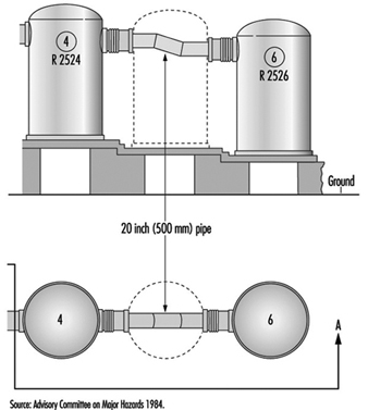
The explosion of a large cloud of cyclohexane in Flixborough (UK) in 1974, which killed 28 persons and caused extensive plant damage, serves as a very instructive case. The triggering event was the breakdown of a temporary pipe serving as a substitute in a reactor unit. The accident was “caused” by a piece of hardware breaking down, but on closer investigation it was revealed that the breakdown followed from overload, and that the temporary construction was in fact inadequate for its intended use. After two months’ service, the pipe was exposed to bending forces due to a slight pressure rise of the 10-bar (106 Pa) cyclohexane content at about 150°C. The two bellows between the pipe and the nearby reactors broke and 30 to 50 tonnes of cyclohexane was released and soon ignited, probably by a furnace some distance from the leak. (See figure 1.) A very readable account of the case is found in Kletz (1988).
Figure 1. Temporary connection between tanks at Flixborough
Hazard Analysis
The methods that have been developed to find the risks that may be relevant to a piece of equipment, to a chemical process or to a certain operation are referred to as “hazard analysis”. These methods ask questions such as: “What may possibly go wrong?” “Could it be serious?” and “What can be done about it?” Different methods of conducting the analyses are often combined to achieve a reasonable coverage, but no such set can do more than guide or assist a clever team of analysts in their determinations. The main difficulties with hazard analysis are as follows:
- availability of relevant data
- limitations of models and calculations
- new and unfamiliar materials, constructions and processes
- system complexity
- limitations on human imagination
- limitations on practical tests.
To produce usable risk evaluations under these circumstances it is important to stringently define the scope and the level of “ambitiousness” appropriate to the analysis at hand; for example, it is clear that one does not need the same sort of information for insurance purposes as for design purposes, or for the planning of protection schemes and the construction of emergency arrangements. Generally speaking, the risk picture must be filled in by mixing empirical techniques (i.e., statistics) with deductive reasoning and a creative imagination.
Different risk evaluation tools - even computer programs for risk analysis—can be very helpful. The hazard and operability study (HAZOP) and the failure mode and effect analysis (FMEA ) are commonly used methods for investigating hazards, especially in the chemical industry. The point of departure for the HAZOP method is the tracing of possible risk scenarios based on a set of guide words; for each scenario one has to identify probable causes and consequences. In the second stage, one tries to find means for reducing the probabilities or mitigating the consequences of those scenarios judged to be unacceptable. A review of the HAZOP method can be found in Charsley (1995). The FMEA method asks a series of “what if” questions for every possible risk component in order to thoroughly determine whatever failure modes may exist and then to identify the effects that they may have on system performance; such an analysis will be illustrated in the demonstration example (for a gas system) presented later in this article.
Fault trees and event trees and the modes of logical analysis proper to accident causation structures and probability reasoning are in no way specific to the analysis of hardware hazards, as they are general tools for system risk evaluations.
Tracing hardware hazards in an industrial plant
To identify possible hazards, information on construction and function can be sought from:
- actual equipment and plant
- substitutes and models
- drawings, electrical diagrams, piping and instrumentation (P/I) diagrams, etc.
- process descriptions
- control schemes
- operation modes and phases
- work orders, change orders, maintenance reports, etc.
By selecting and digesting such information, analysts form a picture of the risk object itself, its functions and its actual use. Where things are not yet constructed - or unavailable for inspection - important observations cannot be made and the evaluation must be based entirely on descriptions, intentions and plans. Such evaluation might seem rather poor, but in fact, most practical risk evaluations are made this way, either in order to seek authoritative approval for applications to undertake new construction, or to compare the relative safety of alternative design solutions. Real life processes will be consulted for the information not shown on the formal diagrams or described verbally by interview, and to verify that the information gathered from these sources is factual and represents actual conditions. These include the following:
- actual practice and culture
- additional failure mechanisms/construction details
- “sneak paths” (see below)
- common error causes
- risks from external sources/missiles
- particular exposures or consequences
- past incidents, accidents and near accidents.
Most of this additional information, especially sneak paths, is detectable only by creative, skilled observers with considerable experience, and some of the information would be almost impossible to trace with maps and diagrams. Sneak paths denote unintended and unforeseen interactions between systems, where the operation of one system affects the condition or operation of another system through other ways than the functional ones. This typically happens where functionally different parts are situated near each other, or (for example) a leaking substance drips on equipment beneath and causes a failure. Another mode of a sneak path’s action may involve the introduction of wrong substances or parts into a system by means of instruments or tools during operation or maintenance: the intended structures and their intended functions are changed through the sneak paths. By common-mode failures one means that certain conditions - like flooding, lightning or power failure - can disturb several systems at once, perhaps leading to unexpectedly large blackouts or accidents. Generally, one tries to avoid sneak-path effects and common-mode failures through proper layouts and introducing distance, insulation and diversity in working operations.
A Hazards Analysis Case: Gas Delivery from a Ship to a Tank
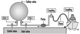
Figure 2 shows a system for delivery of gas from a transport ship to a storage tank. A leak could appear anywhere in this system: ship, transmission line, tank or output line; given the two tank reservoirs, a leak somewhere on the line could remain active for hours.
Figure 2. Transmission line for delivery of liquid gas from ship to storage tank
The most critical components of the system are the following:
- the storage tank
- the pipeline or hose between the tank and the ship
- other hoses, lines, valves and connections
- the safety valve on the storage tank
- the emergency shut-down valves ESD 1 and 2.
A storage tank with a large inventory of liquid gas is put at the top of this list, because it is difficult to stop a leak from a tank on short notice. The second item on the list - the connection to the ship - is critical because leaks in the pipe or hose and loose connections or couplings with worn gaskets, and variations among different ships, could release product. Flexible parts like hoses and bellows are more critical than rigid parts, and require regular maintenance and inspection. Safety devices like the pressure release valve on the top of the tank and the two emergency shut-down valves are critical, since they must be relied upon to reveal latent or developing failures.
Up to this point, the ranking of system components as to their importance with respect to reliability has been of a general nature only. Now, for analytical purposes, attention will be drawn to the particular functions of the system, the chief one of course being the movement of liquefied gas from the ship to the storage tank until the connected ship tank is empty. The overriding hazard is a gas leak, the possible contributory mechanisms being one of more of the following:
- leaking couplings or valves
- tank rupture
- rupture of pipe or hose
- tank breakdown.
Application of the FMEA method
The central idea of the FMEA approach, or “what if” analysis, is to record explicitly, for each component of the system, its failure modes, and for every failure to find the possible consequences to the system and to the environment. For standard components like a tank, pipe, valve, pump, flowmeter and so on, the failure modes follow general patterns. In the case of a valve, for instance, failure modes could include the following conditions:
- The valve cannot close on demand (there is reduced flow through an “open” valve).
- The valve leaks (there is residual flow through a “closed” valve).
- The valve cannot open on demand (the valve position oscillates).
For a pipeline, failure modes would consider items such as:
- a reduced flow
- a leak
- a flow stopped due to blockage
- a break in the line.
The effects of leaks seem obvious, but sometimes the most important effects may not be the first effects: what happens for example, if a valve is stuck in a half-open position? An on-off valve in the delivery line that does not open completely on demand will delay the tank filling process, a non-dangerous consequence. But if the “stuck half-open” condition arises at the same time that a closing demand is made, at a time when the tank is almost full, overfilling might result (unless the emergency shut-down valve is successfully activated). In a properly designed and operated system, the probability of both these valves being stuck simultaneously will be kept rather low.
Plainly a safety valve’s not operating on demand could mean disaster; in fact, one might justifiably state that latent failures are constantly threatening all safety devices. Pressure relief valves, for instance, can be defective due to corrosion, dirt or paint (typically due to bad maintenance), and in the case of liquid gas, such defects in combination with the temperature decrease at a gas leak could produce ice and thereby reduce or perhaps stop the flow of material through a safety valve. If a pressure relief valve does not operate on demand, pressure may build up in a tank or in connected systems of tanks, eventually causing other leaks or tank rupture.
For simplicity, instruments are not shown on figure 2; there will of course be instruments related to pressure, flow and temperature, which are essential parameters for monitoring the system state, relevant signals being transmitted to operator consoles or to a control room for control and monitoring purposes. Furthermore, there will be supply lines other than those intended for materials transport - for electricity, hydraulics and so forth - and extra safety devices. A comprehensive analysis must go through these systems as well and look for the failure modes and effects of these components also. In particular, the detective work on common-mode effects and sneak paths requires one to construct the integral picture of main system components, controls, instruments, supplies, operators, working schedules, maintenance and so on.
Examples of common-mode effects to consider in connection with gas systems are addressed by such questions as these:
- Are activation signals for delivery valves and emergency shut-down valves transmitted on a common line (cable, cabling channels)?
- Do two given valves share the same power line?
- Is maintenance performed by the same person according to a given schedule?
Even an excellently designed system with redundancy and independent power lines can suffer from inferior maintenance, where, for example, a valve and its back-up valve (the emergency shut-down valve in our case) have been left in a wrong state after a test. A prominent common-mode effect with an ammonia-handling system is the leak situation itself: a moderate leak can make all manual operations on plant components rather awkward - and delayed - due to the deployment of the required emergency protection.
Summary
The hardware components are very seldom the guilty parts in accident development; rather, there are root causes to be found in other links of the chain: wrong concepts, bad designs, maintenance errors, operator errors, management errors and so on. Several examples of the specific conditions and acts that may lead to failure development have already been given; a broad collection of such agents would take account of the following:
- collision
- corrosion, etching
- excessive loads
- failing support and aged or worn-out parts
- low-quality welding jobs
- missiles
- missing parts
- overheating or chilling
- vibration
- wrong construction material used.
Controlling the hardware hazards in a working environment requires the review of all possible causes and respect for the conditions that are found to be critical with the actual systems. The implications of this for the organization of risk management programmes are dealt with in other articles, but, as the foregoing list clearly indicates, the monitoring and control of hardware conditions can be necessary all the way back to the choice of concepts and designs for the selected systems and processes.
Hazard Analysis: Organizational Factors - mort
Through industrialization, workers became organized in factories as the utilization of energy sources such as the steam engine became possible. As compared to traditional handicraft, mechanized production, with sources of higher energy at its disposal, presented new risks of accidents. As the amount of energy increased, workers were removed from the direct control of these energies. Decisions that affected safety were often made at the management level rather than by those directly exposed to these risks. At this stage of industrialization, the need for safety management became evident.
In the late 1920s, Heinrich formulated the first comprehensive theoretical framework for safety management, which was that safety should be sought through management decisions based on identification and analysis of accident causes. At this point in the development of safety management, accidents were attributed to failures at the worker-machine system level - that is, to unsafe acts and unsafe conditions.
Subsequently, various methodologies were developed for the identification and assessment of accident risks. With MORT (Management Oversight and Risk Tree), the focus shifted to the higher orders of control of accident risks - that is, to the control of conditions at the management level. The initiative to develop MORT was taken in the late 1960s by the US Energy Research and Development Administration, which wanted to improve their safety programmes in order to reduce their losses due to accidents.
The MORT Diagram and Underlying Principles
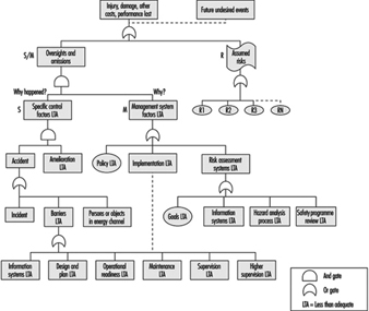
The intent of MORT was to formulate an ideal safety management system based on a synthesis of the best safety programme elements and safety management techniques then available. As the principles underlying the MORT initiative were applied to the contemporary state of the art in safety management, the largely unstructured safety literature and expertise took on the form of an analytical tree. The first version of the tree was published in 1971. Figure 1 shows the basic elements of the version of the tree that was published by Johnson in 1980. The tree also appears in a modified form in later publications on the subject of the MORT concept (see, for example, Knox and Eicher 1992).
Figure 1. A version of the MORT analytical tree
The MORT Diagram
MORT is used as a practical tool in accident investigations and in evaluations of existing safety programmes. The top event of the tree in figure 1 (Johnson 1980) represents the losses (experienced or potential) due to an accident. Below this top event are three main branches: specific oversights and omissions (S), management oversights and omissions (M) and assumed risks (R). The R-branch consists of assumed risks, which are events and conditions that are known to management and that have been evaluated and accepted at the proper management level. Other events and conditions that are revealed through the evaluations following the S- and M-branches are denoted “less than adequate” (LTA).
The S-branch focuses on the events and conditions of the actual or potential occurrence. (In general, time is shown as one reads from left to right, and the sequence of causes is shown as one reads from bottom to top.) Haddon’s strategies (1980) for the prevention of accidents are key elements in this branch. An event is denoted an accident when a target (a person or object) is exposed to an uncontrolled transfer of energy and sustains damage. In the S-branch of MORT, accidents are prevented through barriers. There are three basic types of barriers: (1) barriers that surround and confine the energy source (the hazard), (2) barriers that protect the target and (3) barriers that separate the hazard and the target physically or in time or space. These different types of barriers are found in the development of the branches below the accidental event. Amelioration relates to the actions taken after the accident to limit the losses.
At the next level of the S-branch, factors are recognized which relate to the different phases of the life cycle of an industrial system. These are the project phase (design and plan), start up (operational readiness) and operation (supervision and maintenance).
The M-branch supports a process in which specific findings from an accident investigation or safety programme evaluation are made more general. Events and conditions of the S-branch thus often have their counterparts in the M-branch. When engaged with the system at the M-branch, the analyst’s thinking is expanded to the total management system. Thus, any recommendations will affect many other possible accident scenarios as well. The most important safety management functions can be found in the M-branch: the setting of policy, implementation and follow-up. These are the same basic elements that we find in the quality assurance principles of the ISO 9000 series published by the International Organization for Standardization (ISO).
When the branches of the MORT diagram are elaborated in detail, there are elements from such different fields as risk analysis, human factors analysis, safety information systems and organizational analysis. In total, about 1,500 basic events are covered by the MORT diagram.
Application of the MORT Diagram
As indicated, the MORT diagram has two immediate uses (Knox and Eicher 1992): (1) to analyse management and organizational factors relative to an accident that has happened and (2) to evaluate or audit a safety programme in relation to a significant accident that has the potential of occurring. The MORT diagram functions as a screening tool in planning the analyses and evaluations. It is also used as a checklist for comparison of actual conditions with the idealized system. In this application, MORT facilitates checking the completeness of the analysis and avoiding personal biases.
At bottom, MORT is made up of a collection of questions. Criteria that guide judgements as to whether specific events and conditions are satisfactory or less than adequate are derived from these questions. In spite of the directive design of the questions, the judgements made by the analyst are partly subjective. It has thus become important to ensure an adequate quality and degree of intersubjectivity among MORT analyses made by different analysts. For example, in the United States, a training programme is available for certification of MORT analysts.
Experiences with MORT
The literature on evaluations of MORT is sparse. Johnson reports significant improvements in the comprehensiveness of accident investigations after the introduction of MORT (Johnson 1980). Deficiencies at the supervisory and management levels were revealed more systematically. Experience has also been gained from evaluations of MORT applications within Finnish industry (Ruuhilehto 1993). Some limitations have been identified in the Finnish studies. MORT does not support the identification of immediate risks due to failures and disturbances. Furthermore, no capability for setting priorities is built into the MORT concept. Consequently, the results of MORT analyses need further evaluation to translate them into remedial actions. Finally, experience shows that MORT is time-consuming and requires expert participation.
Aside from its ability to focus on organizational and management factors, MORT has the further advantage of connecting safety with normal production activities and general management. The application of MORT will thus support general planning and control, and help reduce the frequency of production disturbances as well.
Associated Safety Management Methods and Techniques
With the introduction of the MORT concept in the early 1970s, a development programme started in the United States. The focal point for this programme has been the System Safety Development Center in Idaho Falls. Different MORT-associated methods and techniques in such areas as human factors analysis, safety information systems and safety analysis have resulted from this programme. An early example of a method arising from the MORT development programme is the Operational Readiness Program (Nertney 1975). This programme is introduced during the development of new industrial systems and modifications of existing ones. The aim is to ensure that, from the safety management point of view, the new or modified system is ready at the time of start-up. A condition of operational readiness presupposes that the necessary barriers and controls have been installed in the new system’s hardware, personnel and procedures. Another example of a MORT programme element is the MORT-based root cause analysis (Cornelison 1989). It is used to identify the basic safety management problems of an organization. This is done by relating the specific findings of the MORT analyses to 27 different generic safety management problems.
Although MORT is not intended for use directly in the collection of information during accident investigations and safety audits, in Scandinavia, the MORT questions have served as a basis for the development of a diagnostic tool used for this purpose. It is called the Safety Management and Organization Review Technique, or SMORT (Kjellén and Tinmannsvik 1989). A SMORT analysis advances backwards in steps, starting from the specific situation and ending at the general management level. The starting point (level 1) is an accident sequence or a risk situation. At level 2, the organization, system planning and technical factors related to daily operation are scrutinized. The subsequent levels include design of new systems (level 3) and higher management functions (level 4). Findings on one level are extended to the levels above. For example, results related to the accident sequence and to daily operations are used in the analysis of the company’s organization and routines for project work (level 3). Results at level 3 will not affect safety in existing operations but may be applied to the planning of new systems and modifications. SMORT also differs from MORT in the way findings are identified. At level 1, these are observable events and conditions that deviate from generally accepted norms. When organizational and management factors are brought into the analysis at levels 2 to 4, the findings are identified through value judgements made by an analysis group and verified through a quality control procedure. The aim is to ensure a mutually shared understanding of the organizational problems.
Summary
MORT has been instrumental in developments within safety management since the 1970s. It is possible to track the influence of MORT to such areas as safety research literature, literature on safety management and audit tools, and legislation on self-regulation and internal control. In spite of this impact, its limitations must be carefully considered. MORT and associated methods are normative in the sense that they prescribe how safety management programmes should be organized and executed. The ideal is a well-structured organization with clear and realistic goals and well-defined lines of responsibility and authority. MORT is thus best suited for large and bureaucratic organizations.
Workplace Inspection and Regulatory Enforcement
Inspection Systems
Auditing has been defined as “the structured process of collecting independent information on the efficiency, effectiveness and reliability of the total safety management system and drawing up plans for corrective action” (Successful Health & Safety Management 1991).
The workplace inspection therefore is not only the final stage in setting up a safety management programme but is also a continuing process in its maintenance. It can be conducted only where a properly devised management system for safety has been established. Such a system first envisages a formal policy statement from management setting out its principles for creating a healthy and safe working environment and then establishing the mechanisms and the structures within the organization whereby these principles will be effectively implemented. Management must furthermore be committed to providing adequate resources, both human and financial, to support the system’s mechanisms and structures. Thereafter, there must be detailed planning for safety and health, and the defining of measurable goals. Systems must be devised to ensure that safety and health performance in practice can be measured against established norms and against previous achievements. Only when this structure is in place and is operating can an effective management audit system be applied.
Complete safety and health management systems can be devised, produced and implemented from within the resources of larger enterprises. Additionally, there are a number of safety management control systems which are available from consultants, insurance companies, government agencies, associations and specialist companies. It is a matter for the enterprise to decide whether it should produce its own system or obtain outside services. Both alternatives are capable of producing excellent results if there is a genuine commitment by management to apply them diligently and to make them work. But for their success, they do depend heavily on the quality of the audit system.
Management Inspections
The inspection procedure must be as painstaking and objective as the company’s financial inspection. The inspection must first determine whether the company’s statement of policy on safety and health is properly reflected in the structures and mechanisms created to implement it; if not, then the inspection may recommend that the fundamental policy be reappraised or suggest adjustments or alterations to the existing structures and mechanisms. A similar process must be applied to safety and health planning, to the validity of the goal-setting norms, and to the measurement of performance. The results of any inspection must be considered by the top management of the enterprise, and any correctives must be endorsed and implemented through that authority.
In practice it is undesirable, and often impractical, to undertake a complete inspection of all of a system’s features and their application throughout every department of the enterprise at one time. More usually, the inspection procedure concentrates on one feature of the total safety management system throughout the plant, or alternatively on the application of all the features in one department or even subdepartment. But the objective is to cover all the features in all departments over an agreed period in order to validate the results.
To this extent management inspection should be regarded as a continuous process of vigilance. The need for objectivity is clearly of considerable importance. If inspections are conducted in-house then there must be a standardized inspection procedure; inspections should be undertaken by staff who have been properly trained for this purpose; and those selected as inspectors must not assess the departments in which they normally work, nor should they assess any other work in which they have a personal involvement. Where reliance is placed on consultants this problem is minimized.
Many major companies have adopted this type of system, either devised internally or obtained as a proprietary scheme. When the systems have been carefully followed through from policy statement to inspection, feedback and corrective actions, a substantial reduction in accident rates, which is the prime justification for the procedure, and increased profitability, which is a welcome secondary outcome, should result.
Inspections by Inspectorates
The legal framework which is designed to afford protection to people at work must be properly administered and effectively applied if the purpose of the regulatory legislation is to be achieved. Most countries have therefore adopted the broad model of an inspection service which has the duty of ensuring that safety and health legislation is enforced. Many countries see safety and health issues as part of a complete labour relations package covering industrial relations, wages and holiday agreements, and social benefits. In this model, safety and health inspections are one element of the labour inspector’s duties. A different model also exists in which the state inspectorate is exclusively concerned with safety and health legislation, so that workplace inspections concentrate solely on this aspect. Further variations are evident in the division of the inspection functions between either a national inspectorate or a regional/provincial inspectorate, or indeed, as in Italy and the United Kingdom, for example, as a working combination of both national and regional inspectorates. But whichever model is adopted, the essential function of the inspectorate is to determine compliance with the legislation by a programme of planned inspections and investigations at the workplace.
There can be no effective inspection system unless those who undertake this work are given adequate powers to carry it out. There is much common ground among inspectorates as regards the powers given to them by their legislators. There must always be the right of entry to premises, which is clearly fundamental for inspection. Thereafter there is the legal right to examine relevant documents, registers and reports, to interview members of the workforce either individually or collectively, to have unrestricted access to trade union representatives at the workplace, to take samples of substances or materials at use in the workplace, to take photographs and, if appropriate, to take written statements from people working at the premises.
Additional powers are often provided to enable inspectors to rectify conditions which might be an immediate source of danger or ill health to the workforce. Again there is a wide variety of practices. Where standards are so poor that there is an imminent risk of danger to the workforce, then an inspector may be authorized to serve a legal document on the spot prohibiting the use of the machinery or plant, or stopping the process until the risk has been effectively controlled. For a lower order of risk, inspectors can issue a legal notice formally requiring that measures be taken within a given time to improve standards. These are effective ways of rapidly improving working conditions, and are often a form of enforcement preferable to formal court proceedings, which may be cumbersome and slow in securing remediation.
Legal proceedings have an important place in the hierarchy of enforcement. There is an argument that because court proceedings are simply punitive and do not necessarily result in changing attitudes to safety and health at work, they should therefore be invoked only as a last resort when all other attempts at securing improvements have failed. But this view has to be set against the fact that where legal requirements have been ignored or disregarded, and where people’s safety and health have been significantly put at risk, then the law must be enforced and the courts must decide the issue. There is the further argument that those enterprises which disregard safety and health legislation may thereby enjoy an economic advantage over their competitors, who provide adequate resources to comply with their legal duties. Prosecution of those who persistently disregard their duties is therefore a deterrent to the unscrupulous, and an encouragement to those who try to observe the law.
Every inspection service has to determine the proper balance between providing advice and enforcing the law in the course of inspection work. A special difficulty emerges in connection with the inspection of small enterprises. Local economies, and indeed national economies, are often underpinned by industrial premises each employing fewer than 20 people; in the case of agriculture, the employment figure per unit is very much less. The function of the inspectorate in these cases is to use the workplace inspection to provide information and advice not only on legal requirements, but on practical standards and effective ways of meeting those standards. The technique must be to encourage and stimulate, rather than to immediately enforce the law by punitive action. But even here the balance is a difficult one. People at work are entitled to safety and health standards irrespective of the size of the enterprise, and it would therefore be wholly misguided for an inspection service to ignore or minimize risks and to curtail or even forgo enforcement simply to nurture the existence of the economically fragile small enterprise.
Consistency of Inspections
In the view of the complex nature of their work - with its combined needs for legal, prudential, technical and scientific skills, inspectors do not - indeed should not - adopt a mechanistic approach to inspection. This constraint, combined with a difficult balance between the advisory and enforcement functions, creates yet another concern, that of the consistency of inspection services. Industrialists and trade unions have a right to expect a consistent application of standards, whether technical or legal, by inspectors across the country. In practice this is not always easy to achieve, but it is something for which the enforcing authorities must always strive.
There are ways of achieving an acceptable consistency. First, the inspectorate should be as open as possible in publishing its technical standards and in publicly setting out its enforcement policies. Second, through training, the application of peer review exercises, and internal instructions, it should be able both to recognize a problem and to provide systems to deal with it. Finally, it should ensure that there are procedures for industry, the workforce, the public and the social partners to secure redress if they have a legitimate grievance over inconsistency or other forms of maladministration associated with inspection.
Frequency of Inspections
How frequently should the inspectorates undertake inspections of the workplace? Again there is considerable variation in the way this question may be answered. The International Labour Organization (ILO) holds the view that the minimum requirement should be that every workplace should receive an inspection from the enforcing authorities at least once each year. In practice, few countries manage to produce a programme of work inspection which meets this objective. Indeed, since the major economic depression in the late 1980s some governments have been curtailing inspection services by budget limitations that result in cutbacks in the number of inspectors, or by restrictions on recruiting new staff to replace those who retire.
There are different approaches to determine how frequently inspections should be made. One approach has been purely cyclical. Resources are deployed to provide inspection of all premises on a 2-yearly, or more likely a 4-yearly, basis. But this approach, though possibly having the appearance of equity, treats all premises as the same regardless of size or risk. Yet enterprises are manifestly diverse as regards safety and health conditions, and to the extent that they differ, this system may be regarded as mechanistic and flawed.
A different approach, adopted by some inspectorates, has been to attempt to draw up a programme of work based on hazard; the greater the hazard either to safety or health, the more frequent the inspection. Hence resources are applied by the inspectorate to those places where the potential for harm to the workforce is the greatest. Although this approach has merits, there are still considerable problems associated with it. First, there are difficulties in accurately and objectively assessing hazard and risk. Second, it extends very considerably the intervals between inspections of those premises where hazards and risks are considered to be low. Therefore, extended periods may elapse during which many of the workforce may have to forgo that sense of security and assurance which inspection can provide. Furthermore, the system tends to presume that hazards and risks, once assessed, do not radically change. This is far from being the case, and there is the danger that a low-rated enterprise may change or develop its production in such a way as to increase hazards and risk without the inspectorate’s being aware of the development.
Other approaches include inspections based on facility injury rates which are higher than the national averages for the particular industry, or immediately following a fatal injury or major catastrophe. There are no short and easy answers to the problem of determining the frequency of inspection, but what seems to be happening is that inspection services in many countries are too often significantly under-resourced, with the result that the real protection to the workforce afforded by the service is being progressively eroded.
Inspection Goals
Inspection techniques in the workplace vary according to the size and complexity of the enterprise. In smaller companies, the inspection will be comprehensive and will assess all hazards and the extent to which the risks arising from the hazards have been minimized. The inspection will therefore ensure that the employer is fully aware of safety and health problems and is given practical guidance on how they may be addressed. But even in the smallest enterprise the inspectorate should not give the impression that fault-finding and the application of suitable remedies are the function of the inspectorate and not of the employer. Employers must be encouraged by inspection to control and effectively manage safety and health problems, and they must not abdicate their responsibilities by awaiting an inspection from the enforcement authorities before taking needed action.
In larger companies, the emphasis of inspection is rather different. These companies have the technical and financial resources to deal with safety and health problems. They should devise both effective management systems to resolve the problems, as well as management procedures to check that the systems are working. In these circumstances, the inspection emphasis should therefore be on checking and validating the management control systems found at the workplace. The inspection should therefore not be an exhaustive examination of all items of plant and equipment to determine their safety, but rather to use selected examples to test the effectiveness or otherwise of the management systems for ensuring safety and health at work.
Worker Involvement in Inspections
Whatever the premises, a critical element in any type of inspection is contact with the workforce. In many smaller premises, there may be no formal trade union structure or indeed any workforce organization at all. However, to ensure the objectivity and acceptance of the inspection service, contact with individual workers should be an integral part of the inspection. In larger enterprises, contact should always be made with trade union or other recognized worker representatives. Legislation in some countries (Sweden and the United Kingdom, for example) gives official recognition and powers to trade union safety representatives, including the right to make workplace inspections, to investigate accidents and dangerous occurrences and in some countries (though this is exceptional) to stop plant machinery or the production process if it is imminently dangerous. Much useful information can be gained from these contacts with the workers, which should feature in every inspection, and certainly whenever the inspectorate is conducting an inspection as the result of an accident or a complaint.
Inspection Findings
The final element in an inspection is to review the inspection findings with the most senior member of management on the site. Management has the prime responsibility to comply with legal requirements on safety and health, and therefore no inspection should be complete without management’s being fully aware of the extent to which it has met those duties, and what needs to be done to secure and maintain proper standards. Certainly if any legal notices are issued as a result of an inspection, or if legal proceedings are likely, then senior management must be aware of this state of affairs at the earliest possible stage.
Company Inspections
Company inspections are an important ingredient in maintaining sound standards of safety and health at work. They are appropriate to all enterprises and, in larger companies, may be an element in the management inspection procedure. For smaller companies, it is essential to adopt some form of regular company inspection. Reliance should not be placed on the inspection services provided by the inspectorates of the enforcing authorities. These are usually far too infrequent, and should serve largely as a stimulus to improve or maintain standards, rather than be the primary source for evaluating standards. Company inspections can be undertaken by consultants or by companies who specialize in this work, but the current discussion will concentrate on inspection by the enterprise’s own personnel.
How frequently should company inspections be made? To some degree the answer is dependent on the hazards associated with the work and the complexity of the plant. But even in low-risk premises there should be some form of inspection on a regular (monthly, quarterly, etc.) basis. If the company employs a safety professional, then clearly the organization and the conduct of the inspection must be an important part of this function. The inspection should usually be a team effort involving the safety professional, the departmental manager or foreman, and either a trade union representative or a qualified worker, such as a safety committee member. The inspection should be comprehensive; that is to say, a close examination should be made both of the safety software (for example, systems, procedures and work permits) and the hardware (for example, machinery guarding, fire-fighting equipment, exhaust ventilation and personal protective equipment). Particular attention should be paid to “near misses” - those incidents which do not result in damages or personal injury but which have the imminent potential for serious accidental injuries. There is an expectation that after an accident resulting in absence from work, the inspection team would immediately convene to investigate the circumstances, as a matter outside the normal cycle of inspection. But even during routine workshop inspection the team should also consider the extent of minor accidental injuries which have occurred in the department since the previous inspection.
It is important that company inspections should not seem to be consistently negative. Where faults exist it is important that they be identified and rectified, but it is equally important to commend the maintenance of good standards, to comment positively on tidiness and good housekeeping, and to reinforce by encouragement those who use personal protective equipment provided for their safety. To complete the inspection a formal written report should be made of the significant deficiencies found. Particular attention should be drawn to any shortcomings which have been identified in previous inspections but have not yet been corrected. Where there exists a works safety council, or a joint management-worker safety committee, the inspection report should be featured as a standing item on the council’s agenda. The report on the inspection must be sent to and discussed with the senior management of the enterprise, who should then determine whether action is required and, if so, authorize and support such action.
Even the smallest companies, where there is no safety professional, and where trade unions may not exist, should consider company inspections. Many inspectorates have produced very simple guidelines illustrating the basic concepts of safety and health, their application to a range of industries, and practical ways in which they can be applied in even the smallest enterprises. Many safety associations specifically target small businesses with publications (often free) which provide the basic information to establish safe and healthy working conditions. Armed with this sort of information and with the expenditure of very little time, the proprietor of a small business can establish reasonable standards, and can thus perhaps obviate the sort of accidents which can happen to the workforce in even the smallest business.
Analysis and Reporting: Accident Investigation
It is a paradox that the prevention of work-related accidents did not emerge very early as an absolute necessity, since health and safety is fundamental to work itself. In fact it was not until the beginning of the twentieth century that accidents at work ceased to be considered inevitable and their causation became a subject to be investigated and used as a basis for prevention. However, accident investigation long remained cursory and empirical. Historically, accidents were first conceived of as simple phenomena—that is, as resulting from a single (or principal) cause and a small number of subsidiary causes. It is now recognized that accident investigation, which is aimed at identifying the causes of the phenomenon so as to avert its reoccurrence, depends both on the concept underlying the process of investigation and on the complexity of the situation to which it is applied.
Causes of Accidents
It is indeed true that in the most precarious situations, accidents are often the result of a fairly simple sequence of a few causes that can be rapidly traced to basic technical problems that even a summary analysis can reveal (equipment badly designed, working methods undefined, etc.). On the other hand, the more closely that the material elements of work (machines, installations, the arrangement of the workplace, etc.) conform with the requirements of safe work procedures, standards and regulations, the safer the work situation becomes. The result is that an accident can then occur only when a group of exceptional conditions are present simultaneously—conditions that are becoming ever more numerous. In such cases, the injury or damage appears as the final result of a frequently complex network of causes. This complexity is actually evidence of progress in prevention, and requires appropriate methods of investigation. Table 1 lists the principal concepts of the accident phenomenon, their characteristics and implications for prevention.
Table 1. Principal concepts of the accident phenomenon, their characteristics and the implications for prevention
|
Concept or “accident phenomenon” |
Significant elements (objectives, procedures, limits, etc.) |
Main consequences for prevention |
|
Basic concept (accident as |
The objective is to identify “the” single or main cause |
Simple prevention measures concerning the immediate antecedent of the injury (individual protection, instructions about taking care, protection of dangerous machines) |
|
Concept focused on regulatory measures |
Focus on looking for who is responsible; the “enquiry” essentially identifies infringements and faults Rarely concerned about the conditions generating the situations examined |
Prevention usually limited to reminders about existing regulatory requirements or formal instructions |
|
Linear (or quasi-linear) concept (“domino” model) |
Identification of a chronological succession of “dangerous conditions” and “dangerous acts” |
Conclusions generally concerned with the dangerous acts |
|
Multifactorial concept |
Exhaustive research to gather the facts (circumstances, causes, factors, etc.) |
Concept not conducive to the search for solutions case by case (clinical analysis) and better adapted to the identification of statistical aspects (trends, tables, graphs, etc.) |
|
Systematic concept |
Identification of the network of factors of each accident |
Methods centred on clinical analysis |
Nowadays, a work accident is generally viewed as an index (or symptom) of dysfunction in a system consisting of a single production unit, such as a factory, workshop, team or work position. It is the nature of a system that its analysis requires the investigator to examine not only the elements that make up the system but also their relationships with one another and with the work environment. Within the framework of a system, the accident investigation seeks to trace to its origins the sequence of basic dysfunctions that have resulted in the accident and, more generally, the network of antecedents of the undesired event (accident, near accident or incident).
The application of methods of this kind, such as the STEP method (sequentially timed events plotting procedures) and the “tree of causes” method (similar to fault or event trees analyses), allows the accident process to be visualized in the form of an adjusted graph that illustrates the multicausality of the phenomenon. Because these two methods are so similar, it would represent a duplication of effort to describe them both; accordingly, this article concentrates on the tree of causes method and, where applicable, notes its main differences from the STEP method.
Information Useful for the Investigation
The initial phase of the investigation, the gathering of information, must allow the course of the accident to be described in concrete, precise and objective terms. The investigation therefore sets out to ascertain the tangible facts, taking care not to interpret them or to express an opinion about them. These are the antecedents of the accident, of which there are two types:
- those of an unusual nature (changes or variations) in relation to the “normal” or expected course of the work
- those of a permanent nature that have played an active part in the occurrence of the accident through the medium of or in combination with the unusual antecedents.
For example, insufficient protection of a machine (a permanent antecedent) can turn out to be a factor in an accident if it allows the operator to take up a position in a dangerous area in order to deal with a particular incident (unusual antecedent).
The information gathering is carried out at the location of the accident itself as soon as possible after its occurrence. It is preferably carried out by persons who know the operation or process and who try to obtain a precise description of the work without limiting themselves to the immediate circumstances of the damage or injury. The investigation is initially effected mainly by means of interviews, if possible with the worker or operator, victims and eyewitnesses, other members of the work team, and the hierarchical supervisors. If appropriate it is completed by means of a technical investigation and the use of outside expertise.
The investigation seeks to identify, in order of priority, the unusual antecedents, and to determine their logical connections. An effort is made at the same time to reveal the permanent antecedents that have allowed the accident to occur. In this way the investigation is able to go back to a stage more remote than the immediate antecedents of the accident. These more remote antecedents may concern individuals, their tasks, the equipment that they use, the environment in which they function and the safety culture. By proceeding in the way just described, it is generally possible to draw up a lengthy list of antecedents, but it will usually be difficult to make immediate use of the data. The interpretation of the data is made possible thanks to a graphic representation of all the antecedents involved in the genesis of the accident—that is, a tree of causes.
Constructing a Tree of Causes
The tree of causes presents all the antecedents that have been gathered which have given rise to the accident, as well as the logical and chronological links that connect them; it is a representation of the network of antecedents that have directly or indirectly caused the injury. The tree of causes is constructed starting from the end-point of the event - that is, the injury or damage—and working backwards toward the cause by systematically asking the following questions for each antecedent that has been gathered:
- By which antecedent X was antecedent Y directly caused?
- Was antecedent X sufficient in itself to give rise to antecedent Y?
- If not, have there been other antecedents (X1, X2 Xn) that were equally necessary in order to give rise directly to antecedent Y?
This set of questions can reveal three types of logical connection, summarized in figure 1, among the antecedents.
Figure 1. Logical links used in the "tree of causes" method
The logical coherence of the tree is checked by asking the following questions for each antecedent:
- If X had not taken place, would Y nevertheless have occurred?
- In order for Y to occur, was X, and only X, necessary?
Moreover, the construction of the tree of causes in itself induces the investigators to pursue the information-gathering, and therefore the investigation, to a point well before the accident occurred. When completed, the tree represents the network of antecedents that have given rise to the injury—they are in fact the accident factors. As an example, the accident summarized below produced the tree of causes shown in figure 2.
Figure 2. Tree of causes of an accident suffered by an apprentice mechanic when remounting an engine in a car
Accident Summary Report: An apprentice mechanic, recently recruited, had to work alone in an emergency. A worn sling was being used to suspend an engine that had to be remounted, and during this operation the sling broke and the engine fell and injured the mechanic’s arm.
Analysis by the STEP Method
According to the STEP method (figure 3), each event is set out graphically so as to show the chronological order of its appearance, keeping one line per “agent” concerned (an agent is the person or thing that determines the course of events constituting the accident process). Each event is described precisely by indicating its beginning, duration, starting and ending place and so on. When there are several plausible hypotheses, the investigator can show them in the network of events by using the logical relationship “or”.
Figure 3. Example of representation possible by the STEP method
Analysis by the Tree of Causes Method
Making use of the tree of causes for the purposes of accident analysis has two objectives:
- making the reoccurrence of the same accident impossible
- averting the occurrence of more or less similar accidents - that is, accidents whose investigation would reveal common factors with the accidents that have already occurred.
Given the logical structure of the tree, the absence of a single antecedent would have prevented the occurrence of the accident. One judicious prevention measure would therefore suffice, in principle, to satisfy the first objective by preventing the reoccurrence of the same accident. The second objective would require that all the factors discovered should be eliminated, but in practice the antecedents are not all of equal importance for the purposes of prevention. It is therefore necessary to draw up a list of antecedents requiring reasonable and realistic preventive action. If this list is long, a choice has to be made. This choice has more chance of being appropriate if it is made within the framework of a debate between the partners concerned in the accident. Moreover, the debate will gain in clarity to the extent that it is possible to assess the cost-effectiveness of each measure proposed.
Effectiveness of Preventive Measures
The effectiveness of a preventive measure can be judged with the help of the following criteria:
The stability of the measure. The effects of a preventive measure must not disappear with time: informing the operators (in particular, reminding them of instructions) is not a very stable measure because its effects are often transient. The same is moreover true of some protective devices when they are easily removable.
The possibility of integrating safety. When a safety measure is added on - that is, when it does not contribute directly to production - it is said that safety is not integrated. Whenever this is so, it is observed that the measure tends to disappear. Generally speaking, any preventive measure entailing an additional cost for the operator should be avoided, whether it is a physiological cost (increasing the physical or nervous load), a psychological cost, a financial cost (in the case of salary or output) or even a simple loss of time.
The non-displacement of the risk. Some preventive measures may have indirect effects that are detrimental to safety. It is therefore always necessary to foresee the possible repercussions of a preventive measure on the system (job, team or workshop) in which it is inserted.
The possibility of general application (the notion of potential accident factor). This criterion reflects the concern that the same preventive action may be applicable to other jobs than the one affected by the accident under investigation. Whenever possible, an effort should be made to go beyond the particular case that has given rise to the investigation, an effort that often requires a reformulation of the problems discovered. The information obtained from an accident may thus lead to preventive action relating to factors that are unknown but present in other work situations where they have not yet given rise to accidents. For this reason they are called “potential accident factors”. This notion opens the way to the early detection of risks, mentioned later.
The effect on root “causes”. As a general rule, the prevention of accident factors near to the point of injury eliminates certain effects of dangerous situations, while prevention acting well upstream of the injury tends to eliminate the dangerous situations themselves. An in-depth investigation of accidents is justified to the extent that the preventive action is equally concerned with the upstream factors.
The time taken for application. The need to act as rapidly as possible after the occurrence of an accident so as to avoid its reoccurrence is often reflected in the application of a simple preventive measure (an instruction, for example), but this does not eliminate the need for other more lasting and more effective action. Every accident must therefore give rise to a series of proposals whose implementation is the subject of follow-up.
The above criteria are intended to give a better appreciation of the quality of preventive action proposed after each accident investigation. However, the final choice is not made solely on this basis, as other considerations, such as economic, cultural or social ones, must also be taken into account. Finally, the measures decided upon must obviously respect the regulations in force.
Accident Factors
The lessons drawn from each accident analysis deserve to be recorded systematically so as to facilitate passing from knowledge to action. Thus figure 4 consists of three columns. In the left-hand column are noted the accident factors requiring preventive measures. Possible preventive action is described in the middle column for each factor decided upon. After the discussion mentioned above, the action selected is recorded in this part of the document.
Figure 4. Lessons drawn from accidents and the use of these lessons
The right-hand column covers the potential accident factors suggested by the factors listed in the left-hand column: it is considered that each accident factor discovered is often only a particular case of a more general factor known as a potential accident factor. The passage from the particular case to the more general case is often made spontaneously. However, each time that an accident factor is expressed in such a fashion that it is not possible to encounter it elsewhere than in the situation in which it has appeared, a more general formulation must be considered. In doing this, it is necessary to avoid two opposite pitfalls so as to utilize the notion of potential accident factor effectively in the early detection of risks arising later. A formulation that is too circumscribed does not permit systematic detection of the factors, whereas one that is too wide makes the notion unworkable and is of no further practical interest. The detection of potential accident factors thus presupposes their being well formulated. This detection can then be carried out in two ways, which are moreover complementary:
- either by looking for the possible presence of potential factors already known at the level of a job or a wider area (workshop, service)
- or by looking for jobs where a factor already determined may be observed.
Usefulness, Effectiveness and Limitations of Accident Investigation
Usefulness. As compared to non-systematic investigations, methods of accident investigation based on a systematic concept have numerous advantages, which include the following:
- They allow the causal network of each accident to be defined collectively, from which it is easier to devise new preventive measures and foresee their impact without being limited to the direct causes of the injury.
- They provide those involved in the analysis with a richer and more realistic mental representation of the “accident phenomenon” that permits a global understanding of work situations.
- In-depth accident investigations (especially when they are extended to cover incidents and undesired events) can become a means and appropriate occasion for dialogue between management and operators.
Effectiveness. In order to be effective, accident investigation requires that four conditions are satisfied concurrently:
- an evident commitment on the part of the top management of the establishment, who must be able to ensure the systematic implementation of such procedures
- training of the investigators
- management, supervisors and workers fully informed concerning the aims of the investigation, its principles, the requirements of the method and the results expected
- real improvements in safety conditions that will encourage those involved in future investigations.
Limitations. Even when carried out very well, accident investigation suffers from a double limitation:
- It remains a procedure for investigating risks a posteriori (in the manner of systems analysis), with the aim of correcting existing situations. It does not therefore dispense with the need for a priori (prospective) investigations, such as the ergonomic investigation of jobs or, for complex systems, safety investigations.
- The usefulness of accident investigations also varies with the safety level of the establishment where they are applied. In particular, when the safety level is high (the accident rate is low or very low), it is evident that serious accidents result from the conjunction of numerous independent random factors that are relatively harmless from the safety viewpoint when considered outside the context under investigation.
Reporting and Compiling Accident Statistics
The Need for Reporting and Compiling Accident Data
The primary purpose of assembling and analysing occupational accident data is to provide knowledge for use in the prevention of occupational injuries, fatalities and other forms of harm such as toxic exposures with long-term effects. These data are also useful in assessing needs for compensating victims for injuries previously incurred. Additional, more specific purposes for the compilation of accident statistics include the following:
- to estimate the causes and magnitude of accident problems
- to identify and prioritize the need for preventive measures
- to evaluate the effectiveness of preventive measures
- to monitor risks, issue warnings and conduct awareness campaigns
- to provide feedback for those involved in prevention.
Often, an overview of the number of accidents occurring on an annual basis is desired. A frequency is often used for this purpose, comparing the number of accidents to a measure relating to the risk group and expressed, for example, in terms of accidents per 100,000 workers or per 100,000 working hours. Such annual counts serve the purpose of revealing variations in an accident rate from one year to another. However, while they may indicate the sorts of accidents that require the most urgent preventive action, by themselves they do not furnish guidance as to the form that this action should take.
The need for accident information pertains to the following three levels of function that make use of it:
- At the workplace level within the individual enterprise, accident data are used in local safety activities. The best opportunities for tackling specific risk factors are to be found immediately at the workplace itself.
- At the level of authority responsible for legislation, accident data are used to regulate the working environment and to promote safety at the workplace. It is possible not only to exert control over the workplace at this level but also to carry out general statistical analyses for use in overall preventive work.
- At the level of authority responsible for payments of compensation to accident victims, accident data are used to help determine rates.
The Role of the Organization in Compiling Accident Information
In many countries it is a legal requirement that enterprises keep statistics of occupational accidents which result in injury, fatality or toxic exposure to a worker. The purpose of this is usually to call attention to risks that have actually led to these types of accidents, with safety activities focusing chiefly on the particular accident and the study of the event itself. However, it is more common for accident information to be collected and recorded systematically, a function that is ordinarily carried out at a higher level.
Since the actual circumstances of most accidents are special, wholly identical accidents seldom occur, and prevention based on the analysis of the individual accident very readily tends to become a highly specific matter. By systematically compiling accident information it is possible to obtain a broader view of those areas where specific risks are to be found, and to uncover the less obvious factors instrumental in the causation of the accident. Specific work processes, specific work teams or work with specific machinery can give rise to highly circumstantial accidents. However, a close study of the types of accidents associated with a given class of uniform work can disclose such factors as inexpedient work processes, incorrect use of materials, difficult working conditions, or lack of adequate worker instruction. An analysis of numerous recurring accidents will reveal the fundamental factors to be dealt with when preventive action is taken.
Reporting Accident Information to Safety Authorities
Legislation requiring the reporting of occupational accidents varies widely from country to country, with the differences chiefly relating to the classes of employers and others to whom the laws apply. Countries that place significant emphasis on safety at the workplace usually mandate that accident data be reported to the authority responsible for supervising compliance with safety legislation. (In some cases, legislation requires reporting of occupational accidents that result in absence from work, the duration of such absence varying from 1 to 3 days in addition to the day of the accident.) Common to most legislation is the fact that reporting is linked with some sort of penalty or compensation for the consequences of accidents.
For the purpose of supplying a sound foundation for the prevention of occupational accidents, it is necessary to secure accident information pertaining to all sectors and to all types of trades. A basis of comparison should be provided at the national level in order to allow prevention action to be prioritized and in order that knowledge of risks associated with tasks across different sectors may be turned to good account in preventive work. It is therefore recommended that the duty of compiling occupational accident information at the national level apply to all occupational accidents of a designated seriousness, no matter whether they concern employees of firms or the self-employed, persons working at temporary jobs or regular salary earners, or workers in the public or private sectors.
While employers, generally speaking, have a duty to report accidents, it is a duty carried out with varying degrees of enthusiasm. The extent of compliance with the obligation to report accidents depends on the incentives driving the employer to do so. Some countries have a rule, for instance, according to which employers will be compensated for an accident victim’s lost-time pay, an arrangement that gives them good reason to report occupational injuries. Other countries penalize employers who are found to be not reporting accidents. Where these sorts of incentives do not exist, the merely legal obligation binding upon the employer is not always observed. It is moreover recommended that occupational accident information intended for preventive applications be given to the authority responsible for preventive activities, and be kept separate from the compensating authority.
What Information is to be Compiled?
There are three basic classes of information obtainable by means of accident recording:
- Information identifying where the accidents occur - that is, sectors, trades, work processes and so on. This knowledge can be used to determine where preventive action is needed.
- Information showing how the accidents occur, the situations in which they occur and the ways in which the injuries come about. This knowledge can be used to determine the type of preventive action needed.
- Information relating to the nature and seriousness of the injuries, describing, for example, the parts of the body affected and the health consequences of the injuries. Such knowledge is to be used for prioritizing preventive action in order to ensure that action is taken where the risk is highest.
It is necessary to compile a certain basic complement of data to properly document when and where an accident occurs and to analyse how it occurs. At the enterprise level, the data that are collected are more detailed than those assembled at the national level, but reports generated at the local level will contain items of information valuable at all levels. Table 1 illustrates particular sorts of information that might be recorded by way of describing an individual accident. The items especially relevant to the task of preparing statistics relating to the accident are described more fully below.
Table 1. Informational variables characterizing an accident
|
Actions |
Items |
|
Step 1 |
|
|
Activity of the victim: e.g., operating a machine, performing maintenance, driving, walking, etc. |
Component related to the activity of the victim: e.g., power press, tool, vehicle, floor, etc. |
|
Step 2 |
|
|
Deviant action: e.g., explosion, structural failure, trip, lost control of, etc. |
Component related to deviant action: e.g., pressure vessel, wall, cable, vehicle, machine, tool, etc. |
|
Step 3 |
|
|
Action leading to injury: e.g., struck by, crushed, trapped, in contact with, bitten by, etc. |
Agent of injury: e.g., brick, ground, machine, etc. |
Accident identification number. All occupational accidents must be assigned a unique identifying number. It is especially advantageous to use a numerical identifier for the purpose of computerized filing and subsequent processing.
Personal identification number and date. Registration of the victim is an essential part of accident identification. The number can be the worker’s birthday, employment number, social security number or some other unique identifier. Recording both a personal identification number and the date of the accident will prevent duplicated registration of the same accident event, and also enables a check to be made as to whether the accident has been reported. The link between information contained in the accident report with the personal identification number can be protected for the purpose of security.
Nationality. The nationality of the victim may be an especially important item of information in countries with a significantly large foreign labour force. A double-digit code number can be selected from among those listed in the DS/ISO Standard 3166.
Occupation. An occupation registration number can be chosen from the list of four-digit international occupation codes supplied by the International Standard Classification of Occupations (ISCO).
Enterprise. The name, address and identification number of the enterprise are used in the recording of accidents at the national level (although the name and address cannot be used for computer recording). The production sector of the enterprise will usually have been registered with its industrial injury insurance carrier or recorded in connection with the registration of its workforce. A numerical sector identifier can be assigned according to the five-digit NACE international classification system.
The work process. A vital component of information relating to occupational accidents is a description of the work process carried out at the time the accident occurred. Identification of the work process is a prerequisite for accurately targeted prevention. It should be noted that the work process is the actual work function which the victim was performing at the time of the accident and may not necessarily be identical to the work process that caused the injury, fatality or exposure.
The accident event. An accident event normally comprises a chain of events. There is often a tendency on the part of investigators to focus on the part of the event cycle in which the injury actually occurred. From the point of view of prevention, however, a description of that part of the event cycle in which something went wrong, and of what the victim was doing when the event occurred, is just as important.
The consequences of the accident. After the injured part of the body is specified and the type of injury described (this is done partly by coding from a checklist and partly from the description in the event cycle), information is recorded describing the seriousness of the injury, whether it resulted in absence from work (and for how long), or whether it was fatal or involved invalidity. Detailed information in terms of longer-duration absence from work, hospitalization, or disablement is normally available from compensation offices and the social security system.
For recording purposes, the examination of accident events is therefore divided into the following three information components:
- The activity associated with an accident is that which was being carried out by the victim at the time of the accident. It is recorded by means of an action code and a technology code. In this connection, the concept of technology is a broad one, covering such instrumentalities as machines, materials, building components and even animals. At present, there exists no international classification for technology, although Denmark has developed a classification scheme for this purpose.
- The injury event is the deviant event which led to the accident. This is recorded by means of a code for the deviation and by one or two codes for the technology which formed part of the deviation.
- The mode of injury is recorded by using a code for the manner in which the victim came into contact with the injury-causing factor and another code for the technology which caused the injury.
The following examples illustrate the application of these categories of analysis:
- In the event that a worker trips over a hose-pipe while walking and falls, striking his or her head against a table, the activity is walking, the injury event is tripping over the hose-pipe, and the mode of injury is striking the head against the table.
- While a worker is standing near a wall, a tank explodes, causing the wall to collapse on the victim. The activity is merely standing near the wall, the injury event is the explosion of the tank, and the mode of injury is the impact of the wall upon the victim.
Reporting Accident Information
The information to be obtained for each accident can be recorded in a report form similar to that shown in figure 1.
The information from the report form can be recorded on a computer by using classification keys. (Where international classification systems can be recommended, these are mentioned in the description of the individual information variables, given above.) Classifications for the other variables used to record occupational injuries have been developed by the Danish Working Environment Service, and principles to be used in establishing a harmonized recording system form part of a proposal drafted by the European Union.
The Use of Accident Statistics
Accident statistics form a valuable instrument in a wide range of contexts: mapping, monitoring and warning, prioritization of areas for prevention, specific prevention measures, and information retrieval and research. One area may overlap with another, but the principles of application vary.
Mapping
Mapping of occupational accident data involves the extraction of predetermined sorts of information from an accumulation of registered data and the analysis of the interrelationships among them. The following examples will illustrate the utility of the mapping applications.
- Mapping of industrial sectors. Data relating to industrial sectors may be mapped by extracting an appropriate selection of the reports contained in a data register and carrying out the desired analysis. If a trade such as the building industry is of particular interest, reports registered with the International Standard Industrial Classification (ISIC) and coded from 50,000 to 50,199 (building and construction) can be selected. Reports for this trade can then be mapped to show, for example, the geographical location of the enterprises, and the age, sex and occupation of each accident victim.
- Mapping of injuries. If selection is based on a specific category of injuries, the reports can be extracted and mapped to show, for example, the trades in which these accidents occur, the occupational categories involved, the age groups affected, the activities in which the accidents occurred and the kind of technology most often involved.
- Mapping of enterprises. An evaluation on the enterprise level of accident trends (and thus of the internal work environment of the enterprise) can be carried out by mapping the notified occupational accidents that have occurred over a given time period. In addition, the enterprise will be able to compare its individual position with regard to technology, composition of personnel and other areas of concern with the trade as a whole, and thus determine whether its status in these respects is typical of the trade. Furthermore, if a trade proves to contain a number of typical work environment problems, it will be advisable to investigate whether these problems exist within the individual enterprise.
Monitoring and warning
Monitoring is an ongoing surveillance process accompanied by warning of major risks, and particularly of changes in such risks. Changes observed in incoming accident reports either may be indicative of changes in the pattern of reporting, or, more seriously, may reflect genuine changes in risk factors. Major risks may be said to exist where there is a high frequency of injuries, where many serious injuries occur and where there is a large human exposure group.
Establishment of priorities
Establishment of priorities is the selection of the most important risk areas or work-environment problems for preventive action. Through the results of mapping surveys and monitoring and warning activities, a register of occupational accidents can be built which can contribute to this establishment of priorities, the elements of which might include the following:
- risks involving serious consequences
- risks which carry a high probability of injury to a large proportion of the exposure group
- risks to which large groups of people are exposed.
Data drawn from a register of occupational accidents can be used in the establishment of priorities on several levels, perhaps at the overall national level or at the more particular enterprise level. Whatever the level, the analyses and assessments can be made on the basis of the same principles.
Prevention
Analyses and documentation which are used for preventive purposes are generally highly specific and concentrated in limited areas which are, however, treated in great depth. An example of such an analysis is the campaign against fatal accidents conducted by the Danish National Labour Inspection Service. Preliminary mapping surveys identified the trades and work functions in which fatal accidents occurred. Farm tractors were selected as a focal area for analysis. The purpose of the analysis was then to determine what it was that made tractors so dangerous. Questions were investigated as to who drove them, where they were operated, when the accidents occurred and, in particular, what types of situations and events led to the accidents. The analysis produced a description of seven typical situations which most frequently led to accidents. Based on this analysis a preventive programme was formulated.
The number of occupational accidents in a single enterprise is often too small to yield workable statistics for preventive analysis. An analysis of the pattern of accidents may be able to be used to prevent repetition of specific injuries, but can hardly be successful in preventing the occurrence of accidents which in one way or another differ from earlier instances. Unless the focus of investigation is quite a large enterprise, such analyses are therefore best performed on a group of enterprises of very similar nature or on a group of production processes of the same type. For example, an analysis of the lumber industry shows that accidents occurring with cutting machines principally involve finger injuries. Transport accidents predominantly consist of foot and leg injuries, and brain damage and eczema are the most common hazards in the surface-treatment trade. A more detailed analysis of the relevant work processes within the industry can reveal which situations typically cause accidents. Based on this information, experts in the relevant industry can then pinpoint when such situations are likely to arise, and the possibilities for prevention.
Information retrieval and research
One of the most common uses of such information systems as filing and library systems is the retrieval of information of a specific and well-defined nature for the purpose of safety research. For instance, in a study whose aim was to formulate regulations concerning work on roofs, the doubt was raised whether any particular risk was attached to such work. The prevailing belief was that people were very seldom injured by falling from roofs while working. However, in this instance, a register of occupational accidents was used to retrieve all reports in which people had been injured by falling from roofs, and a considerable number of cases were indeed discovered, confirming the importance of continuing to formulate regulations in this area.
Systems Analysis
A system can be defined as a set of interdependent components combined in such a way as to perform a given function under specified conditions. A machine is a tangible and particularly clear-cut example of a system in this sense, but there are other systems, involving men and women on a team or in a workshop or factory, which are far more complex and not so easy to define. Safety suggests the absence of danger or risk of accident or harm. In order to avoid ambiguity, the general concept of an unwanted occurrence will be employed. Absolute safety, in the sense of the impossibility of a more or less unfortunate incident occurring, is not attainable; realistically one must aim for a very low, rather than a zero probability of unwanted occurrences.
A given system may be looked upon as safe or unsafe only with respect to the performance that is actually expected from it. With this in mind, the safety level of a system can be defined as follows: “For any given set of unwanted occurrences, the level of safety (or unsafeness) of a system is determined by the probability of these occurrences taking place over a given period of time”. Examples of unwanted occurrences that would be of interest in the present connection include: multiple fatalities, death of one or several persons, serious injury, slight injury, damage to the environment, harmful effects on living beings, destruction of plants or buildings, and major or limited material or equipment damage.
Purpose of the Safety System Analysis
The object of a system safety analysis is to ascertain the factors which have a bearing on the probability of the unwanted occurrences, to study the way in which these occurrences take place and, ultimately, to develop preventive measures to reduce their probability.
The analytic phase of the problem can be divided into two main aspects:
- identification and description of the types of dysfunction or maladjustment
- identification of the sequences of dysfunctions that combine one with another (or with more “normal” occurrences) to lead ultimately to the unwanted occurrence itself, and the assessment of their likelihood.
Once the various dysfunctions and their consequences have been studied, the system safety analysts can direct their attention to preventive measures. Research in this area will be based directly on earlier findings. This investigation of preventive means follows the two main aspects of the system safety analysis.
Methods of Analysis
System safety analysis may be conducted before or after the event (a priori or a posteriori); in both instances, the method used may be either direct or reverse. An a priori analysis takes place before the unwanted occurrence. The analyst takes a certain number of such occurrences and sets out to discover the various stages that may lead up to them. By contrast, an a posteriori analysis is carried out after the unwanted occurrence has taken place. Its purpose is to provide guidance for the future and, specifically, to draw any conclusions that may be useful for any subsequent a priori analyses.
Although it may seem that an a priori analysis would be very much more valuable than an a posteriori analysis, since it precedes the incident, the two are in fact complementary. Which method is used depends on the complexity of the system involved and on what is already known about the subject. In the case of tangible systems such as machines or industrial facilities, previous experience can usually serve in preparing a fairly detailed a priori analysis. However, even then the analysis is not necessarily infallible and is sure to benefit from a subsequent a posteriori analysis based essentially on a study of the incidents that occur in the course of operation. As to more complex systems involving persons, such as work shifts, workshops or factories, a posteriori analysis is even more important. In such cases, past experience is not always sufficient to permit detailed and reliable a priori analysis.
An a posteriori analysis may develop into an a priori analysis as the analyst goes beyond the single process that led up to the incident in question and starts to look into the various occurrences that could reasonably lead to such an incident or similar incidents.
Another way in which an a posteriori analysis can become an a priori analysis is when the emphasis is placed not on the occurrence (whose prevention is the main purpose of the current analysis) but on less serious incidents. These incidents, such as technical hitches, material damage and potential or minor accidents, of relatively little significance in themselves, can be identified as warning signs of more serious occurrences. In such cases, although carried out after the occurrence of minor incidents, the analysis will be an a priori analysis as regards more serious occurrences that have not yet taken place.
There are two possible methods of studying the mechanism or logic behind the sequence of two or more events:
- The direct, or inductive, method starts with the causes in order to predict their effects.
- The reverse, or deductive, method looks at the effects and works backwards to the causes.
Figure 1 is a diagram of a control circuit requiring two buttons (B1 and B2) to be pressed simultaneously in order to activate the relay coil (R) and start the machine. This example may be used to illustrate, in practical terms, the direct and reverse methods used in system safety analysis.
Figure 1. Two-button control circuit
Direct method
In the direct method, the analyst begins by (1) listing faults, dysfunctions and maladjustments, (2) studying their effects and (3) determining whether or not those effects are a threat to safety. In the case of figure 1, the following faults may occur:
- a break in the wire between 2 and 2´
- unintentional contact at C1 (or C2) as a result of mechanical blocking
- accidental closing of B1 (or B2)
- short circuit between 1 and 1´.
The analyst can then deduce the consequences of these faults, and the findings can be set out in tabular form (table 1).
Table 1. Possible dysfunctions of a two-button control circuit and their consequences
|
Faults |
Consequences |
|
Break in the wire between 2 and 2’ |
Impossible to start the machine* |
|
Accidental closing of B1 (or B2 ) |
No immediate consequence |
|
Contact at C1 (or C2 ) as a result of |
No immediate consequence but possibility of the |
|
Short circuit between 1 and 1’ |
Activation of relay coil R—accidental starting of |
* Occurrence with a direct influence on the reliability of the system
** Occurrence responsible for a serious reduction in the safety level of the system
*** Dangerous occurrence to be avoided
See text and figure 1.
In table 1 consequences which are dangerous or liable to seriously reduce the safety level of the system can be designated by conventional signs such as ***.
Note: In table 1 a break in the wire between 2 and 2´ (shown in figure 1) results in an occurrence that is not considered dangerous. It has no direct effect on the safety of the system; however, the probability of such an incident occurring has a direct bearing on the reliability of the system.
The direct method is particularly appropriate for simulation. Figure 2 shows an analog simulator designed for studying the safety of press-control circuits. The simulation of the control circuit makes it possible to verify that, so long as there is no fault, the circuit is actually capable of ensuring the required function without infringing the safety criteria. In addition, the simulator can allow the analyst to introduce faults in the various components of the circuit, observe their consequences and thus distinguish those circuits that are properly designed (with few or no dangerous faults) from those which are poorly designed. This type of safety analysis may also be performed using a computer.
Figure 2. Simulator for the study of press-control circuits
Reverse method
In the reverse method, the analyst works backwards from the undesirable occurrence, incident or accident, towards the various previous events to determine which may be capable of resulting in the occurrences to be avoided. In figure 1, the ultimate occurrence to be avoided would be the unintentional starting of the machine.
- The starting of the machine may be caused by an uncontrolled activation of the relay coil (R).
- The activation of the coil may, in turn, result from a short circuit between 1 and 1´ or from an unintentional and simultaneous closing of switches C1 and C2.
- Unintentional closing of C1 may be the consequence of a mechanical blocking of C1 or of the accidental pressing of B1. Similar reasoning applies to C2.
The findings of this analysis can be represented in a diagram which resembles a tree (for this reason the reverse method is known as “fault tree analysis”), such as depicted in figure 3.
Figure 3. Possible chain of events
The diagram follows logical operations, the most important of which are the “OR” and “AND” operations. The “OR” operation signifies that [X1] will occur if either [A] or [B] (or both) take place. The “AND” operation signifies that before [X2] can occur, both [C] and [D] must have taken place (see figure 4).
Figure 4. Representation of two logical operations
The reverse method is very often used in a priori analysis of tangible systems, especially in the chemical, aeronautical, space and nuclear industries. It has also been found extremely useful as a method to investigate industrial accidents.
Although they are very different, the direct and reverse methods are complementary. The direct method is based on a set of faults or dysfunctions, and the value of such an analysis therefore largely depends on the relevance of the various dysfunctions taken into account at the start. Seen in this light, the reverse method seems to be more systematic. Given knowledge of what types of accidents or incidents may happen, the analyst can in theory apply this method to work back towards all the dysfunctions or combinations of dysfunctions capable of bringing them about. However, because all the dangerous behaviours of a system are not necessarily known in advance, they can be discovered by the direct method, applied by simulation, for example. Once these have been discovered, the hazards can be analysed in greater detail by the reverse method.
Problems of System Safety Analysis
The analytical methods described above are not just mechanical processes which need only to be applied automatically in order to reach useful conclusions for improving system safety. On the contrary, analysts encounter a number of problems in the course of their work, and the usefulness of their analyses will depend largely on how they set about solving them. Some of the typical problems that may arise are described below.
Understanding the system to be studied and its operating conditions
The fundamental problems in any system safety analysis are the definition of the system to be studied, its limitations and the conditions under which it is supposed to operate throughout its existence.
If the analyst takes into account a subsystem that is too limited, the result may be the adoption of a series of random preventive measures (a situation in which everything is geared to preventing certain particular types of occurrence, while equally serious hazards are ignored or underestimated). If, on the other hand, the system considered is too comprehensive or general in relation to a given problem, it may result in excessive vagueness of concept and responsibilities, and the analysis may not lead to the adoption of appropriate preventive measures.
A typical example which illustrates the problem of defining the system to be studied is the safety of industrial machines or plant. In this kind of situation, the analyst may be tempted to consider only the actual equipment, overlooking the fact that it has to be operated or controlled by one or more persons. Simplification of this kind is sometimes valid. However, what has to be analysed is not just the machine subsystem but the entire worker-plus-machine system in the various stages of the life of the equipment (including, for example, transport and handling, assembly, testing and adjusting, normal operation, maintenance, disassembly and, in some cases, destruction). At each stage the machine is part of a specific system whose purpose and modes of functioning and malfunctioning are totally different from those of the system at other stages. It must therefore be designed and manufactured in such a way as to permit the performance of the required function under good safety conditions at each of the stages.
More generally, as regards safety studies in firms, there are several system levels: the machine, workstation, shift, department, factory and the firm as a whole. Depending on which system level is being considered, the possible types of dysfunction—and the relevant preventive measures—are quite different. A good prevention policy must make allowance for the dysfunctions that may occur at various levels.
The operating conditions of the system may be defined in terms of the way in which the system is supposed to function, and the environmental conditions to which it may be subject. This definition must be realistic enough to allow for the actual conditions in which the system is likely to operate. A system that is very safe only in a very restricted operating range may not be so safe if the user is unable to keep within the theoretical operating range prescribed. A safe system must thus be robust enough to withstand reasonable variations in the conditions in which it functions, and must tolerate certain simple but foreseeable errors on the part of the operators.
System modelling
It is often necessary to develop a model in order to analyse the safety of a system. This may raise certain problems which are worth examining.
For a concise and relatively simple system such as a conventional machine, the model is almost directly derivable from the descriptions of the material components and their functions (motors, transmission, etc.) and the way in which these components are interrelated. The number of possible component failure modes is similarly limited.
Modern machines such as computers and robots, which contain complex components like microprocessors and electronic circuits with very large-scale integration, pose a special problem. This problem has not been fully resolved in terms either of modelling or of predicting the different possible failure modes, because there are so many elementary transistors in each chip and because of the use of diverse kinds of software.
When the system to be analysed is a human organization, an interesting problem encountered in modelling lies in the choice and definition of certain non-material or not fully material components. A particular workstation may be represented, for example, by a system comprising workers, software, tasks, machines, materials and environment. (The “task” component may prove difficult to define, for it is not the prescribed task that counts but the task as it is actually performed).
When modelling human organizations, the analyst may opt to break down the system under consideration into an information subsystem and one or more action subsystems. Analysis of failures at different stages of the information subsystem (information acquisition, transmission, processing and use) can be highly instructive.
Problems associated with multiple levels of analysis
Problems associated with multiple levels of analysis often develop because starting from an unwanted occurrence, the analyst may work back towards incidents that are more and more remote in time. Depending on the level of analysis considered, the nature of the dysfunctions that occur varies; the same applies to the preventive measures. It is important to be able to decide at what level analysis should be stopped and at what level preventive action should be taken. An example is the simple case of an accident resulting from a mechanical failure caused by the repeated utilization of a machine under abnormal conditions. This may have been caused by a lack of operator training or from poor organization of work. Depending on the level of analysis considered, the preventive action required may be the replacement of the machine by another machine capable of withstanding more severe conditions of use, the use of the machine only under normal conditions, changes in personnel training, or a reorganization of work.
The effectiveness and scope of a preventive measure depend on the level at which it is introduced. Preventive action in the immediate vicinity of the unwanted occurrence is more likely to have a direct and rapid impact, but its effects may be limited; on the other hand, by working backwards to a reasonable extent in the analysis of events, it should be possible to find types of dysfunction that are common to numerous accidents. Any preventive action taken at this level will be much wider in scope, but its effectiveness may be less direct.
Bearing in mind that there are several levels of analysis, there may also be numerous patterns of preventive action, each of which carries its own share of the work of prevention. This is an extremely important point, and one need only return to the example of the accident presently under consideration to appreciate the fact. Proposing that the machine be replaced by another machine capable of withstanding more severe conditions of use places the onus of prevention on the machine. Deciding that the machine should be used only under normal conditions means placing the onus on the user. In the same way, the onus may be placed on personnel training, organization of work or simultaneously on the machine, the user, the training function and the organization function.
For any given level of analysis, an accident often appears to be the consequence of the combination of several dysfunctions or maladjustments. Depending on whether action is taken on one dysfunction or another, or on several simultaneously, the pattern of preventive action adopted will vary.
Hand and Portable Power Tool Safety
Tools are such a common part of our lives that it is sometimes difficult to remember that they may pose hazards. All tools are manufactured with safety in mind, but occasionally an accident may occur before tool-related hazards are recognized. Workers must learn to recognize the hazards associated with the different types of tools and the safety precautions required to prevent those hazards. Appropriate personal protective equipment, such as safety goggles or gloves, should be worn for protection from potential hazards that may be encountered while using portable power tools and hand tools.
Hand Tools
Hand tools are non-powered and include everything from axes to wrenches. The greatest hazards posed by hand tools result from misuse, use of the wrong tool for the job, and improper maintenance. Some of the hazards associated with the use of hand tools include but are not limited to the following:
- Using a screwdriver as a chisel may cause the tip of the screwdriver to break off and fly, hitting the user or other employees.
- If a wooden handle on a tool such as a hammer or an axe is loose, splintered or cracked, the head of the tool may fly off and strike the user or another worker.
- A wrench must not be used if its jaws are sprung, because it might slip.
- Impact tools such as chisels, wedges or drift pins are unsafe if they have mushroomed heads which might shatter on impact, sending sharp fragments flying.
The employer is responsible for the safe condition of tools and equipment provided to employees, but the employees have the responsibility to use and maintain the tools properly. Workers should direct saw blades, knives or other tools away from aisle areas and other employees working in close proximity. Knives and scissors must be kept sharp, as dull tools can be more hazardous than sharp ones. (See figure 1.)
Figure 1. A screwdriver
Safety requires that floors be kept as clean and dry as possible to prevent accidental slips when working with or around dangerous hand tools. Although sparks produced by iron and steel hand tools are not normally hot enough to be sources of ignition, when working with or around flammable materials, spark-resistant tools made from brass, plastic, aluminium or wood may be used to prevent spark formation.
Power Tools
Power tools are hazardous when improperly used. There are several types of power tools, usually categorized according to the power source (electric, pneumatic, liquid fuel, hydraulic, steam and explosive powder actuated). Employees should be qualified or trained in the use of all power tools used in their work. They should understand the potential hazards associated with the use of power tools, and observe the following general safety precautions to prevent those hazards from occurring:
- Never carry a tool by the cord or hose.
- Never yank the cord or the hose to disconnect it from the receptacle.
- Keep cords and hoses away from heat, oil and sharp edges.
- Disconnect tools when they are not in use, before servicing, and when changing accessories such as blades, bits and cutters.
- All observers should stay a safe distance away from the work area.
- Secure work with clamps or a vise, freeing both hands to operate the tool.
- Avoid accidental starting. The worker should not hold a finger on the switch button while carrying a plugged-in tool. Tools which have lock-on controls should be disengaged when power is interrupted so that they do not start up automatically upon restoration of power.
- Tools should be maintained with care and kept sharp and clean for best performance. Instructions in the user’s manual should be followed for lubrication and changing accessories.
- Workers should assure they have good footing and balance when using power tools. Appropriate apparel should be worn, as loose clothing, ties or jewellery can become caught in moving parts.
- All portable electric tools that are damaged shall be removed from use and tagged “Do Not Use” to prevent electrical shock.
Protective Guards
Hazardous moving parts of power tools need to be safeguarded. For example, belts, gears, shafts, pulleys, sprockets, spindles, drums, flywheels, chains or other reciprocating, rotating or moving parts of equipment must be guarded if such parts are exposed to contact by workers. Where necessary, guards should be provided to protect the operator and others with respect to hazards associated with:
- the point of operation
- in-running nip points
- rotating and reciprocating parts
- flying chips and sparks, and mist or spray from metal-working fluids.
Safety guards must never be removed when a tool is being used. For example, portable circular saws must be equipped with guards. An upper guard must cover the entire blade of the saw. A retractable lower guard must cover the teeth of the saw, except when it makes contact with the work material. The lower guard must automatically return to the covering position when the tool is withdrawn from the work. Note the blade guards in the illustration of a power saw (figure 2).
Figure 2. A circular saw with guard
Safety Switches and Controls
The following are examples of hand-held power tools which must be equipped with a momentary contact “on-off” control switch:
- drills, tappers and fastener drivers
- horizontal, vertical and angle grinders with wheels larger than 2 inches (5.1 cm) in diameter
- disc and belt sanders
- reciprocating and sabre saws.
These tools also may be equipped with a lock-on control, provided that turnoff can be accomplished by a single motion of the same finger or fingers that turn it on.
The following hand-held power tools may be equipped with only a positive “on-off” control switch:
- platen sanders
- disc sanders with discs 2 inches (5.1 cm) or less in diameter
- grinders with wheels 2 inches (5.1 cm) or less in diameter
- routers and planers
- laminate trimmers, nibblers and shears
- scroll saws and jigsaws with blade shanks ¼ inch (0.64 cm) wide or less.
Other hand-held power tools which must be equipped with a constant pressure switch that will shut off the power when the pressure is released include:
- circular saws having a blade diameter greater than 2 inches (5.1 cm)
- chain-saws
- percussion tools without positive accessory-holding means.
Electric Tools
Workers using electric tools must be aware of several dangers. The most serious of these is the possibility of electrocution, followed by burns and slight shocks. Under certain conditions, even a small amount of current can result in fibrillation of the heart which may result in death. A shock also may cause a worker to fall off a ladder or other elevated work surfaces.
To reduce the potential of injury to workers from shock, tools must be protected by at least one of the following means:
- Grounded by a three-wire cord (with a ground wire). Three-wire cords contain two current-carrying conductors and a grounding conductor. One end of the grounding conductor connects to the tool’s metal housing. The other end is grounded through a prong on the plug. Any time an adapter is used to accommodate a two-hole receptacle, the adapter wire must be attached to a known ground. The third prong should never be removed from the plug. (See figure 3.)
- Double insulated. The worker and the tools are protected in two ways: (1) by normal insulation on the wires inside, and (2) by a housing that cannot conduct electricity to the operator in the event of a malfunction.
- Powered by a low-voltage isolation transformer.
- Connected through ground fault circuit interrupters. These are permanent and portable devices which instantaneously disconnect a circuit when it seeks ground through a worker’s body or through grounded objects.
These general safety practices should be followed in using electric tools:
- Electric tools should be operated within their design limitations.
- Gloves and safety footwear are recommended during use of electric tools.
- When not in use, tools should be stored in a dry place.
- Tools should not be used if wires or connectors are frayed, bent or damaged.
- Electric tools should not be used in damp or wet locations.
- Work areas should be well lighted.
Powered Abrasive Wheels
Powered abrasive grinding, cutting, polishing and wire buffing wheels create special safety problems because the wheels may disintegrate and throw off flying fragments.
Before abrasive wheels are mounted, they should be inspected closely and sound (or ring) tested by tapping gently with a light non-metallic instrument to be sure that they are free from cracks or defects. If wheels are cracked or sound dead, they could fly apart in operation and must not be used. A sound and undamaged wheel will give a clear metallic tone or “ring”.
To prevent the wheel from cracking, the user should be sure it fits freely on the spindle. The spindle nut must be tightened enough to hold the wheel in place without distorting the flange. Follow the manufacturer’s recommendations. Care must be taken to assure that the spindle wheel will not exceed the abrasive wheel specifications. Due to the possibility of a wheel disintegrating (exploding) during start-up, the worker should never stand directly in front of the wheel as it accelerates to full operating speed. Portable grinding tools need to be equipped with safety guards to protect workers not only from the moving wheel surface, but also from flying fragments in case of breakage. In addition, when using a powered grinder, these precautions should be observed:
- Always use eye protection.
- Turn off the power when tool is not in use.
- Never clamp a hand-held grinder in a vise.
Pneumatic Tools
Pneumatic tools are powered by compressed air and include chippers, drills, hammers and sanders. Although there are several potential dangers encountered in the use of pneumatic tools, the main one is the danger of getting hit by one of the tool’s attachments or by some kind of fastener the worker is using with the tool. Eye protection is required and face protection is recommended when working with pneumatic tools. Noise is another hazard. Working with noisy tools such as jackhammers requires proper, effective use of appropriate hearing protection.
When using a pneumatic tool, the worker must check to assure that it is fastened securely to the hose to prevent a disconnection. A short wire or positive locking device attaching the air hose to the tool will serve as an added safeguard. If an air hose is more than½ inch (1.27 cm) in diameter, a safety excess flow valve should be installed at the source of the air supply to shut off the air automatically in case the hose breaks. In general, the same precautions should be taken with an air hose that are recommended for electric cords, because the hose is subject to the same kind of damage or accidental striking, and it also presents a tripping hazard.
Compressed-air guns should never be pointed toward anyone. Workers should never “dead-end” the nozzle against themselves or anyone else. A safety clip or retainer should be installed to prevent attachments, such as a chisel on a chipping hammer, from being unintentionally shot from the barrel. Screens should be set up to protect nearby workers from being struck by flying fragments around chippers, riveting guns, air hammers, staplers or air drills.
Airless spray guns that atomize paints and fluids at high pressures (1,000 pounds or more per square inch) must be equipped with automatic or manual visual safety devices that will prevent activation until the safety device is manually released. Heavy jackhammers can cause fatigue and strains which may be reduced by the use of heavy rubber grips that provide a secure handhold. A worker operating a jackhammer must wear safety glasses and safety shoes to protect against injury if the hammer slips or falls. A face shield also should be used.
Fuel-Powered Tools
Fuel-powered tools are usually operated using small gasoline-powered internal combustion motors. The most serious potential dangers associated with the use of fuel-powered tools comes from hazardous fuel vapours that can burn or explode and give off dangerous exhaust fumes. The worker must be careful to handle, transport and store the gasoline or fuel only in approved flammable liquid containers, according to proper procedures for flammable liquids. Before the tank for a fuel-powered tool is refilled, the user must shut down the engine and allow it to cool to prevent accidental ignition of hazardous vapours. If a fuel-powered tool is used inside a closed area, effective ventilation and/or protective equipment is necessary to prevent exposure to carbon monoxide. Fire extinguishers must be available in the area.
Explosive Powder-Actuated Tools
Explosive powder-actuated tools operate like a loaded gun and should be treated with the same respect and precautions. In fact, they are so dangerous that they must be operated only by specially trained or qualified employees. Suitable ear, eye and face protection are essential when using a powder-actuated tool. All powder-actuated tools should be designed for varying powder charges so that the user can select a powder level necessary to do the work without excessive force.
The muzzle end of the tool should have a protective shield or guard centred perpendicularly on the barrel to protect the user from any flying fragments or particles that might create a hazard when the tool is fired. The tool must be designed so that it will not fire unless it has this kind of safety device. To prevent the tool from firing accidentally, two separate motions are required for firing: one to bring the tool into position, and another to pull the trigger. The tools must not be able to operate until they are pressed against the work surface with a force at least 5 pounds greater than the total weight of the tool.
If a powder-actuated tool misfires, the user should wait at least 30 seconds before trying to fire it again. If it still will not fire, the user should wait at least another 30 seconds so that the faulty cartridge is less likely to explode, then carefully remove the load. The bad cartridge should be put in water or otherwise safely disposed of in accordance with employer’s procedures.
If a powder-actuated tool develops a defect during use, it should be tagged and taken out of service immediately until it is properly repaired. Precautions for the safe use and handling of powder-actuated tools include the following:
- Powder-actuated tools should not be used in explosive or flammable atmospheres except upon issuance of a hot-work permit by an authorized person.
- Before using the tool, the worker should inspect it to determine that it is clean, that all moving parts operate freely and that the barrel is free from obstructions.
- The tool should never be pointed at anybody.
- The tool should not be loaded unless it is to be used immediately. A loaded tool should not be left unattended, especially where it may be available to unauthorized persons.
- Hands should be kept clear of the barrel end.
In using powder-actuated tools to apply fasteners, the following safety precautions should be considered:
- Do not fire fasteners into material that would let them pass through to the other side.
- Do not drive fasteners into materials like brick or concrete any closer than 3 inches (7.6 cm) to an edge or corner, or into steel any closer than ½ inch (1.27 cm) to a corner or edge.
- Do not drive fasteners into very hard or brittle material that might chip, shatter or make the fasteners ricochet.
- Use an alignment guide when shooting fasteners into existing holes. Do not drive fasteners into a spalled area caused by an unsatisfactory fastening.
Hydraulic Power Tools
The fluid used in hydraulic power tools must be approved for the expected use and must retain its operating characteristics at the most extreme temperatures to which it will be exposed. The manufacturer’s recommended safe operating pressure for hoses, valves, pipes, filters and other fittings must not be exceeded. Where there is a potential for a leak under high pressure in an area where sources of ignition, such as open flames or hot surfaces, may be present, the use of fire-resistant fluids as the hydraulic medium should be considered.
Jacks
All jacks—lever and ratchet jacks, screw jacks and hydraulic jacks—must have a device that stops them from jacking up too high. The manufacturer’s load limit must be permanently marked in a prominent place on the jack and should not be exceeded. Use wooden blocking under the base if necessary to make the jack level and secure. If the lift surface is metal, place a 1-inch-thick (2.54 cm) hardwood block or equivalent between the underside of the surface and the metal jack head to reduce the danger of slippage. A jack should never be used to support a lifted load. Once the load has been lifted, it should immediately be supported by blocks.
To set up a jack, make certain of the following conditions:
- The base rests on a firm level surface.
- The jack is correctly centred.
- The jack head bears against a level surface.
- The lift force is applied evenly.
Proper maintenance of jacks is essential for safety. All jacks must be inspected before each use and lubricated regularly. If a jack is subjected to an abnormal load or shock, it should be thoroughly examined to make sure it has not been damaged. Hydraulic jacks exposed to freezing temperatures must be filled with an adequate antifreeze liquid.
Summary
Workers who use hand and power tools and who are exposed to the hazards of falling, flying, abrasive and splashing objects and materials, or to hazards of harmful dusts, fumes, mists, vapours or gases, must be provided with the appropriate personal equipment necessary to protect them from the hazard. All hazards involved in the use of power tools can be prevented by workers following five basic safety rules:
- Keep all tools in good condition with regular maintenance.
- Use the right tool for the job.
- Examine each tool for damage before use.
- Operate tools according to the manufacturer’s instructions.
- Select and use appropriate protective equipment.
Employees and employers have a responsibility to work together to maintain established safe work practices. If a an unsafe tool or hazardous situation is encountered, it should be brought to the attention of the proper individual immediately.
Moving Parts of Machines
This article discusses situations and chains of events leading to accidents attributable to contact with the moving part of machines. People who operate and maintain machinery run the risk of being involved in serious accidents. US statistics suggest that 18,000 amputations and over 800 fatalities in the United States each year are assignable to such causes. According to the US National Institute for Occupational Safety and Health (NIOSH), the “caught in, under, or between” category of injuries in their classification ranked highest among the most important kinds of occupational injuries in 1979. Such injuries generally involved machines (Etherton and Myers 1990). “Contact with moving machine part” has been reported as the principal injury event in just over 10% of occupational accidents ever since this category was introduced into Swedish occupational-injury statistics in 1979.
Most machines have moving parts that can cause injury. Such moving parts may be found at the point of operation where work is performed on the material, such as where cutting, shaping, boring or deforming takes place. They may be found in the apparatus which transmits energy to the parts of the machine carrying out the work, such as flywheels, pulleys, connecting rods, couplers, cams, spindles, chains, cranks and gears. They may be found in other moving parts of the machine such as wheels on mobile equipment, gear motors, pumps, compressors and so forth. Hazardous machine movements can also be found among other sorts of machinery, especially in the auxiliary pieces of equipment which handle and transport such loads as work pieces, materials, waste or tools.
All parts of a machine that move in the course of the performance of work may contribute to accidents causing injury and damages. Both rotating and linear machine movements, as well as their sources of power, can be dangerous:
Rotating motion. Even smooth rotating shafts can grip an item of clothing and, for example, draw a person’s arm into a hazardous position. The danger in a rotating shaft increases if it has projecting parts or uneven or sharp surfaces, such as adjusting screws, bolts, slits, notches or cutting edges. Rotating machine parts give rise to “nip points” in three different ways:
- There are the points between two rotating parts that rotate in opposite directions and have parallel axes, such as gears or cog-wheels, carriage rollers or mangles.
- There are the points of contact between rotating parts and parts in linear movement, such as found between a power-transmission belt and its pulley, a chain and a sprocket, or a rack and pinion.
- Rotating machine movements can give rise to the risk of cuts and crushing injuries when they take place in close proximity to stationary objects—this sort of condition exists between a worm conveyor and its housing, between the spokes of a wheel and the machine bed, or between a grinding wheel and a tool jig.
Linear movements. Vertical, horizontal and reciprocating motion can cause injury in several ways: a person may receive a shove or blow from a machine part, and may be caught between the machine part and some other object, or may be cut by a sharp edge, or sustain a nip injury by being trapped between the moving part and another object (figure 1).
Figure 1. Examples of mechanical movements that can injure a person
Power sources. Frequently, external sources of power are employed to run a machine which may involve considerable quantities of energy. These include electric, steam, hydraulic, pneumatic and mechanical power systems, all of which, if released or uncontrolled, can give rise to serious injuries or damage. A study of accidents that occurred over one year (1987 to 1988) among farmers in nine villages in northern India showed that fodder-cutting machines, all otherwise of the same design, are more dangerous when powered by a motor or tractor. The relative frequency of accidents involving more than a minor injury (per machine) was 5.1 per thousand for manual cutters and 8.6 per thousand for powered cutters (Mohan and Patel 1992).
Injuries Associated with Machine Movements
Since the forces associated with machine movements are often quite large, it can be presumed that the injuries to which they give rise will be serious. This presumption is confirmed by several sources. “Contact with moving machinery or material being machined” accounted for only 5% of all occupational accidents but for as much as 10% of fatal and major accidents (fractures, amputations and so on) according to British statistics (HSE 1989). Studies of two vehicle-manufacturing workplaces in Sweden point in the same direction. Accidents caused by machine movements gave rise to twice the number of days of sick leave, as measured by median values, compared to non-machine-related accidents. Machine-related accidents also differed from other accidents with regard to part of the body injured: The results indicated that 80% of the injuries sustained in “machine” accidents were to the hands and fingers, while the corresponding proportion for “other” accidents was 40% (Backström and Döös 1995).
The risk situation at automated installations has turned out to be both different (in terms of type of accident, sequence of events and degree of injury severity) and more complicated (both in technical terms and with regard to the need for specialized skills) than at installations where conventional machinery is used. The term automated is herein meant to refer to equipment which, without the direct intervention of a human being, can either initiate a machine movement or change its direction or function. Such equipment requires sensor devices (e.g., position sensors or microswitches) and/or some form of sequential controls (e.g., a computer program) to direct and monitor their activities. Over recent decades, a programmable logic controller (PLC) has been increasingly employed as the control unit in production systems. Small computers are now the most common means used for controlling production equipment in the industrialized world, while other means of control, such as electro-mechanical units, are becoming less and less common. In the Swedish manufacturing industry, the use of numerically controlled (NC) machines increased by 11 to 12% per year over the 1980s (Hörte and Lindberg 1989). In modern industrial production, being injured by “moving parts of machines” is increasingly becoming equivalent to being injured by “computer-controlled machine movements”.
Automated installations are found in more and more sectors of industry, and they have an increasing number of functions. Stores management, materials handling, processing, assembly and packaging are all being automated. Series production has come to resemble process production. If the feeding, machining and ejection of work pieces are mechanized, the operator no longer needs to be in the risk zone during the course of regular, undisturbed production. Research studies of automated manufacturing have shown that accidents occur primarily in the handling of disturbances affecting production. However, people can also get in the way of machine movements in performing other tasks, such as cleaning, adjusting, resetting, controlling and repairing.
When production is automated and the process is no longer under the direct control of the human being, the risk of unexpected machine movements increases. Most operators who work with groups or lines of inter-linked machines have experienced such unexpected machine movements. Many automation accidents occur as a result of just such movements. An automation accident is an accident in which the automatic equipment controlled (or should have controlled) the energy giving rise to the injury. This means that the force which injures the person comes from the machine itself (e.g., the energy of a machine movement). In a study of 177 automation accidents in Sweden, it was found that injury was caused by the “unexpected start” of a part of a machine in 84% of cases (Backström and Harms-Ringdahl 1984). A typical example of an injury caused by a computer-controlled machine movement is shown in figure 2.
Figure 2. A typical example of an injury caused by a computer-controlled machine movement
One of the studies referred to above (Backström and Döös 1995) showed that automatically controlled machine movements were causally linked to longer periods of sick leave than injuries due to other kinds of machine movements, the median value being four times higher at one of the workplaces. The injury pattern of automation accidents was similar to that for other machine accidents (mainly involving hands and fingers), but the tendency was for the former kind of injuries to be more serious (amputations, crushes and fractures).
Computer control, like manual, has weaknesses from the perspective of reliability. There is no guarantee that a computer program will operate without error. The electronics, with their low signal levels, may be sensitive to interference if not properly protected, and the consequences of resultant failures are not always possible to predict. Furthermore, programming changes are often left undocumented. One method used to compensate for this weakness is, for example, by operating “double” systems in which there are two independent chains of functional components and a method for monitoring such that both chains display the same value. If the systems display different values, this indicates a failure in one of them. But there is a possibility that both chains of components may suffer from the same fault and that they both can be put out of order by the same disturbance, thereby giving a false positive reading (as both systems agree). However, in only a few of the cases investigated has it been possible to trace an accident to computer failure (see below), despite the fact that it is common for a single computer to control all the functions of an installation (even the stopping of a machine as a result of the activation of a safety device). As an alternate, consideration may be given to providing a tried-and-tested system with electro-mechanical components for safety functions.
Technical Problems
In general, it can be said that a single accident has many causes, including technical, individual, environmental and organizational ones. For preventive purposes, an accident is best looked at not as an isolated event, but as a sequence of events or a process (Backström 1996). In the case of automation accidents, it has been shown that technical problems are frequently part of such a sequence and occur either at one of the early stages of the process or close to the injury event of the accident. Studies in which technical problems involved in automation accidents have been examined suggest that these lie behind 75 to 85% of the accidents. At the same time, in any specific case, there are usually other causes, such as those of an organizational nature. Only in one-tenth of cases has it been found that the direct source of the energy giving rise to an injury could be attributed to technical failure—for example, a machine movement taking place despite the machine’s being in the stop position. Similar figures have been reported in other studies. Usually, a technical problem led to trouble with the equipment, so that the operator had to switch tasks (e.g., to re-position a part that was in a crooked position). The accident then occurred during the implementation of the task, prompted by the technical failure. A quarter of the automation accidents were preceded by a disturbance in the materials flow such as a part becoming stuck or getting into a crooked or otherwise faulty position (see figure 3).
Figure 3. Types of technical problems involved in automation accidents (number of accidents =127)
In a study of 127 accidents involving automation, 28 of these accidents, described in figure 4, were further investigated to determine the types of technical problems which were involved as causal factors (Backström and Döös, in press). The problems specified in the accident investigations were most frequently caused by jammed, defective or worn-out components. In two cases, a problem was caused by a computer-program error, and in one by electromagnetic interference. In more than half of the cases (17 out of 28), faults had been present for some time but not remedied. Only in 5 of the 28 cases where a technical failure or deviation was referred to, had the defect not manifested itself previously. Some faults had been repaired only to reappear later. Certain defects had been present right from the time of installation, while others resulted from wear and the impact of the environment.
The proportion of automation accidents occurring in the course of the correction of a disturbance to production comes to between one-third and two-thirds of all cases, according to most studies. In other words, there is general agreement that handling production disturbances is a hazardous occupational task. The variation in the extent to which such accidents occur has many explanations, among them those related to the type of production and to how occupational tasks are classified. In some studies of disturbances, only problems and machine stops in the course of regular production have been considered; in others, a wider range of problems have been treated—for example, those involved in the setting up of work.
A very important measure in the prevention of automation accidents is to prepare procedures for removing the causes of production disturbances so that they are not repeated. In a specialized study of production disturbances at time of accident (Döös and Backström 1994), it was found that the most common task to which disturbances gave rise was the freeing or the correcting of the position of a work piece that had become stuck or wrongly placed. This type of problem initiated one of two rather similar sequences of events: (1) the part was freed and came into its correct position, the machine received an automatic signal to start, and the person was injured by the machine movement initiated, (2) there was not time for the part to be freed or repositioned before the person was injured by a machine movement that came unexpectedly, more quickly or was of greater force than the operator expected. Other disturbance-handling involved prompting a sensor impulse, freeing a jammed machine part, carrying out simple kinds of fault tracing, and arranging for restart (see figure 4).
Figure 4. Type of disturbance handling at time of accident (number of accidents =76)
Worker Safety
The categories of personnel which tend to be injured in automation accidents depend on how work is organized—that is, on which occupational group performs the hazardous tasks. In practice, this is a matter of which person at the workplace is assigned to deal with problems and disturbances on a routine basis. In modern Swedish industry, active interventions are usually demanded from the persons operating the machine. This is why, in the previously mentioned vehicle-manufacturing workplace study in Sweden (Backström and Döös, accepted for publication), it was found that 82% of the people who sustained injuries from automated machines were production workers or operators. Operators also had a higher relative accident frequency (15 automation accidents per 1,000 operators per year) than maintenance workers (6 per 1,000). The findings of studies which indicate that maintenance workers are more affected are at least partly to be explained by the fact that operators are not allowed to enter machining areas in some companies. In organizations with a different type of task distribution, other categories of personnel—setters, for example—may be given the task of solving any production problems that arise.
The most common corrective measure taken in this connection in order to raise the level of personal safety is to protect the person from hazardous machine movements by using some kind of safety device, such as machine guarding. The main principle here is that of “passive” safety—that is, the provision of protection that does not require action on the part of the worker. It is, however, impossible to judge the effectiveness of protective devices without very good acquaintance with the actual work requirements at the machine in question, a form of knowledge which is normally possessed only by machine operators themselves.
There are many factors that can put even what is apparently good machine protection out of action. In order to perform their work, operators may need to disengage or circumvent a safety device. In one study (Döös and Backström 1993), it was found that such disengagement or circumvention had taken place in 12 out of 75 of the automation accidents covered. It is often a matter of the operator’s being ambitious, and no longer willing to accept either production problems or the delay to the production process involved in correcting disturbances in accordance with instructions. One way of avoiding this problem is to make the protective device imperceptible, so that it does not affect the pace of production, product quality or task performance. But this is not always possible; and where there are repeated disturbances to production, even minor inconveniences can prompt people not to utilize safety devices. Again, routines should be made available to remove the causes of production disturbances so that these are not repeated. A lack of a means of confirming that safety devices really function according to specifications is a further significant risk factor. Faulty connections, start signals that remain in the system and later give rise to unexpected starts, build-up in air pressure, and sensors that have come loose may all cause failure of protective equipment.
Summary
As has been shown, technical solutions to problems may give rise to new problems. Although injuries are caused by machine movements, which are essentially technical by nature, this does not automatically mean that the potential for their eradication lies in purely technical factors. Technical systems will continue to malfunction, and people will fail to handle the situations to which these malfunctions give rise. The risks will continue to exist, and can be held in check only by a wide variety of means. Legislation and control, organizational measures at individual companies (in the form of training, safety rounds, risk analysis and the reporting of disturbances and near accidents), and an emphasis on steady, ongoing improvements are all needed as complements to purely technical development.
Machine Safeguarding
There seem to be as many potential hazards created by moving machine parts as there are different types of machines. Safeguards are essential to protect workers from needless and preventable machinery-related injuries. Therefore, any machine part, function or process which may cause injury should be safeguarded. Where the operation of a machine or accidental contact with it can injure the operator or others in the vicinity, the hazard must be either controlled or eliminated.
Mechanical Motions and Actions
Mechanical hazards typically involve dangerous moving parts in the following three basic areas:
- the point of operation, that point where work is performed on the material, such as cutting, shaping, punching, stamping, boring or forming of stock
- power transmission apparatus, any components of the mechanical system which transmit energy to the parts of the machine performing the work. These components include flywheels, pulleys, belts, connecting rods, couplings, cams, spindles, chains, cranks and gears
- other moving parts, all parts of the machine which move while the machine is working, such as reciprocating, rotating and transversely moving parts, as well as feed mechanisms and auxiliary parts of the machine.
A wide variety of mechanical motions and actions which may present hazards to workers include the movement of rotating members, reciprocating arms, moving belts, meshing gears, cutting teeth and any parts that impact or shear. These different types of mechanical motions and actions are basic to nearly all machines, and recognizing them is the first step toward protecting workers from the hazards they may present.
Motions
There are three basic types of motion: rotating, reciprocating and transverse.
Rotating motion can be dangerous; even smooth, slowly rotating shafts can grip clothing and force an arm or hand into a dangerous position. Injuries due to contact with rotating parts can be severe (see figure 1).
Figure 1. Mechanical punch press
Collars, couplings, cams, clutches, flywheels, shaft ends, spindles and horizontal or vertical shafting are some examples of common rotating mechanisms which may be hazardous. There is added danger when bolts, nicks, abrasions and projecting keys or set screws are exposed on rotating parts on machinery, as shown in figure 2.
Figure 2. Examples of hazardous projections on rotating parts
In-running nip points are created by rotating parts on machinery. There are three main types of in-running nip points:
- Parts with parallel axes can rotate in opposite directions. These parts may be in contact (thereby producing a nip point) or in close proximity to each other, in which case the stock fed between the rolls produces the nip points. This danger is common on machinery with intermeshing gears, rolling mills and calenders, as shown in figure 3.
- Another type of nip point is created between rotating and tangentially moving parts, such as the point of contact between a power transmission belt and its pulley, a chain and a sprocket, or a rack and pinion, as shown in figure 4.
- Nip points can also occur between rotating and fixed parts which create a shearing, crushing or abrading action. Examples include handwheels or flywheels with spokes, screw conveyors or the periphery of an abrasive wheel and an incorrectly adjusted work rest, as shown in figure 5.
Figure 3. Common nip points on rotating parts
Figure 4. Nip points between rotating elements and parts with longitudinal motions
Figure 5. Nip points between rotating machine components
Reciprocating motions may be hazardous because during the back-and-forth or up-and-down motion, a worker may be struck by or caught between a moving part and a stationary part. An example is shown in figure 6.
Figure 6. Hazardous reciprocating motion
Transverse motion (movement in a straight, continuous line) creates a hazard because a worker may be struck or caught in a pinch or shear point by a moving part. An example of transverse motion is shown in figure 7.
Figure 7. Example of transverse motion
Actions
There are four basic types of action: cutting, punching, shearing and bending.
Cutting action involves rotating, reciprocating or transverse motion. Cutting action creates hazards at the point of operation where finger, head and arm injuries can occur and where flying chips or scrap material can strike the eyes or face. Typical examples of machines with cutting hazards include band saws, circular saws, boring or drilling machines, turning machines (lathes) and milling machines. (See figure 8.)
Figure 8. Examples of cutting hazards
Punching action results when power is applied to a slide (ram) for the purpose of blanking, drawing or stamping metal or other materials. The danger of this type of action occurs at the point of operation where stock is inserted, held and withdrawn by hand. Typical machines which use punching action are power presses and iron workers. (See figure 9.)
Figure 9. Typical punching operation
Shearing action involves applying power to a slide or knife in order to trim or shear metal or other materials. A hazard occurs at the point of operation where stock is actually inserted, held and withdrawn. Typical examples of machinery used for shearing operations are mechanically, hydraulically or pneumatically powered shears. (See figure 10.)
Figure 10. Shearing operation
Bending action results when power is applied to a slide in order to shape, draw or stamp metal or other materials. The hazard occurs at the point of operation where stock is inserted, held and withdrawn. Equipment that uses bending action includes power presses, press brakes and tubing benders. (See figure 11.)
Figure 11. Bending operation
Requirements for Safeguards
Safeguards must meet the following minimum general requirements to protect workers against mechanical hazards:
Prevent contact. The safeguard must prevent hands, arms or any part of a worker’s body or clothing from making contact with dangerous moving parts by eliminating the possibility of the operators or other workers placing parts of their bodies near hazardous moving parts.
Provide security. Workers should not be able to easily remove or tamper with the safeguard. Guards and safety devices should be made of durable material that will withstand the conditions of normal use and that are firmly secured to the machine.
Protect from falling objects. The safeguard should ensure that no objects can fall into moving parts and damage the equipment or become a projectile that could strike and injure someone.
Not create new hazards. A safeguard defeats its purpose if it creates a hazard of its own, such as a shear point, a jagged edge or an unfinished surface. The edges of guards, for example, should be rolled or bolted in such a way that they eliminate sharp edges.
Not create interference. Safeguards which impede workers from performing their jobs might soon be overridden or disregarded. If possible, workers should be able to lubricate machines without disengaging or removing safeguards. For example, locating oil reservoirs outside the guard, with a line leading to the lubrication point, will reduce the need to enter the hazardous area.
Safeguard Training
Even the most elaborate safeguarding system cannot offer effective protection unless workers know how to use it and why. Specific and detailed training is an important part of any effort to implement safeguarding against machine-related hazards. Proper safeguarding may improve productivity and enhance efficiency since it may relieve workers’ apprehensions about injury. Safeguard training is necessary for new operators and maintenance or set-up personnel, when any new or altered safeguards are put in service, or when workers are assigned to a new machine or operation; it should involve instruction or hands-on training in the following:
- a description and identification of the hazards associated with particular machines and the specific safeguards against each hazard
- how the safeguards provide protection; how to use the safeguards and why
- how and under what circumstances safeguards can be removed, and by whom (in most cases, repair or maintenance personnel only)
- what to do (e.g., contact the supervisor) if a safeguard is damaged, missing or unable to provide adequate protection.
Methods of Machine Safeguarding
There are many ways to safeguard machinery. The type of operation, the size or shape of stock, the method of handling, the physical layout of the work area, the type of material and production requirements or limitations will help to determine the appropriate safeguarding method for the individual machine. The machine designer or safety professional must choose the most effective and practical safeguard available.
Safeguards may be categorized under five general classifications: (1) guards, (2) devices, (3) separation, (4) operations and (5) other.
Safeguarding with guards
There are four general types of guards (barriers which prevent access to danger areas), as follows:
Fixed guards. A fixed guard is a permanent part of the machine and is not dependent upon moving parts to perform its intended function. It may be constructed of sheet metal, screen, wire cloth, bars, plastic or any other material that is substantial enough to withstand whatever impact it may receive and to endure prolonged use. Fixed guards are usually preferable to all other types because of their relative simplicity and permanence (see table 1).
Table 1. Machine guards
|
Method |
Safeguarding action |
Advantages |
Limitations |
|
Fixed |
· Provides a barrier |
· Suits many specific applications |
· May interfere with visibility |
|
Interlocked |
· Shuts off or disengages power and prevents starting of machine when guard is open; should require the machine to be stopped before the worker can reach into the danger area |
· Provides maximum protection |
· Requires careful adjustment and maintenance |
|
Adjustable |
· Provides a barrier which may be adjusted to facilitate a variety of production operations |
· Can be constructed to suit many specific applications |
· Operator may enter danger area: protection may not be complete at all times |
|
Self-adjusting |
· Provides a barrier which moves according to the size of the stock entering danger area |
· Off-the-shelf guards are commercially available |
· Does not always provide maximum protection |
In figure 12, a fixed guard on a power press completely encloses the point of operation. The stock is fed through the side of the guard into the die area, with the scrap stock exiting on the opposite side.
Figure 12. Fixed guard on power press
Figure 13 depicts a fixed enclosure guard which shields the belt and pulley of a power transmission unit. An inspection panel is provided on top to minimize the need for removing the guard.
Figure 13. Fixed guard enclosing belts and pulleys
In figure 14, fixed enclosure guards are shown on a bandsaw. These guards protect operators from the turning wheels and moving saw blade. Normally, the only time the guards would be opened or removed would be for a blade change or for maintenance. It is very important that they be securely fastened while the saw is in use.
Figure 14. Fixed guards on band-saw
Interlocked guards. When interlocked guards are opened or removed, the tripping mechanism and/or power automatically shuts off or disengages, and the machine cannot cycle or be started until the interlock guard is back in place. However, replacing the interlock guard should not automatically restart the machine. Interlocked guards may use electrical, mechanical, hydraulic or pneumatic power, or any combination of these. Interlocks should not prevent “inching” (i.e., gradual progressive movements) by remote control, if required.
An example of an interlocking guard is shown in figure 15. In this figure, the beater mechanism of a picker machine (used in the textile industry) is covered by an interlocked barrier guard. This guard cannot be raised while the machine is running, nor can the machine be restarted with the guard in the raised position.
Figure 15. Interlocked guard on picker machine
Adjustable guards. Adjustable guards allow flexibility in accommodating various sizes of stock. Figure 16 shows an adjustable enclosure guard on a band-saw.
Figure 16. Adjustable guard on band-saw
Self-adjusting guards. The openings of self-adjusting guards are determined by the movement of the stock. As the operator moves the stock into the danger area, the guard is pushed away, providing an opening which is large enough to admit only the stock. After the stock is removed, the guard returns to the rest position. This guard protects the operator by placing a barrier between the danger area and the operator. The guards may be constructed of plastic, metal or other substantial material. Self-adjusting guards offer different degrees of protection.
Figure 17 shows a radial-arm saw with a self-adjusting guard. As the blade is pulled across the stock, the guard moves up, staying in contact with the stock.
Figure 17. Self-adjusting guard on radial-arm saw
Safeguarding with devices
Safety devices may stop the machine if a hand or any part of the body is inadvertently placed in the danger area, may restrain or withdraw the operator’s hands from the danger area during operation, may require the operator to use both hands on machine controls simultaneously (thus keeping both hands and body out of danger) or may provide a barrier which is synchronized with the operating cycle of the machine in order to prevent entry to the danger area during the hazardous part of the cycle. There are five basic types of safety devices, as follows:
Presence-sensing devices
Three types of sensing devices which stop the machine or interrupt the work cycle or operation if a worker is within the danger zone are described below:
The photoelectric (optical) presence-sensing device uses a system of light sources and controls which can interrupt the machine’s operating cycle. If the light field is broken, the machine stops and will not cycle. This device should be used only on machines which can be stopped before the worker reaches the danger area. Figure 18 shows a photoelectric presence-sensing device used with a press brake. The device may be swung up or down to accommodate different production requirements.
Figure 18. Photoelectric presence-sensing device on press brake
The radio-frequency (capacitance) presence-sensing device uses a radio beam that is part of the control circuit. When the capacitance field is broken, the machine will stop or will not activate. This device should be used only on machines which can be stopped before the worker can reach the danger area. This requires the machine to have a friction clutch or other reliable means for stopping. Figure 19 shows a radio-frequency presence-sensing device mounted on a part-revolution power press.
Figure 19. Radio-frequency presence-sensing device on power saw
The electro-mechanical sensing device has a probe or contact bar which descends to a predetermined distance when the operator initiates the machine cycle. If there is an obstruction preventing it from descending its full predetermined distance, the control circuit does not actuate the machine cycle. Figure 20 shows an electro-mechanical sensing device on an eyeletter. The sensing probe in contact with the operator’s finger is also shown.
Figure 20. Electromechanical sensing device on eye-letter machine
Pullback devices
Pullback devices utilize a series of cables attached to the operator’s hands, wrists and/or arms and are primarily used on machines with stroking action. When the slide/ram is up, the operator is allowed access to the point of operation. When the slide/ram begins to descend, a mechanical linkage automatically assures withdrawal of the hands from the point of operation. Figure 21 shows a pullback device on a small press.
Figure 21. Pullback device on power press
Restraint devices
Restraint devices, which utilize cables or straps that are attached between a fixed point and the operator’s hands, have been used in some countries. These devices are not generally considered to be acceptable safeguards because they are easily bypassed by the operator, thus allowing hands to be placed into the danger zone. (See table 2.)
Table 2. Devices
|
Method |
Safeguarding action |
Advantages |
Limitations |
|
Photoelectric |
· Machine will not start cycling when the light field is interrupted |
· Can allow freer movement for operator |
· Does not protect against mechanical failure |
|
Radio frequency |
· Machine cycling will not start when the capacitance field is interrupted |
· Can allow freer movement for operator |
· Does not protect against mechanical failure |
|
Electro-mechanical |
· Contact bar or probe travels a predetermined distance between the operator and the danger area |
· Can allow access at the point of operation |
· Contact bar or probe must be properly adjusted for each application; this adjustment must be maintained properly |
|
Pullback |
· As the machine begins to cycle, the operator’s hands are pulled out of the danger area |
· Eliminates the need for auxiliary barriers or other interference at the danger area |
· Limits movement of operator |
|
Safety trip controls: |
· Stops machine when tripped |
· Simplicity of use |
· All controls must be manually activated |
|
Two-hand control |
· Concurrent use of both hands is required, preventing the operator from entering the danger area |
· Operator’s hands are at a predetermined location away from danger area |
· Requires a partial cycle machine with a brake |
|
Two-hand trip |
· Concurrent use of two hands on separate controls prevent hands from being in danger area when machine cycle starts |
· Operator’s hands are away from danger area |
· Operator may try to reach into danger area after tripping machine |
|
Gate |
· Provides a barrier between danger area and operator or other personnel |
· Can prevent reaching into or walking into the danger area |
· May require frequent inspection and regular maintenance |
Safety control devices
All of these safety control devices are activated manually and must be manually reset to restart the machine:
- Safety trip controls such as pressure bars, trip rods and tripwires are manual controls which provide a quick means for deactivating the machine in an emergency situation.
- Pressure-sensitive body bars, when depressed, will deactivate the machine if the operator or anyone trips, loses balance or is drawn toward the machine. The positioning of the bar is critical, as it must stop the machine before a part of the body reaches the danger area. Figure 22 shows a pressure-sensitive body bar located on the front of a rubber mill.
Figure 22. Pressure-sensitive body bar on rubber mill
- Safety trip-rod devices deactivate the machine when pressed by hand. Because they have to be actuated by the operator during an emergency situation, their proper position is critical. Figure 23 shows a trip-rod located above the rubber mill.
Figure 23. Safety trip-rod on rubber mill
- Safety tripwire cables are located around the perimeter of, or near the danger area. The operator must be able to reach the cable with either hand to stop the machine. Figure 24 shows a calender equipped with this type of control.
Figure 24. Safety tripwire cable on calender
- Two-hand controls require constant, concurrent pressure for the operator to activate the machine. When installed on power presses, these controls use a part-revolution clutch and a brake monitor, as shown in figure 25. With this type of device, the operator’s hands are required to be at a safe location (on control buttons) and at a safe distance from the danger area while the machine completes its closing cycle.
Figure 25. Two-hand control buttons on part-revolution clutch power press
- Two-hand trip. The two-hand trip shown in figure 26 is usually used with machines equipped with full-revolution clutches. It requires concurrent application of both of the operator’s control buttons to activate the machine cycle, after which the hands are free. The trips must be placed far enough from the point of operation to make it impossible for operators to move their hands from the trip buttons or handles into the point of operation before the first half of the cycle is completed. The operator’s hands are kept far enough away to prevent them from being accidentally placed in the danger area before the slide/ram or blade reaches the full down position.
Figure 26. Two-hand control buttons on full-revolution clutch power press
- Gates are safety control devices which provide a movable barrier that protects the operator at the point of operation before the machine cycle can be started. Gates are often designed to be operated with each machine cycle. Figure 27 shows a gate on a power press. If the gate is not permitted to descend to the fully closed position, the press will not function. Another application of gates is their use as a component of a perimeter safeguarding system, where the gates provide protection to the operators and to pedestrian traffic.
Figure 27. Power press with gate
Safeguarding by location or distance
To safeguard a machine by location, the machine or its dangerous moving parts must be so positioned that hazardous areas are not accessible or do not present a hazard to a worker during the normal operation of the machine. This may be accomplished with enclosure walls or fences that restrict access to machines, or by locating a machine so that a plant design feature, such as a wall, protects the worker and other personnel. Another possibility is to have dangerous parts located high enough to be out of the normal reach of any worker. A thorough hazard analysis of each machine and particular situation is essential before attempting this safeguarding technique. The examples mentioned below are a few of the numerous applications of the principle of safeguarding by location/distance.
Feeding process. The feeding process can be safeguarded by location if a safe distance can be maintained to protect the worker’s hands. The dimensions of the stock being worked on may provide adequate safety. For example, when operating a single-end punching machine, if the stock is several feet long and only one end of the stock is being worked on, the operator may be able to hold the opposite end while the work is being performed. However, depending upon the machine, protection might still be required for other personnel.
Positioning controls. The positioning of the operator’s control station provides a potential approach to safeguarding by location. Operator controls may be located at a safe distance from the machine if there is no reason for the operator to be in attendance at the machine.
Feeding and ejection safeguarding methods
Many feeding and ejection methods do not require the operators to place their hands in the danger area. In some cases, no operator involvement is necessary after the machine is set up, whereas in other situations, operators can manually feed the stock with the assistance of a feeding mechanism. Furthermore, ejection methods may be designed which do not require any operator involvement after the machine starts to function. Some feeding and ejection methods may even create hazards themselves, such as a robot which may eliminate the need for an operator to be near the machine but may create a new hazard by the movement of its arm. (See table 3.)
Table 3. Feeding and ejection methods
|
Method |
Safeguarding action |
Advantages |
Limitations |
|
Automatic feed |
· Stock is fed from rolls, indexed by machine mechanism, etc. |
· Eliminates the need for operator involvement in the danger area |
· Other guards are also required for operator protection—usually fixed barrier guards |
|
Semi-automatic |
· Stock is fed by chutes, movable dies, dial |
· Eliminates the need for operator involvement in the danger area |
· Other guards are also required for operator protection—usually fixed barrier guards |
|
Automatic |
· Work pieces are ejected by air or mechanical means |
· Eliminates the need for operator involvement in the danger area |
· May create a hazard of blowing chips or debris |
|
Semi-automatic |
· Work pieces are ejected by mechanical |
· Operater does not have to enter danger area to remove finished work |
· Other guards are required for operator |
|
Robots |
· They perform work usually done by operator |
· Operator does not have to enter danger area |
· Can create hazards themselves |
Using one of the following five feeding and ejection methods to safeguard machines does not eliminate the need for guards and other devices, which must be used as necessary to provide protection from exposure to hazards.
Automatic feed. Automatic feeds reduce the operator exposure during the work process, and often do not require any effort by the operator after the machine is set up and running. The power press in figure 28 has an automatic feeding mechanism with a transparent fixed enclosure guard at the danger area.
Figure 28. Power press with automatic feed
Semi-automatic feed. With semi-automatic feeding, as in the case of a power press, the operator uses a mechanism to place the piece being processed under the ram at each stroke. The operator does not need to reach into the danger area, and the danger area is completely enclosed. Figure 29 shows a chute feed into which each piece is placed by hand. Using a chute feed on an inclined press not only helps centre the piece as it slides into the die, but may also simplify the problem of ejection.
Figure 29. Power press with chute feed
Automatic ejection. Automatic ejection may employ either air pressure or a mechanical apparatus to remove the completed part from a press, and may be interlocked with the operating controls to prevent operation until part ejection is completed. The pan shuttle mechanism shown in figure 30 moves under the finished part as the slide moves toward the up position. The shuttle then catches the part stripped from the slide by the knockout pins and deflects it into a chute. When the ram moves down toward the next blank, the pan shuttle moves away from the die area.
Figure 30. Shuttle ejection system
Semi-automatic ejection. Figure 31 shows a semi-automatic ejection mechanism used on a power press. When the plunger is withdrawn from the die area, the ejector leg, which is mechanically coupled to the plunger, kicks the completed work out.
Figure 31. Semi-automatic ejection mechanism
Robots. Robots are complex devices that load and unload stock, assemble parts, transfer objects or perform work otherwise done by an operator, thereby eliminating operator exposure to hazards. They are best used in high-production processes requiring repeated routines, where they can guard against other hazards to employees. Robots may create hazards, and appropriate guards must be used. Figure 32 shows an example of a robot feeding a press.
Figure 32. Using barrier guards to protect robot envelope
Miscellaneous safeguarding aids
Although miscellaneous safeguarding aids do not give complete protection from machine hazards, they may provide operators with an extra margin of safety. Sound judgement is needed in their application and use.
Awareness barriers. Awareness barriers do not provide physical protection, but serve only to remind operators that they are approaching the danger area. Generally, awareness barriers are not considered adequate when continual exposure to the hazard exists. Figure 33 shows a rope used as an awareness barrier on the rear of a power squaring shear. Barriers do not physically prevent persons from entering danger areas, but only provide awareness of the hazard.
Figure 33. Rear view of power shearing square
Shields. Shields may be used to provide protection from flying particles, splashing metal-working fluids or coolants. Figure 34 shows two potential applications.
Figure 34. Applications of shields
Holding tools. Holding tools place and remove stock. A typical use would be for reaching into the danger area of a press or press brake. Figure 35 shows an assortment of tools for this purpose. Holding tools should not be used instead of other machine safeguards; they are merely a supplement to the protection that other guards provide.
Figure 35. Holding tools
Push sticks or blocks, such as shown in figure 36, may be used when feeding stock into a machine, such as a saw blade. When it becomes necessary for hands to be in close proximity to the blade, the push stick or block may provide a margin of safety and prevent injury.
Figure 36. Use of push stick or push block
More...
Presence Detectors
General developments in microelectronics and in the technology of sensors give reason to hope that an improvement in occupational safety can be achieved through the availability of reliable, hardy, low-maintenance and inexpensive presence and approach detectors. This article will describe sensor technology, the different detection procedures, the conditions and restrictions applicable to the use of sensor systems, and some completed studies and standardization work in Germany.
Presence Detector Criteria
The development and practical testing of presence detectors is one of the greatest future challenges to technical efforts in improving occupational safety and to the protection of personnel in general. Presence detectors are sensors that reliably and with certainty signal the near presence or approach of a person. In addition, this warning must occur rapidly so that evasive action, braking or the shutting off of a stationary machine can take place before the predicted contact occurs. Whether the people are big or small, whatever their posture, or how they are clothed should have no effect on the reliability of the sensor. In addition, the sensor must possess certainty of functioning and be sturdy and inexpensive, so that it can be used under the most demanding conditions, such as on construction sites and for mobile applications, with minimal maintenance. Sensors must be like an airbag in that they are maintenance-free and always ready. Given some users’ reluctance to maintain what they may regard as nonessential equipment, sensors may be left unserviced for years. Another feature of presence detectors, one that is much more likely to be requested, is that they also detect obstacles other than human beings and alert the operator in time to take defensive action, thus reducing costs of repair and material damage. This is a reason for installing presence detectors that should not be under-appreciated.
Detector Applications
Innumerable fatal accidents and serious injuries which look like unavoidable, individual acts of fate, may be avoided or minimized provided that presence detectors become more accepted as a prevention measure in the field of occupational safety. The newspapers report these accidents all too often: here a person was struck by a backwards-moving loader, there the operator did not see someone who was run over by the front wheel of a power shovel. Trucks moving backwards on streets, company premises and construction sites are the cause of many accidents to people. Today’s thoroughly rationalized companies no longer provide co-drivers or other persons to act as guides for the driver who is backing up a truck. These examples of moving accidents can be easily extended to other mobile equipment, such as fork-lift trucks. However, the use of sensors is urgently needed to prevent accidents involving semi-mobile and purely stationary equipment. An example is the rear areas of large loading machines, which have been identified by safety personnel as potentially hazardous areas which could be improved through the use of inexpensive sensors. Many variations of presence detectors can be adapted innovatively to other vehicles and large mobile equipment to protect against the types of accidents discussed in this article, which generally cause extensive damage and serious, if not fatal, injuries.
The tendency of innovative solutions to become more widespread would seem to promise that presence detectors will become the standard safety technology in other applications; however, this is not the case anywhere. The breakthrough, motivated by accidents and high material damages, is expected in monitoring behind delivery vans and heavy trucks and for the most innovative areas of the “new technologies”—the mobile robot machines of the future.
The variation of the fields of application for presence detectors and the variability of the tasks—for example, tolerating objects (even moving objects, under certain conditions) that belong to a detection field and that should not trigger a signal—require sensors in which “intelligent” assessment technology supports the mechanisms of sensor function. This technology, which is a matter for future development, can be elaborated from methods drawing upon the field of artificial intelligence (Schreiber and Kuhn 1995). To date, a limited universality has severely restricted current uses of sensors. There are light curtains; light bars; contact mats; passive infrared sensors; ultrasound and radar motion detectors that use the Doppler effect; sensors that make elapsed time measurements of ultrasound, radar and light impulses; and laser scanners. Normal television cameras connected to monitors are not included in this list because they are not presence detectors. However, those cameras which do activate automatically upon sensing the presence of a person, are included.
Sensor Technology
Today the main sensor issues are (1) optimizing the use of the physical effects (infrared, light, ultrasound, radar, etc.) and (2) self-monitoring. Laser scanners are being intensively developed for use as navigational instruments for mobile robots. For this, two tasks, partially different in principle, must be solved: the navigation of the robot and the protection of persons (and material or equipment) present so that they are not struck, run over or grabbed (Freund, Dierks and Rossman 1993). Future mobile robots cannot retain the same safety philosophy of “spatial separation of robot and person” which is strictly applied to today’s stationary industrial robots. This means putting a high premium on the reliable functioning of the presence detector to be used.
The use of “new technology” is often linked to problems of acceptance, and it can be assumed that the general use of mobile robots that can move and grasp, among people in plants, in public traffic areas, or even in homes or recreational areas, will be accepted only if they are equipped with very highly developed, sophisticated and reliable presence detectors. Spectacular accidents must be avoided at all costs in order to avoid exacerbating a possible acceptance problem. The current level of expenditure for the development of this type of occupational protective sensors does not come close to taking this consideration into account. To save a lot of costs, presence detectors should be developed and tested simultaneously with the mobile robots and the navigational systems, not afterwards.
With respect to motor vehicles, safety questions have gained increasing significance. Innovative passenger safety in automobiles includes three-point seat belts, child seats, airbags and the anti-lock brake system verified by serial crash tests. These safety measures represent a relatively increasing portion of production costs. The side airbag and radar sensor systems to measure the distance to the car ahead are evolutionary developments in passenger protection.
External motor vehicle safety—that is, the protection of third parties—is receiving increased attention. Recently, side protection has been required, primarily for trucks, to prevent motorcyclists, bicyclists and pedestrians from the danger of falling under the rear wheels. A next logical step would be monitoring the area behind large vehicles with presence detectors and installing rear area warning equipment. This would have the positive side effect of providing the funding required to develop, test and make available maximum performance, self-monitoring, maintenance-free and reliably functioning, inexpensive sensors for occupational safety purposes. The trial process that would go with the broad implementation of sensors or sensor systems would considerably facilitate innovation in other areas, such as power shovels, heavy loaders and other large mobile machines that back up as much as half the time during their operation. The evolutionary process from stationary robots to mobile robots is an additional path of development for presence detectors. For example, improvements could be made to the sensors currently used on mobile robot material movers or “driverless factory floor tractors”, which follow fixed paths and therefore have relatively low safety requirements. The use of presence detectors is the next logical step in improving safety in the area of material and passenger transport.
Detection Procedures
Various physical principles, available in connection with electronic measuring and self-monitoring methods and, to an extent, high-performance computing procedures, may be used to assess and solve the above-mentioned tasks. The apparently effortless and sure operation of automated machines (robots) so common in science-fiction films, will possibly be accomplished in the real world through the use of imaging techniques and high-performance pattern recognition algorithms in combination with distance measurement methods analogous to those employed by laser scanners. The paradoxical situation that everything that seems simple for people is difficult for automatons, must be recognized. For example, a difficult task such as excellent chess playing (which calls for forebrain activity) can be more easily simulated and carried out by automated machines than a simple task such as walking upright or carrying out hand-eye and other movement coordination (mediated by the mid- and hindbrain). A few of these principles, methods and procedures applicable to sensor applications are described below. In addition to these, there are a large number of special procedures for very special tasks that work in part with a combination of various types of physical effects.
Light barrier curtains and bars. Among the first presence detectors were light barrier curtains and bars. They have a flat monitoring geometry; that is, one who has passed the barrier will no longer be detected. An operator’s hand, or the presence of tools or parts held in an operator’s hand, for instance, can be quickly and reliably detected with these devices. They offer an important contribution to occupational safety for machines (like presses and punching machines) that require that material be put in by hand. The reliability has to be extremely high statistically, because when the hand reaches in only two to three times per minute, about one million operations are performed in just a few years. The mutual self-monitoring of sender and receiver components has been developed to such a very high technical level that it represents a standard for all other presence detection procedures.
Contact mats (switch mats). There are both passive and active (pump) types of electric and pneumatic contact mats and floors, which were initially used in large numbers in service functions (door openers), until they were replaced by motion detectors. Further development evolves with the use of presence detectors in all sorts of danger zones. For example, the development of automated manufacturing with a change in the function of the worker—from operating the machine to strictly monitoring its function—produced a corresponding demand for appropriate detectors. Standardization of this use is well advanced (DIN 1995a), and special limitations (layout, size, maximum allowed “dead” zones) necessitated the development of expertise for installation in this area of usage.
Interesting possible uses of contact mats arise in conjunction with computer-controlled multiple robot systems. An operator switches one or two elements so that the presence detector would pick up his or her exact position and inform the computer, which manages robot control systems with a built-in collision-avoidance system. In one test advanced by the German federal safety institute (BAU), a contact-mat floor, consisting of small electrical switch mats, was built under the robot arm’s work area for this purpose (Freund, Dierks and Rossman 1993). This presence detector had the form of a chessboard. The respectively activated mat field told the computer the operator’s position (figure 1) and when the operator approached too close to the robot, it moved away. Without the presence detector the robot system would not be able to ascertain the operator’s position, and the operator then could not be protected.
Figure 1. A person (right) and two robots in computed wrapper bodies
Reflectors (motion sensors and presence detectors). However meritorious the sensors discussed up to now may be, they are not presence detectors in the broader sense. Their suitability—primarily for reasons of occupational safety—for large vehicles and large mobile equipment presupposes two important characteristics: (1) the ability to monitor an area from one position, and (2) error-free functioning without the need for additional measures on the part of—for example, the use of reflector devices. Detecting the presence of a person entering the monitored area and remaining stopped until this person has gone also implies the need for detecting a person standing absolutely still. This distinguishes so-called motion sensors from presence detectors, at least in connection with mobile equipment; motion sensors are almost always triggered when the vehicle is put into motion.
Motion sensors. The two basic types of motion sensors are: (1) “passive infrared sensors” (PIRS), which react to the smallest change in the infrared beam in the monitored area (the smallest detectable beam is approximately 10-9 W with a wavelength range of approximately 7 to 20 μm); and (2) ultrasound and microwave sensors using the Doppler principle, which determines the characteristics of an object’s motion according to the frequency changes. For example, the Doppler effect increases the frequency of a locomotive’s horn for an observer when it is approaching, and reduces the frequency when the locomotive is moving away. The Doppler effect makes possible the building of relatively simple approach sensors, as the receiver needs only to monitor the signal frequency of neighbouring frequency bands for the appearance of the Doppler frequency.
In the mid-1970s the use of motion detectors became prevalent in service function applications such as door openers, theft security and object protection. For stationary use, the detection of an approaching person toward a danger spot was adequate to give a timely warning or to turn off a machine. This was the basis for studying the suitability of motion detectors for their use in occupational safety, especially by means of PIRS (Mester et al. 1980). Because a clothed person generally has a higher temperature than the surrounding area (head 34°C, hands 31°C), detecting an approaching person is somewhat easier than detecting inanimate objects. To a limited extent, machine parts can move about in the monitored area without triggering the detector.
The passive method (without transmitter) has advantages and disadvantages. The advantage is that a PIRS does not add to noise and electrical smog problems. For theft security and object protection, it is particularly important that the detector not be easy to find. A sensor that is purely a receiver, however, can hardly monitor its own effectiveness, which is essential for occupational safety. One method for overcoming this drawback was to test small modulated (5 to 20 Hz) infrared emitters that were installed in the monitored area and that did not trigger the sensor, but whose beams were registered with a fixed electronic amplification set to the modulation frequency. This modification turned it from a “passive” sensor to an “active” sensor. In this way it was also possible to check the geometric accuracy of the monitored area. Mirrors can have blind spots, and a passive sensor’s direction can be thrown off by the rough activity in a plant. Figure 2 shows a test layout with a PIRS with a monitored geometry in the form of a pyramid mantle. Because of their great reach, passive infrared sensors are installed, for example, in the passageways of shelf storage areas.
Figure 2. Passive infrared sensor as approach detector in a danger area
Overall, tests showed that motion detectors are not suited to occupational safety. A night-time museum floor cannot be compared to danger zones in a workplace.
Ultra-sound, radar and light-impulse detectors. Sensors that use the pulse/echo principle—that is, elapsed time measurements of ultrasound, radar or light impulses—have great potential as presence detectors. With laser scanners, light impulses can sweep in rapid succession (usually in a rotatory fashion), for example, horizontally, and with the help of a computer one can obtain a distance profile of the objects on a plane that reflect light. If, for example, not only a single line is wanted, but the entirety of what lies before the mobile robot in the area up to a height of 2 metres, then great quantities of data must be processed to depict the surrounding area. A future “ideal” presence detector will consist of a combination of the following two processes:
- A pattern-recognition process will be employed, consisting of a camera and a computer. The latter can also be a “neuronal net”.
- A laser scanning process is further required to measure distances; this takes a bearing in a three-dimensional space over from a number of individual points selected by the pattern-recognition process, established to obtain the distance and motion by speed and direction.
Figure 3 shows, from the previously cited BAU project (Freund, Dierks and Rossman 1993), the use of a laser scanner on a mobile robot that also assumes navigational tasks (via a direction-sensing beam) and collision protection for objects in the immediate vicinity (via a ground measurement beam for presence detection). Given these features, the mobile robot has the capability of active automated free driving (i.e., the ability to drive around obstacles). Technically, this is achieved by utilizing the 45° angle of the scanner rotation toward the rear on both sides (to port and starboard of the robot) in addition to the 180° angle toward the front. These beams are connected with a special mirror which acts as a light curtain on the floor in front of the mobile robot (providing a ground vision line). If a laser reflection comes from there, the robot stops. While laser and light scanners certified for occupational safety use are on the market, these presence detectors have great potential for further development.
Figure 3. Mobile robot with laser scanner for navigation and presence detection use
Ultrasound and radar sensors, which use the elapsed time from signal to response to determine distance, are less demanding from a technical perspective and thus can be produced more cheaply. The sensor area is club-shaped and has one or more smaller side clubs, which are symmetrically arranged. The speed of the signal’s spread (sound: 330 m/s; electromagnetic wave: 300,000 km/s) determines the requisite speed of the electronics utilized.
Rear-area warning devices. At the 1985 Hanover Exposition, BAU showed the results of an initial project on the use of ultrasound sensors for securing the area behind large vehicles (Langer and Kurfürst 1985). A full-sized model of a sensor head made of Polaroid™ sensors was set up on the back wall of a supply truck. Figure 4 shows its functioning schematically. The large diameter of this sensor produces relatively small-angled (approximately 18°), long-range club-shaped measured areas, arranged next to each other and set to different maximum signal ranges. In practice it allows one to set any desired monitored geometry, which is scanned by the sensors approximately four times per second for the presence or entrance of persons. Other demonstrated rear-area warning systems had several parallel individual arrayed sensors.
Figure 4. Disposition of measuring head and area monitored on the rear side of a truck
This vivid demonstration was a great success at the exhibition. It showed that securing the rear area of large vehicles and equipment is being studied in many places—for example, by specialized committees of the industrial trade associations (Berufsgenossenschaften), the municipal accident insurers (who are responsible for municipal vehicles), the state industry oversight officials, and the producers of sensors, who had been thinking more in terms of automobiles as service vehicles (in the sense of focusing on parking systems to protect against auto body damage). An ad hoc committee drawn from the groups to promote rear-area warning devices was formed spontaneously and took as a first task the preparation of a list of requirements from the perspective of occupational safety. Ten years have passed during which time much has been worked out in rear-area monitoring—possibly the most important task of presence detectors; but the big breakthrough is still missing.
Many projects have been conducted with ultrasound sensors—for example, on round-wood sorting cranes, hydraulic shovels, special municipal vehicles, and other utility vehicles, as well as on fork-lift trucks and loaders (Schreiber 1990). Rear-area warning devices are especially important for large machinery that backs up much of the time. Ultrasound presence detectors are used, for example, for the protection of specialized driverless vehicles such as robot material-handling machines. As compared to rubber bumpers, these sensors have a greater detection area which provides for braking before contact is made between the machine and an object. Corresponding sensors for automobiles are appropriate developments and involve considerably less stringent requirements.
In the meantime, the Transportation System Technical Standards Committee of DIN worked up Standard 75031, “Obstacle detection devices during reversing” (DIN 1995b). The requirements and tests were set for two ranges: 1.8 m for supply trucks and 3.0 m—an additional warning area—for larger trucks. The monitored area is set through the recognition of cylindrical test bodies. The 3-m range is also about the limit of what is presently technically possible, as ultrasound sensors must have closed metal membranes, given their rough working conditions. The requirements for the sensor system’s self-monitoring are being set, as the required monitored geometry can be accomplished only with a system of three or more sensors. Figure 5 shows a rear-area warning device consisting of three ultrasound sensors (Microsonic GmbH 1996). The same applies for the notification device in the driver’s cab and the type of warning signal. The contents of DIN Standard 75031 are also laid out in the international technical ISO Report TR 12155, “Commercial vehicles—Obstacle detection device during reversing” (ISO 1994). Various sensor producers have developed prototypes in accordance with this standard.
Figure 5. Mid-sized truck equipped with a rear area warning device (Microsonic photo).
Conclusion
Since the early 1970s, several institutions and sensor manufacturers have worked to develop and establish “presence detectors”. In the special application of “rear-area warning devices” there are DIN Standard 75031 and ISO Report TR 12155. At present Deutsche Post AG is conducting a major test. Several sensor manufacturers have each equipped five mid-size trucks with such devices. A positive outcome of this test is very much in the interests of occupational safety. As was emphasized at the outset, presence detectors in the required numbers are a big challenge for safety technology in the many areas of application mentioned. They must therefore be realizable at low cost if damages to equipment, machinery and materials, and, above all, injuries to people, often very serious, are to be relegated to the past.
Devices for Controlling, Isolating and Switching Energy
Control devices and devices used for isolating and switching must always be discussed in relation to technical systems, a term used in this article to include machines, installations and equipment. Every technical system fulfils a specific and assigned practical task. Appropriate safety control and switching devices are required if this practical task is to be workable or even possible under safe conditions. Such devices are used in order to initiate control, interrupt or retard the current and/or the impulses of electric, hydraulic, pneumatic and also potential energies.
Isolation and Energy Reduction
Isolating devices are used to isolate energy by disconnecting the supply line between the energy source and the technical system. The isolating device must normally yield an unequivocally determinable actual disconnection of the energy supply. Disconnection of the energy supply should also always be combined with the reduction of energy stored in all parts of the technical system. If the technical system is fed by several energy sources, all these supply lines must be capable of being reliably isolated. Persons trained to handle the relevant type of energy and who work at the energy end of the technical system, use isolation devices to shield themselves from the hazards of the energy. For safety reasons, these persons will always check to assure that no potentially hazardous energy remains in the technical system—for instance, by ascertaining the absence of electrical potential in the case of electric energy. Risk-free handling of certain isolating devices is possible only for trained specialists; in such cases, the isolating device must be made inaccessible to unauthorized persons. (See figure 1.)
Figure 1. Principles of electric and pneumatic isolating devices
The Master Switch
A master-switch device disconnects the technical system from the energy supply. Unlike the isolating device, it can be operated without danger even by “non-energy specialists”. The master- switch device is used to disconnect technical systems not in use at a given moment should, say, their operation be obstructed by unauthorized third persons. It is also used to effect a disconnection for such purposes as maintenance, repair of malfunctions, cleaning, resetting and refitting, provided that such work can be done without energy in the system. Naturally, when a master-switch device also possesses the characteristics of an isolating device, it can also take on and/or share its function. (See figure 2.)
Figure 2. Sample illustration of electric and pneumetic master-switch devices
Safety-disconnection Device
A safety-disconnection device does not disconnect the entire technical system from the energy source; rather, it removes energy from the parts of the system critical to a particular operational subsystem. Interventions of short duration can be designated for operational subsystems—for instance, for the set-up or resetting/refitting of the system, for the repair of malfunctions, for regular cleaning, and for essential and designated movements and function sequences required during the course of set-up, resetting/refitting or test runs. Complex production equipment and plants cannot simply be shut off with a master-switch device in these cases, as the entire technical system could not start up again where it left off after a malfunction has been repaired. Furthermore, the master-switch device is rarely located, in the more extensive technical systems, at the place where the intervention must be made. Thus the safety disconnection device is obliged to fulfil a number of requirements, such as the following:
- It interrupts the energy flow reliably and in such a way that dangerous movements or processes are not triggered by control signals which are either erroneously entered or erroneously generated.
- It is installed precisely where interruptions must be made in danger areas of operational subsystems of the technical system. If necessary, installation can be in several places (for instance, on various floors, in various rooms, or at various access points on machinery or equipment).
- Its control device has a clearly marked “off” position which registers only once after the flow of energy has been reliably cut off.
- Once in the “off” position its control device can be secured against being restarted without authorization (a) if the danger areas in question cannot be reliably overseen from the control area and (b) if persons located in the danger area cannot themselves see the control device readily and constantly, or (c) if lock-out/tag-out is required by regulation or organization procedures.
- It should disconnect only a single functional unit of an extended technical system, if other functional units are able to continue to work on their own without danger to the person intervening.
Where the master-switch device used in a given technical system is able to fulfil all the requirements of a safety-disconnection device, it can also take on this function. But that will of course be a reliable expedient only in very simple technical systems. (See figure 3.)
Figure 3. Illustration of elementary principles of a safety disconnection device
Control Gears for Operational Subsystems
Control gears permit movements and functional sequences required for operational subsystems of the technical system to be implemented and controlled safely. Control gears for operational subsystems may be required for set-up (when test runs are to be executed); for regulation (when malfunctions in the operation of the system are to be repaired or when blockages must be cleared); or training purposes (demonstrating operations). In such cases, the normal operation of the system cannot simply be restarted, as the intervening person would be endangered by movements and processes triggered by control signals either erroneously entered or erroneously generated. A control gear for operational subsystems must conform to the following requirements:
- It should permit the safe execution of movements and processes required for operational subsystems of the technical system. For example, certain movements will be executed at reduced speeds, gradually or at lower levels of power (depending on what is appropriate), and processes interrupted immediately, as a rule, if the control panel is no longer attended.
- Its control panels are to be located in areas where their operation does not endanger the operator, and from which the processes controlled are fully visible.
- If several control panels controlling various processes are present at a single location, then these must be clearly marked and arranged in a distinct and understandable manner.
- The control gear for operational subsystems should become effective only when normal operation has been reliably disengaged; that is, it must be guaranteed that no control command can issue effectively from normal operation and over-ride the control gear.
- Unauthorized use of the control gear for operational subsystems should be preventable, for instance, by requiring the use of a special key or code to release the function in question. (See figure 4.)
Figure 4. Actuating devices in the control gears for movable and stationary operational subsystems
The Emergency Switch
Emergency switches are necessary where the normal operation of technical systems could result in hazards which neither appropriate system design nor the taking of appropriate safety precautions are able to prevent. In operational subsystems, the emergency switch is frequently part of the operational subsystem control gear. When operated in case of danger, the emergency switch implements processes which return the technical system to a safe operating state as quickly as possible. With regard to safety priorities, the protection of persons is of primary concern; prevention of damage to material is secondary, unless the latter is liable to endanger persons as well. The emergency switch must fulfil the following requirements:
- It must bring about a safe operating condition of the technical system as quickly as possible.
- Its control panel must be easily recognizable and placed and designed in such a way that it can be operated without difficulty by the endangered persons and can also be reached by others responding to the emergency.
- The emergency processes it triggers must not bring about new hazards; for example, they must not release clamping devices or disconnect magnetic holding fixtures or block safety devices.
- After an emergency switch process has been triggered, the technical system must not be able to be restarted automatically by the resetting of the emergency switch control panel. Rather, the conscious entry of a new function control command must be required. (See figure 5.)
Figure 5. Illustration of the principles of control panels in emergency switches
Function-switch Control Device
Function-switch control devices are used to switch on the technical system for normal operation and to initiate, implement and interrupt the movements and processes designated for normal operation. The function-switch control device is used exclusively in the course of the normal operation of the technical system—that is, during the undisturbed execution of all assigned functions. It is used accordingly by the persons running the technical system. The function-switch control devices must meet the following requirements:
- Their control panels must be accessible and easy to use without danger.
- Their control panels must be clearly and rationally arranged; for example, control knobs should operate “rationally” with regard to controlled movements up and down, right and left. (“Rational” control movements and corresponding effects may be subject to local variation and are sometimes defined by stipulation.)
- Their control panels are to be clearly and intelligibly labelled, with symbols which are easily understood.
- Processes which require the complete attention of the user for their safe execution must not be able to be triggered either by control signals generated in error or by inadvertent operation of the control devices governing them. Control panel signal processing must be appropriately reliable, and involuntary operation must be prevented by appropriate design of the control device. (See figure 6).
Figure 6. Schematic representation of an operations control panel
Monitoring Switches
Monitoring switches prevent the starting of the technical system as long as the monitored safety conditions are not fulfilled, and they interrupt operation as soon as a safety condition is no longer being fulfilled. They are used, for example, to monitor doors in protective compartments, to check for the correct position of safety guards or to assure that speed or path limits are not exceeded. Monitoring switches must accordingly fulfil the following safety and reliability requirements:
- The switching gear used for monitoring purposes must emit the protective signal in a particularly reliable fashion; for instance, a mechanical monitoring switch might be designed to interrupt the signal flow automatically and with particular reliability.
- The switching tool used for monitoring purposes is to be operated in a particularly reliable fashion when the safety condition is not fulfilled (e.g., when the plunger of a monitoring switch with automatic interruption is forced mechanically and automatically into the interrupt position).
- The monitoring switch must not be able to be improperly turned off, at least not unintentionally and not without some effort; this condition may be fulfilled, for instance, by a mechanical, automatically controlled switch with automatic interruption, when the switch and the operating element are securely mounted. (See figure 7).
Figure 7. Diagram of a switch with a positive mechanical operation and positive disconnection
Safety Control Circuits
Several of the safety switching devices described above do not execute the safety function directly, but rather by emitting a signal which is then transmitted and processed by a safety control circuit and finally reaches those parts of the technical system which exercise the actual safety function. The safety-disconnection device, for example, frequently causes the disconnection of energy at critical points indirectly, whereas a main switch usually directly disconnects the supply of current to the technical system.
Because safety control circuits must transmit safety signals reliably, the following principles must therefore be taken into consideration:
- Safety should be guaranteed even when outside energy is lacking or insufficient, for example, during disconnects or leaks.
- Protective signals function more reliably by interruption of the signal flow; for example, safety switches with opener contact or an open relay contact.
- The protective function of amplifiers, transformers and the like may be achieved more reliably without outside energy; such mechanisms include, for example, electromagnetic switching devices or vents that are closed when at rest.
- Connections effected in error and leaks in the safety-control circuit must not be allowed to lead to false starts or hindrances to stoppage; particularly in the cases of a short circuit between in- and out-conduits, earth leakage, or grounding.
- Outside influences affecting the system in a measure not exceeding the expectations of the user should not interfere with the safety function of the safety-control circuit.
The components used in safety-control circuits must execute the safety function in an especially reliable way. The functions of components which do not meet this requirement are to be implemented by arranging for as diversified a redundancy as possible and are to be kept under surveillance.
Safety-Related Applications
In the last few years microprocessors have played an ever-increasing role in the field of safety technology. Because entire computers (i.e., central processing unit, memory and peripheral components) are now available in a single component as “single-chip computers”, microprocessor technology is being employed not only in complex machine control, but also in safeguards of relatively simple design (e.g., light grids, two-hand control devices and safety edges). The software controlling these systems comprises between one thousand and several tens of thousands of single commands and usually consists of several hundred program branches. The programs operate in real time and are mostly written in the programmers’ assembly language.
The introduction of computer-controlled systems in the sphere of safety technology has been accompanied in all large-scale technical equipment not only by expensive research and development projects but also by significant restrictions designed to enhance safety. (Aerospace technology, military technology and atomic power technology may here be cited as examples of large-scale applications.) The collective field of industrial mass production has up to now been treated only in a very limited fashion. This is partly for the reason that the rapid cycles of innovation characteristic of industrial machine design make it difficult to carry over, in any but a very restricted manner, such knowledge as may be derived from research projects concerned with the final testing of large-scale safety devices. This makes the development of rapid and low-cost assessment procedures a desideratum (Reinert and Reuss 1991).
This article first examines machines and facilities in which computer systems presently perform safety tasks, using examples of accidents occurring preponderantly in the area of machine safeguards to depict the particular role which computers play in safety technology. These accidents give some indication as to which precautions must be taken so that the computer-controlled safety equipment currently coming into increasingly wide use will not lead to a rise in the number of accidents. The final section of the article sketches out a procedure which will enable even small computer systems to be brought to an appropriate level of technical safety at justifiable expense and within an acceptable period of time. The principles indicated in this final part are currently being introduced into international standardization procedures and will have implications for all areas of safety technology in which computers find application.
Examples of the Use of Software and Computers in the Field of Machine Safeguards
The following four examples make it clear that software and computers are currently entering more and more into safety-related applications in the commercial domain.
Personal-emergency signal installations consist, as a rule, of a central receiving station and a number of personal emergency signalling devices. The devices are carried by persons working onsite by themselves. If any of these persons working alone find themselves in an emergency situation, they can use the device to trip an alarm by radio signal in the central receiving station. Such a will-dependent alarm trigger may also be supplemented by a will-independent triggering mechanism activated by sensors built into the personal emergency devices. Both the individual devices and the central receiving station are frequently controlled by microcomputers. It is conceivable that failure of specific single functions of the built-in computer could lead, in an emergency situation, to a failure to trip the alarm. Precautions must therefore be taken to perceive and to repair such loss of function in time.
Printing presses used today to print magazines are large machines. The paper webs are normally prepared by a separate machine in such a way as to enable a seamless transition to a new paper roll. The printed pages are folded by a folding machine and subsequently worked through a chain of further machines. This results in pallets loaded with fully sewn magazines. Although such plants are automated, there are two points at which manual interventions must be made: (1) in the threading of the paper paths, and (2) in clearing obstructions caused by paper tears at danger spots on the rotating rollers. For this reason, a reduced speed of operation or a path- or time-limited jogging mode must be ensured by the control technology while the presses are being adjusted. On account of the complex steering procedures involved, every single printing station must be equipped with its own programmable logic controller. Any failure occurring in the control of a printing plant while guard grids are open must be kept from leading either to the unexpected start-up of a stopped machine or to operation in excess of appropriately reduced speeds.
In large factories and warehouses, driverless, automated guided robot vehicles move about on specially marked tracks. These tracks can be walked upon at any time by persons, or materials and equipment may be inadvertently left on the tracks, since they are not separated structurally from other lines of traffic. For this reason, some sort of collision-prevention equipment must be used to ensure that the vehicle will be brought to a halt before any dangerous collision with a person or object occurs. In more recent applications, collision prevention is effected by means of ultrasonic or laser light scanners used in combination with a safety bumper. Since these systems work under computer control, it is possible to configure several permanent detection zones so that a vehicle can modify its reaction depending on the specific detection zone in which a person is located. Failures in the protective device must not lead to a dangerous collision with a person.
Paper-cutting control device guillotines are used to press and then cut thick stacks of paper. They are triggered by a two-hand control device. The user must reach into the danger zone of the machine after each cut is made. An immaterial safeguard, usually a light grid, is used in conjunction with both the two-hand control device and a safe machine-control system to prevent injuries when paper is fed during the cutting operation. Nearly all the larger, more modern guillotines in use today are controlled by multichannel microcomputer systems. Both the two-hand operation and the light grid must also be guaranteed to function safely.
Accidents with Computer-Controlled Systems
In nearly all fields of industrial application, accidents with software and computers are reported (Neumann 1994). In most cases, computer failures do not lead to injury to persons. Such failures are in any case made public only when they are of general public interest. This means that the instances of malfunction or accident related to computers and software in which injury to persons is involved make up a relatively high proportion of all publicized cases. Unfortunately, accidents which do not cause much of a public sensation are not investigated as to their causes with quite the same intensity as are more prominent accidents, typically in large-scale plants. For this reason, the examples which follow refer to four descriptions of malfunctions or accidents typical of computer-controlled systems outside the field of machine safeguards, which are used to suggest what has to be taken into account when judgements concerning safety technology are made.
Accidents caused by random failures in hardware
The following mishap was caused by a concentration of random failures in the hardware combined with programming failure: A reactor overheated in a chemical plant, whereupon relief valves were opened, allowing the contents of the reactor to be discharged into the atmosphere. This mishap occurred a short time after a warning had been given that the oil level in a gearbox was too low. Careful investigation of the mishap showed that shortly after the catalyst had initiated the reaction in the reactor—in consequence of which the reactor would have required more cooling—the computer, on the basis of the report of low oil levels in the gearbox, froze all magnitudes under its control at a fixed value. This kept the cold water flow at too low a level and the reactor overheated as a result. Further investigation showed that the indication of low oil levels had been signalled by a faulty component.
The software had responded according to the specification with the tripping of an alarm and the fixing of all operative variables. This was a consequence of the HAZOP (hazards and operability analysis) study (Knowlton 1986) done prior to the event, which required that all controlled variables not be modified in the event of a failure. Since the programmer was not acquainted with the procedure in detail, this requirement was interpreted to mean that the controlled actuators (control valves in this case) were not to be modified; no attention was paid to the possibility of a rise in temperature. The programmer did not take into consideration that after having received an erroneous signal the system might find itself in a dynamic situation of a type requiring the active intervention of the computer to prevent a mishap. The situation which led to the mishap was so unlikely, moreover, that it had not been analysed in detail in the HAZOP study (Levenson 1986). This example provides a transition to a second category of causes of software and computer accidents. These are the systematic failures which are in the system from the beginning, but which manifest themselves only in certain very specific situations which the developer has not taken into account.
Accidents caused by operating failures
In field testing during the final inspection of robots, one technician borrowed the cassette of a neighbouring robot and substituted a different one without informing his colleague that he had done so. Upon returning to his workplace, the colleague inserted the wrong cassette. Since he stood next to the robot and expected a particular sequence of movements from it—a sequence which came out differently on account of the exchanged program—a collision occurred between robot and human. This accident describes the classical example of an operating failure. The role of such failures in malfunctions and accidents is currently increasing due to increasing complexity in the application of computer-controlled safety mechanisms.
Accidents caused by systematic failures in hardware or software
A torpedo with a warhead was to have been fired for training purposes, from a warship on the high seas. On account of a defect in the drive apparatus the torpedo remained in the torpedo tube. The captain decided to return to the home port in order to salvage the torpedo. Shortly after the ship had begun to make its way back home, the torpedo exploded. An analysis of the accident revealed that the torpedo’s developers had been obliged to build into the torpedo a mechanism designed to prevent its returning to the launching pad after having been fired and thus destroying the ship that had launched it. The mechanism chosen for this was as follows: After the firing of the torpedo a check was made, using the inertial navigation system, to see whether its course had altered by 180°. As soon as the torpedo sensed that it had turned 180°, the torpedo detonated immediately, supposedly at a safe distance from the launching pad. This detection mechanism was actuated in the case of the torpedo which had not been properly launched, with the result that the torpedo exploded after the ship had changed its course by 180°. This is a typical example of an accident occurring on account of a failure in specifications. The requirement in the specifications that the torpedo should not destroy its own ship should its course change was not formulated precisely enough; the precaution was thus programmed erroneously. The error became apparent only in a particular situation, one which the programmer had not taken into account as a possibility.
On 14 September 1993, a Lufthansa Airbus A 320 crashed while landing in Warsaw (figure 1). A careful investigation of the accident showed that modifications in the landing logic of the on-board computer made after an accident with a Lauda Air Boeing 767 in 1991 were partly responsible for this crash landing. What had happened in the 1991 accident was that the thrust deflection, which diverts some part of the motor gases so as to brake the airplane during landing, had engaged while still in the air, thus forcing the machine into an uncontrollable nose-dive. For this reason, an electronic locking of the thrust deflection had been built into the Airbus machines. This mechanism permitted thrust deflection to come into effect only after sensors on both sets of landing gear had signalled the compression of the shock absorbers under the pressure of the wheels touching down. On the basis of incorrect information, the pilots of the plane in Warsaw anticipated a strong side wind.
Figure 1. Lufthansa Airbus after accident in Warsaw 1993
For this reason they brought the machine in at a slight tilt and the Airbus touched down with the right wheel only, leaving the left bearing less than full weight. On account of the electronic locking of the thrust deflection, the on-board computer denied to the pilot for the space of nine seconds such manoeuvers as would have allowed the airplane to land safely despite adverse circumstances. This accident demonstrates very clearly that modifications in computer systems can lead to new and hazardous situations if the range of their possible consequences is not considered in advance.
The following example of a malfunction also demonstrates the disastrous effects which the modification of one single command can have in computer systems. The alcohol content of blood is determined, in chemical tests, using clear blood serum from which the blood corpuscles have been centrifuged out in advance. The alcohol content of serum is therefore higher (by a factor of 1.2) than that of the thicker whole blood. For this reason the alcohol values in serum must be divided by a factor of 1.2 in order to establish the legally and medically critical parts-per-thousand figures. In the inter-laboratory test held in 1984, the blood alcohol values ascertained in identical tests performed at different research institutions using serum were to have been compared with each other. Since it was a question of comparison only, the command to divide by 1.2 was moreover erased from the program at one of the institutions for the duration of the experiment. After the inter-laboratory test had come to an end, a command to multiply by 1.2 was erroneously introduced into the program at this spot. Roughly 1,500 incorrect parts-per-thousand values were calculated between August 1984 and March 1985 as a result. This error was critical for the professional careers of truck drivers with blood alcohol levels between 1.0 and 1.3 per thousand, since a legal penalty entailing confiscation of a driver’s licence for a prolonged period is the consequence of a 1.3 per thousand value.
Accidents caused by influences from operating stresses or from environmental stresses
As a consequence of a disturbance caused by collection of waste in the effective area of a CNC (computer numeric control) punching and nibbling machine, the user put into effect the “programmed stop”. As he was trying to remove the waste with his hands, the push rod of the machine started moving in spite of the programmed stop and severely injured the user. An analysis of the accident revealed that it had not been a question of an error in the program. The unexpected start-up could not be reproduced. Similar irregularities had been observed in the past on other machines of the same type. It seems plausible to deduce from these that the accident must have been caused by electromagnetic interference. Similar accidents with industrial robots are reported from Japan (Neumann 1987).
A malfunction in the Voyager 2 space probe on January 18, 1986, makes even more clear the influence of environmental stresses on computer-controlled systems. Six days before the closest approach to Uranus, large fields of black-and-white lines covered over the pictures from Voyager 2. A precise analysis showed that a single bit in a command word of the flight data subsystem had caused the failure, observed as the pictures were compressed in the probe. This bit had most likely been knocked out of place within the program memory by the impact of a cosmic particle. Error-free transmission of the compressed photographs from the probe was effected only two days later, using a replacement program capable of bypassing the failed memory point (Laeser, McLaughlin and Wolff 1987).
Summary of the accidents presented
The accidents analysed show that certain risks that might be neglected under conditions using simple, electro-mechanical technology, gain in significance when computers are used. Computers permit the processing of complex and situation-specific safety functions. An unambiguous, error-free, complete and testable specification of all safety functions becomes for this reason especially important. Errors in specifications are difficult to discover and are frequently the cause of accidents in complex systems. Freely programmable controls are usually introduced with the intention of being able to react flexibly and quickly to the changing market. Modifications, however—particularly in complex systems—have side effects which are difficult to foresee. All modifications must therefore be subjected to a strictly formal management of change procedure in which a clear separation of safety functions from partial systems not relevant to safety will help keep the consequences of modifications for safety technology easy to survey.
Computers work with low levels of electricity. They are therefore susceptible to interference from external radiation sources. Since the modification of a single signal among millions can lead to a malfunction, it is worth paying special attention to the theme of electromagnetic compatibility in connection with computers.
The servicing of computer-controlled systems is currently becoming more and more complex and thus more unclear. The software ergonomics of user and configuration software is therefore becoming more interesting from the point of view of safety technology.
No computer system is 100% testable. A simple control mechanism with 32 binary input ports and 1,000 different software paths requires 4.3 × 10¹² tests for a complete check. At a rate of 100 tests per second executed and evaluated, a complete test would take 1,362 years.
Procedures and Measures for the Improvement of Computer-Controlled Safety Devices
Procedures have been developed within the last 10 years which permit mastery of specific safety-related challenges in connection with computers. These procedures address themselves to the computer failures described in this section. The examples described of software and computers in machine safeguards and the accidents analysed, show that the extent of damage and thus also the risk involved in various applications are extremely variable. It is therefore clear that the requisite precautions for the improvement of computers and software used in safety technology should be established in relation to the risk.
Figure 2 shows a qualitative procedure whereby the necessary risk reduction obtainable using safety systems can be determined independently of the extent to which and the frequency with which damage occurs (Bell and Reinert 1992). The types of failures in computer systems analysed in the section “Accidents with computer-controlled systems” (above) may be brought into relation with the so-called Safety Integrity Levels—that is, the technical facilities for risk reduction.
Figure 2. Qualitative procedure for risk determination
Figure 3 makes it clear that the effectiveness of measures taken, in any given case, to reduce error in software and computers needs to grow with increasing risk (DIN 1994; IEC 1993).
Figure 3, Effectiveness of precautions taken against errors independently of risk
The analysis of the accidents sketched above shows that the failure of computer-controlled safeguards is caused not only by random component faults, but also by particular operating conditions which the programmer has failed to take into account. The not immediately obvious consequences of program modifications made in the course of system maintenance constitute a further source of error. It follows that there can be failures in safety systems controlled by microprocessors which, though made during the development of the system, can lead to a dangerous situation only during operation. Precautions against such failures must therefore be taken while safety-related systems are in the development stage. These so-called failure-avoidance measures must be taken not only during the concept phase, but also in the process of development, installation and modification. Certain failures can be avoided if they are discovered and corrected during this process (DIN 1990).
As the last mishap described makes clear, the breakdown of a single transistor can lead to the technical failure of highly complex automated equipment. Since each single circuit is composed of many thousands of transistors and other components, numerous failure-avoidance measures must be taken to recognize such failures as turn up in operation and to initiate an appropriate reaction in the computer system. Figure 4 describes types of failures in programmable electronic systems as well as examples of precautions which may be taken to avoid and control failures in computer systems (DIN 1990; IEC 1992).
Figure 4. Examples of precautions taken to control and avoid errors in computer systems
Possibilities and Prospects of Programmable Electronic Systems in Safety Technology
Modern machines and plants are becoming increasingly complex and must achieve ever more comprehensive tasks in ever shorter periods of time. For this reason, computer systems have taken over nearly all areas of industry since the mid-1970s. This increase in complexity alone has contributed significantly to the rising costs involved in improving safety technology in such systems. Although software and computers pose a great challenge to safety in the workplace, they also make possible the implementation of new error-friendly systems in the field of safety technology.
A droll but instructive verse by Ernst Jandl will help to explain what is meant by the concept error-friendly. “Lichtung: Manche meinen lechts und rinks kann man nicht velwechsern, werch ein Illtum”. (“Dilection: Many berieve light and reft cannot be intelchanged, what an ellol”.) Despite the exchange of the letters r and l, this phrase is easily understood by a normal adult human. Even someone with low fluency in the English language can translate it into English. The task is, however, nearly impossible for a translating computer on its own.
This example shows that a human being can react in a much more error-friendly fashion than a language computer can. This means that humans, like all other living creatures, can tolerate failures by referring them to experience. If one looks at the machines in use today, one can see that the majority of machines penalize user failures not with an accident, but with a decrease in production. This property leads to the manipulation or evasion of safeguards. Modern computer technology places systems at the disposal of work safety which can react intelligently—that is, in a modified way. Such systems thus make possible an error-friendly mode of behaviour in novel machines. They warn users during a wrong operation first of all and shut the machine off only when this is the only way to avoid an accident. The analysis of accidents shows that there exists in this area a considerable potential for reducing accidents (Reinert and Reuss 1991).
Software and Computers: Hybrid Automated Systems
A hybrid automated system (HAS) aims to integrate the capabilities of artificially intelligent machines (based on computer technology) with the capacities of the people who interact with these machines in the course of their work activities. The principal concerns of HAS utilization relate to how the human and machine subsystems should be designed in order to make the best use of the knowledge and skills of both parts of the hybrid system, and how the human operators and machine components should interact with each other to assure their functions complement one another. Many hybrid automated systems have evolved as the products of applications of modern information- and control-based methodologies to automate and integrate different functions of often complex technological systems. HAS was originally identified with the introduction of computer-based systems used in the design and operation of real-time control systems for nuclear power reactors, for chemical processing plants and for discrete parts-manufacturing technology. HAS can now also be found in many service industries, such as air traffic control and aircraft navigation procedures in the civil aviation area, and in the design and use of intelligent vehicle and highway navigation systems in road transportation.
With continuing progress in computer-based automation, the nature of human tasks in modern technological systems shifts from those that require perceptual-motor skills to those calling for cognitive activities, which are needed for problem solving, for decision making in system monitoring, and for supervisory control tasks. For example, the human operators in computer-integrated manufacturing systems primarily act as system monitors, problem solvers and decision makers. The cognitive activities of the human supervisor in any HAS environment are (1) planning what should be done for a given period of time, (2) devising procedures (or steps) to achieve the set of planned goals, (3) monitoring the progress of (technological) processes, (4) “teaching” the system through a human-interactive computer, (5) intervening if the system behaves abnormally or if the control priorities change and (6) learning through feedback from the system about the impact of supervisory actions (Sheridan 1987).
Hybrid System Design
The human-machine interactions in a HAS involve utilization of dynamic communication loops between the human operators and intelligent machines—a process that includes information sensing and processing and the initiation and execution of control tasks and decision making—within a given structure of function allocation between humans and machines. At a minimum, the interactions between people and automation should reflect the high complexity of hybrid automated systems, as well as relevant characteristics of the human operators and task requirements. Therefore, the hybrid automated system can be formally defined as a quintuple in the following formula:
HAS = (T, U, C, E, I)
where T = task requirements (physical and cognitive); U = user characteristics (physical and cognitive); C = the automation characteristics (hardware and software, including computer interfaces); E = the system’s environment; I = a set of interactions among the above elements.
The set of interactions I embodies all possible interactions between T, U and C in E regardless of their nature or strength of association. For example, one of the possible interactions might involve the relation of the data stored in the computer memory to the corresponding knowledge, if any, of the human operator. The interactions I can be elemental (i.e., limited to a one-to-one association), or complex, such as would involve interactions between the human operator, the particular software used to achieve the desired task, and the available physical interface with the computer.
Designers of many hybrid automated systems focus primarily on the computer-aided integration of sophisticated machines and other equipment as parts of computer-based technology, rarely paying much attention to the paramount need for effective human integration within such systems. Therefore, at present, many of the computer-integrated (technological) systems are not fully compatible with the inherent capabilities of the human operators as expressed by the skills and knowledge necessary for the effective control and monitoring of these systems. Such incompatibility arises at all levels of human, machine and human-machine functioning, and can be defined within a framework of the individual and the entire organization or facility. For example, the problems of integrating people and technology in advanced manufacturing enterprises occur early in the HAS design stage. These problems can be conceptualized using the following system integration model of the complexity of interactions, I, between the system designers, D, human operators, H, or potential system users and technology, T:
I (H, T) = F [ I (H, D), I (D, T)]
where I stands for relevant interactions taking place in a given HAS’s structure, while F indicates functional relationships between designers, human operators and technology.
The above system integration model highlights the fact that the interactions between the users and technology are determined by the outcome of the integration of the two earlier interactions—namely, (1) those between HAS designers and potential users and (2) those between the designers and the HAS technology (at the level of machines and their integration). It should be noted that even though strong interactions typically exist between the designers and technology, only very few examples of equally strong interrelationships between designers and human operators can be found.
It can be argued that even in the most automated systems, the human role remains critical to successful system performance at the operational level. Bainbridge (1983) identified a set of problems relevant to the operation of the HAS which are due to the nature of automation itself, as follows:
- Operators “out of the control loop”. The human operators are present in the system to exercise control when needed, but by being “out of the control loop” they fail to maintain the manual skills and long-term system knowledge that are often required in case of an emergency.
- Outdated “mental picture”. The human operators may not be able to respond quickly to changes in the system behaviour if they have not been following the events of its operation very closely. Furthermore, the operators’ knowledge or mental picture of the system functioning may be inadequate to initiate or exercise required responses.
- Disappearing generations of skills. New operators may not be able to acquire sufficient knowledge about the computerized system achieved through experience and, therefore, will be unable to exercise effective control when needed.
- Authority of automatics. If the computerized system has been implemented because it can perform the required tasks better than the human operator, the question arises, “On what basis should the operator decide that correct or incorrect decisions are being made by the automated systems?”
- Emergence of the new types of “human errors” due to automation. Automated systems lead to new types of errors and, consequently, accidents which cannot be analysed within the framework of traditional techniques of analysis.
Task Allocation
One of the important issues for HAS design is to determine how many and which functions or responsibilities should be allocated to the human operators, and which and how many to the computers. Generally, there are three basic classes of task allocation problems that should be considered: (1) the human supervisor–computer task allocation, (2) the human–human task allocation and (3) the supervisory computer–computer task allocation. Ideally, the allocation decisions should be made through some structured allocation procedure before the basic system design is begun. Unfortunately such a systematic process is seldom possible, as the functions to be allocated may either need further examination or must be carried out interactively between the human and machine system components—that is, through application of the supervisory control paradigm. Task allocation in hybrid automated systems should focus on the extent of the human and computer supervisory responsibilities, and should consider the nature of interactions between the human operator and computerized decision support systems. The means of information transfer between machines and the human input-output interfaces and the compatibility of software with human cognitive problem-solving abilities should also be considered.
In traditional approaches to the design and management of hybrid automated systems, workers were considered as deterministic input-output systems, and there was a tendency to disregard the teleological nature of human behaviour—that is, the goal-oriented behaviour relying on the acquisition of relevant information and the selection of goals (Goodstein et al. 1988). To be successful, the design and management of advanced hybrid automated systems must be based on a description of the human mental functions needed for a specific task. The “cognitive engineering” approach (described further below) proposes that human-machine (hybrid) systems need to be conceived, designed, analysed and evaluated in terms of human mental processes (i.e., the operator’s mental model of the adaptive systems is taken into account). The following are the requirements of the human-centred approach to HAS design and operation as formulated by Corbett (1988):
- Compatibility. System operation should not require skills unrelated to existing skills, but should allow existing skills to evolve. The human operator should input and receive information which is compatible with conventional practice in order that the interface conform to the user’s prior knowledge and skill.
- Transparency. One cannot control a system without understanding it. Therefore, the human operator must be able to “see” the internal processes of the system’s control software if learning is to be facilitated. A transparent system makes it easy for users to build up an internal model of the decision-making and control functions that the system can perform.
- Minimum shock. The system should not do anything which operators find unexpected in the light of the information available to them, detailing the present state of the system.
- Disturbance control. Uncertain tasks (as defined by the choice structure analysis) should be under human operator control with computer decision-making support.
- Fallibility. The implicit skills and knowledge of the human operators should not be designed out of the system. The operators should never be put in a position where they helplessly watch the software direct an incorrect operation.
- Error reversibility. Software should supply sufficient feedforward of information to inform the human operator of the likely consequences of a particular operation or strategy.
- Operating flexibility. The system should offer human operators the freedom to trade off requirements and resource limits by shifting operating strategies without losing the control software support.
Cognitive Human Factors Engineering
Cognitive human factors engineering focuses on how human operators make decisions at the workplace, solve problems, formulate plans and learn new skills (Hollnagel and Woods 1983). The roles of the human operators functioning in any HAS can be classified using Rasmussen’s scheme (1983) into three major categories:
- Skill-based behaviour is the sensory-motor performance executed during acts or activities which take place without conscious control as smooth, automated and highly integrated patterns of behaviour. Human activities that fall under this category are considered to be a sequence of skilled acts composed for a given situation. Skill-based behaviour is thus the expression of more or less stored patterns of behaviours or pre-programmed instructions in a space-time domain.
- Rule-based behaviour is a goal-oriented category of performance structured by feedforward control through a stored rule or procedure—that is, an ordered performance allowing a sequence of subroutines in a familiar work situation to be composed. The rule is typically selected from previous experiences and reflects the functional properties which constrain the behaviour of the environment. Rule-based performance is based on explicit know-how as regards employing the relevant rules. The decision data set consists of references for recognition and identification of states, events or situations.
- Knowledge-based behaviour is a category of goal-controlled performance, in which the goal is explicitly formulated based on knowledge of the environment and the aims of the person. The internal structure of the system is represented by a “mental model”. This kind of behaviour allows the development and testing of different plans under unfamiliar and, therefore, uncertain control conditions, and is needed when skills or rules are either unavailable or inadequate so that problem solving and planning must be called upon instead.
In the design and management of a HAS, one should consider the cognitive characteristics of the workers in order to assure the compatibility of system operation with the worker’s internal model that describes its functions. Consequently, the system’s description level should be shifted from the skill-based to the rule-based and knowledge-based aspects of human functioning, and appropriate methods of cognitive task analysis should be used to identify the operator’s model of a system. A related issue in the development of a HAS is the design of means of information transmission between the human operator and automated system components, at both the physical and the cognitive levels. Such information transfer should be compatible with the modes of information utilized at different levels of system operation—that is, visual, verbal, tactile or hybrid. This informational compatibility ensures that different forms of information transfer will require minimal incompatibility between the medium and the nature of the information. For example, a visual display is best for transmission of spatial information, while auditory input may be used to convey textual information.
Quite often the human operator develops an internal model that describes the operation and function of the system according to his or her experience, training and instructions in connection with the given type of human-machine interface. In light of this reality, the designers of a HAS should attempt to build into the machines (or other artificial systems) a model of the human operator’s physical and cognitive characteristics—that is, the system’s image of the operator (Hollnagel and Woods 1983). The designers of a HAS must also take into consideration the level of abstraction in the system description as well as various relevant categories of the human operator’s behaviour. These levels of abstraction for modelling human functioning in the working environment are as follows (Rasmussen 1983): (1) physical form (anatomical structure), (2) physical functions (physiological functions), (3) generalized functions (psychological mechanisms and cognitive and affective processes), (4) abstract functions (information processing) and (5) functional purpose (value structures, myths, religions, human interactions). These five levels must be considered simultaneously by the designers in order to ensure effective HAS performance.
System Software Design
Since the computer software is a primary component of any HAS environment, software development, including design, testing, operation and modification, and software reliability issues must also be considered at the early stages of HAS development. By this means, one should be able to lower the cost of software error detection and elimination. It is difficult, however, to estimate the reliability of the human components of a HAS, on account of limitations in our ability to model human task performance, the related workload and potential errors. Excessive or insufficient mental workload may lead to information overload and boredom, respectively, and may result in degraded human performance, leading to errors and the increasing probability of accidents. The designers of a HAS should employ adaptive interfaces, which utilize artificial intelligence techniques, to solve these problems. In addition to human-machine compatibility, the issue of human-machine adaptability to each other must be considered in order to reduce the stress levels that come about when human capabilities may be exceeded.
Due to the high level of complexity of many hybrid automated systems, identification of any potential hazards related to the hardware, software, operational procedures and human-machine interactions of these systems becomes critical to the success of efforts aimed at reduction of injuries and equipment damage. Safety and health hazards associated with complex hybrid automated systems, such as computer-integrated manufacturing technology (CIM), is clearly one of the most critical aspects of system design and operation.
System Safety Issues
Hybrid automated environments, with their significant potential for erratic behaviour of the control software under system disturbance conditions, create a new generation of accident risks. As hybrid automated systems become more versatile and complex, system disturbances, including start-up and shut-down problems and deviations in system control, can significantly increase the possibility of serious danger to the human operators. Ironically, in many abnormal situations, operators usually rely on the proper functioning of the automated safety subsystems, a practice which may increase the risk of severe injury. For example, a study of accidents related to malfunctions of technical control systems showed that about one-third of the accident sequences included human intervention in the control loop of the disturbed system.
Since traditional safety measures cannot be easily adapted to the needs of HAS environments, injury control and accident prevention strategies need to be reconsidered in view of the inherent characteristics of these systems. For example, in the area of advanced manufacturing technology, many processes are characterized by the existence of substantial amounts of energy flows which cannot be easily anticipated by the human operators. Furthermore, safety problems typically emerge at the interfaces between subsystems, or when system disturbances progress from one subsystem to another. According to the International Organization for Standardization (ISO 1991), the risks associated with hazards due to industrial automation vary with the types of industrial machines incorporated into the specific manufacturing system and with the ways in which the system is installed, programmed, operated, maintained and repaired. For example, a comparison of robot-related accidents in Sweden to other types of accidents showed that robots may be the most hazardous industrial machines used in advanced manufacturing industry. The estimated accident rate for industrial robots was one serious accident per 45 robot-years, a higher rate than that for industrial presses, which was reported to be one accident per 50 machine-years. It should be noted here that industrial presses in the United States accounted for about 23% of all metalworking machine-related fatalities for the 1980–1985 period, with power presses ranked first with respect to the severity-frequency product for non-fatal injuries.
In the domain of advanced manufacturing technology, there are many moving parts which are hazardous to workers as they change their position in a complex manner outside the visual field of the human operators. Rapid technological developments in computer-integrated manufacturing created a critical need to study the effects of advanced manufacturing technology on the workers. In order to identify the hazards caused by various components of such a HAS environment, past accidents need to be carefully analysed. Unfortunately, accidents involving robot use are difficult to isolate from reports of human operated machine-related accidents, and, therefore, there may be a high percentage of unrecorded accidents. The occupational health and safety rules of Japan state that “industrial robots do not at present have reliable means of safety and workers cannot be protected from them unless their use is regulated”. For example, the results of the survey conducted by the Labour Ministry of Japan (Sugimoto 1987) of accidents related to industrial robots across the 190 factories surveyed (with 4,341 working robots) showed that there were 300 robot-related disturbances, of which 37 cases of unsafe acts resulted in some near accidents, 9 were injury-producing accidents, and 2 were fatal accidents. The results of other studies indicate that computer-based automation does not necessarily increase the overall level of safety, as the system hardware cannot be made fail-safe by safety functions in the computer software alone, and system controllers are not always highly reliable. Furthermore, in a complex HAS, one cannot depend exclusively on safety-sensing devices to detect hazardous conditions and undertake appropriate hazard-avoidance strategies.
Effects of Automation on Human Health
As discussed above, worker activities in many HAS environments are basically those of supervisory control, monitoring, system support and maintenance. These activities may also be classified into four basic groups as follows: (1) programming tasks i.e., encoding the information that guides and directs machinery operation, (2) monitoring of HAS production and control components, (3) maintenance of HAS components to prevent or alleviate machinery malfunctions, and (4) performing a variety of support tasks, etc. Many recent reviews of the impact of the HAS on worker well-being concluded that although the utilization of a HAS in the manufacturing area may eliminate heavy and dangerous tasks, working in a HAS environment may be dissatisfying and stressful for the workers. Sources of stress included the constant monitoring required in many HAS applications, the limited scope of the allocated activities, the low level of worker interaction permitted by the system design, and safety hazards associated with the unpredictable and uncontrollable nature of the equipment. Even though some workers who are involved in programming and maintenance activities feel the elements of challenge, which may have positive effects on their well-being, these effects are often offset by the complex and demanding nature of these activities, as well as by the pressure exerted by management to complete these activities quickly.
Although in some HAS environments the human operators are removed from traditional energy sources (the flow of work and movement of the machine) during normal operating conditions, many tasks in automated systems still need to be carried out in direct contact with other energy sources. Since the number of different HAS components is continually increasing, special emphasis must be placed on workers’ comfort and safety and on the development of effective injury control provisions, especially in view of the fact that the workers are no longer able to keep up with the sophistication and complexity of such systems.
In order to meet the current needs for injury control and worker safety in computer integrated manufacturing systems, the ISO Committee on Industrial Automation Systems has proposed a new safety standard entitled “Safety of Integrated Manufacturing Systems” (1991). This new international standard, which was developed in recognition of the particular hazards which exist in integrated manufacturing systems incorporating industrial machines and associated equipment, aims to minimize the possibilities of injuries to personnel while working on or adjacent to an integrated manufacturing system. The main sources of potential hazards to the human operators in CIM identified by this standard are shown in figure 1.
Figure 1. Main source of hazards in computer-intergrated manufacturing (CIM) (after ISO 1991)
Human and System Errors
In general, hazards in a HAS can arise from the system itself, from its association with other equipment present in the physical environment, or from interactions of human personnel with the system. An accident is only one of the several outcomes of human-machine interactions that may emerge under hazardous conditions; near accidents and damage incidents are much more common (Zimolong and Duda 1992). The occurrence of an error can lead to one of these consequences: (1) the error remains unnoticed, (2) the system can compensate for the error, (3) the error leads to a machine breakdown and/or system stoppage or (4) the error leads to an accident.
Since not every human error that results in a critical incident will cause an actual accident, it is appropriate to distinguish further among outcome categories as follows: (1) an unsafe incident (i.e., any unintentional occurrence regardless whether it results in injury, damage or loss), (2) an accident (i.e., an unsafe event resulting in injury, damage or loss), (3) a damage incident (i.e., an unsafe event which results only in some kind of material damage), (4) a near accident or “near miss” (i.e., an unsafe event in which injury, damage or loss was fortuitously avoided by a narrow margin) and (5) the existence of accident potential (i.e., unsafe events which could have resulted in injury, damage, or loss, but, owing to circumstances, did not result in even a near accident).
One can distinguish three basic types of human error in a HAS:
- skill-based slips and lapses
- rule-based mistakes
- knowledge-based mistakes.
This taxonomy, devised by Reason (1990), is based on a modification of Rasmussen’s skill-rule-knowledge classification of human performance as described above. At the skill-based level, human performance is governed by stored patterns of pre-programmed instructions represented as analogue structures in a space-time domain. The rule-based level is applicable to tackling familiar problems in which solutions are governed by stored rules (called “productions”, since they are accessed, or produced, at need). These rules require certain diagnoses (or judgements) to be made, or certain remedial actions to be taken, given that certain conditions have arisen that demand an appropriate response. At this level, human errors are typically associated with the misclassification of situations, leading either to the application of the wrong rule or to the incorrect recall of consequent judgements or procedures. Knowledge-based errors occur in novel situations for which actions must be planned “on-line” (at a given moment), using conscious analytical processes and stored knowledge. Errors at this level arise from resource limitations and incomplete or incorrect knowledge.
The generic error-modelling systems (GEMS) proposed by Reason (1990), which attempts to locate the origins of the basic human error types, can be used to derive the overall taxonomy of human behaviour in a HAS. GEMS seeks to integrate two distinct areas of error research: (1) slips and lapses, in which actions deviate from current intention due to execution failures and/or storage failures and (2) mistakes, in which the actions may run according to plan, but the plan is inadequate to achieve its desired outcome.
Risk Assessment and Prevention in CIM
According to the ISO (1991), risk assessment in CIM should be performed so as to minimize all risks and to serve as a basis for determining safety objectives and measures in the development of programmes or plans both to create a safe working environment and to ensure the safety and health of personnel as well. For example, work hazards in manufacturing-based HAS environments can be characterized as follows: (1) the human operator may need to enter the danger zone during disturbance recovery, service and maintenance tasks, (2) the danger zone is difficult to determine, to perceive and to control, (3) the work may be monotonous and (4) the accidents occurring within computer-integrated manufacturing systems are often serious. Each identified hazard should be assessed for its risk, and appropriate safety measures should be determined and implemented to minimize that risk. Hazards should also be ascertained with respect to all of the following aspects of any given process: the single unit itself; the interaction between single units; the operating sections of the system; and the operation of the complete system for all intended operating modes and conditions, including conditions under which normal safeguarding means are suspended for such operations as programming, verification, troubleshooting, maintenance or repair.
The design phase of the ISO (1991) safety strategy for CIM includes:
- specification of the limits of system parameters
- application of a safety strategy
- identification of hazards
- assessment of the associated risks
- removal of the hazards or diminution of the risks as much as practicable.
The system safety specification should include:
- a description of system functions
- a system layout and/or model
- the results of a survey undertaken to investigate the interaction of different working processes and manual activities
- an analysis of process sequences, including manual interaction
- a description of the interfaces with conveyor or transport lines
- process flow charts
- foundation plans
- plans for supply and disposal devices
- determination of the space required for supply and disposal of material
- available accident records.
In accordance with the ISO (1991), all necessary requirements for ensuring a safe CIM system operation need to be considered in the design of systematic safety-planning procedures. This includes all protective measures to effectively reduce hazards and requires:
- integration of the human-machine interface
- early definition of the position of those working on the system (in time and space)
- early consideration of ways of cutting down on isolated work
- consideration of environmental aspects.
The safety planning procedure should address, among others, the following safety issues of CIM:
- Selection of the operating modes of the system. The control equipment should have provisions for at least the following operating modes:(1) normal or production mode (i.e., with all normal safeguards connected and operating), (2) operation with some of the normal safeguards suspended and (3) operation in which system or remote manual initiation of hazardous situations is prevented (e.g., in the case of local operation or of isolation of power to or mechanical blockage of hazardous conditions).
- Training, installation, commissioning and functional testing. When personnel are required to be in the hazard zone, the following safety measures should be provided in the control system: (1) hold to run, (2) enabling device, (3) reduced speed, (4) reduced power and (5) moveable emergency stop.
- Safety in system programming, maintenance and repair. During programming, only the programmer should be allowed in the safeguarded space. The system should have inspection and maintenance procedures in place to ensure continued intended operation of the system. The inspection and maintenance programme should take into account the recommendations of the system supplier and those of suppliers of various elements of the systems. It scarcely needs mentioning that personnel who perform maintenance or repairs on the system should be trained in the procedures necessary to perform the required tasks.
- Fault elimination. Where fault elimination is necessary from inside the safeguarded space, it should be performed after safe disconnection (or, if possible, after a lockout mechanism has been actuated). Additional measures against erroneous initiation of hazardous situations should be taken. Where hazards can occur during fault elimination at sections of the system or at the machines of adjoining systems or machines, these should also be taken out of operation and protected against unexpected starting. By means of instruction and warning signs, attention should be drawn to fault elimination in system components which cannot be observed completely.
System Disturbance Control
In many HAS installations utilized in the computer-integrated manufacturing area, human operators are typically needed for the purpose of controlling, programming, maintaining, pre-setting, servicing or troubleshooting tasks. Disturbances in the system lead to situations that make it necessary for workers to enter the hazardous areas. In this respect, it can be assumed that disturbances remain the most important reason for human interference in CIM, because the systems will more often than not be programmed from outside the restricted areas. One of the most important issues for CIM safety is to prevent disturbances, since most risks occur in the troubleshooting phase of the system. The avoidance of disturbances is the common aim as regards both safety and cost-effectiveness.
A disturbance in a CIM system is a state or function of a system that deviates from the planned or desired state. In addition to productivity, disturbances during the operation of a CIM have a direct effect on the safety of the people involved in operating the system. A Finnish study (Kuivanen 1990) showed that about one-half of the disturbances in automated manufacturing decrease the safety of the workers. The main causes for disturbances were errors in system design (34%), system component failures (31%), human error (20%) and external factors (15%). Most machine failures were caused by the control system, and, in the control system, most failures occurred in sensors. An effective way to increase the level of safety of CIM installations is to reduce the number of disturbances. Although human actions in disturbed systems prevent the occurrence of accidents in the HAS environment, they also contribute to them. For example, a study of accidents related to malfunctions of technical control systems showed that about one-third of the accident sequences included human intervention in the control loop of the disturbed system.
The main research issues in CIM disturbance prevention concern (1) major causes of disturbances, (2) unreliable components and functions, (3) the impact of disturbances on safety, (4) the impact of disturbances on the function of the system, (5) material damage and (6) repairs. The safety of HAS should be planned early at the system design stage, with due consideration of technology, people and organization, and be an integral part of the overall HAS technical planning process.
HAS Design: Future Challenges
To assure the fullest benefit of hybrid automated systems as discussed above, a much broader vision of system development, one which is based on integration of people, organization and technology, is needed. Three main types of system integration should be applied here:
- integration of people, by assuring effective communication between them
- human-computer integration, by designing suitable interfaces and interaction between people and computers
- technological integration, by assuring effective interfacing and interactions between machines.
The minimum design requirements for hybrid automated systems should include the following: (1) flexibility, (2) dynamic adaptation, (3) improved responsiveness, and (4) the need to motivate people and make better use of their skills, judgement and experience. The above also requires that HAS organizational structures, work practices and technologies be developed to allow people at all levels of the system to adapt their work strategies to the variety of systems control situations. Therefore, the organizations, work practices and technologies of HAS will have to be designed and developed as open systems (Kidd 1994).
An open hybrid automated system (OHAS) is a system that receives inputs from and sends outputs to its environment. The idea of an open system can be applied not only to system architectures and organizational structures, but also to work practices, human-computer interfaces, and the relationship between people and technologies: one may mention, for example, scheduling systems, control systems and decision support systems. An open system is also an adaptive one when it allows people a large degree of freedom to define the mode of operating the system. For example, in the area of advanced manufacturing, the requirements of an open hybrid automated system can be realized through the concept of human and computer-integrated manufacturing (HCIM). In this view, the design of technology should address the overall HCIM system architecture, including the following: (1) considerations of the network of groups, (2) the structure of each group, (3) the interaction between groups, (4) the nature of the supporting software and (5) technical communication and integration needs between supporting software modules.
The adaptive hybrid automated system, as opposed to the closed system, does not restrict what the human operators can do. The role of the designer of a HAS is to create a system that will satisfy the user’s personal preferences and allow its users to work in a way that they find most appropriate. A prerequisite for permitting user input is the development of an adaptive design methodology—that is, an OHAS that allows enabling, computer-supported technology for its implementation in the design process. The need to develop a methodology for adaptive design is one of the immediate requirements to realize the OHAS concept in practice. A new level of adaptive human supervisory control technology needs also to be developed. Such technology should allow the human operator to “see through” the otherwise invisible control system of HAS functioning—for example, by application of an interactive, high-speed video system at each point of system control and operation. Finally, a methodology for development of an intelligent and highly adaptive, computer-based support of human roles and human functioning in the hybrid automated systems is also very much needed.
" DISCLAIMER: The ILO does not take responsibility for content presented on this web portal that is presented in any language other than English, which is the language used for the initial production and peer-review of original content. Certain statistics have not been updated since the production of the 4th edition of the Encyclopaedia (1998)."


