- You are here:
-
Home

- Part VI. General Hazards

Children categories

36. Barometric Pressure Increased (2)

36. Barometric Pressure Increased
Chapter Editor: T.J.R. Francis
Table of Contents
Working under Increased Barometric Pressure
Eric Kindwall
Dees F. Gorman
Tables
Click a link below to view table in article context.
1. Instructions for compressed-air workers
2. Decompression illness: Revised classification
37. Barometric Pressure Reduced (4)
37. Barometric Pressure Reduced
Chapter Editor: Walter Dümmer
Table of Contents
Figures and Tables
Ventilatory Acclimatization to High Altitude
John T. Reeves and John V. Weil
Physiological Effects of Reduced Barometric Pressure
Kenneth I. Berger and William N. Rom
Health Considerations for Managing Work at High Altitudes
John B. West
Prevention of Occupational Hazards at High Altitudes
Walter Dümmer
Figures
Point to a thumbnail to see figure caption, click to see figure in article context.


38. Biological Hazards (4)
38. Biological Hazards
Chapter Editor: Zuheir Ibrahim Fakhri
Table of Contents
Tables
Workplace Biohazards
Zuheir I. Fakhri
Aquatic Animals
D. Zannini
Terrestrial Venomous Animals
J.A. Rioux and B. Juminer
Clinical Features of Snakebite
David A. Warrell
Tables
Click a link below to view table in article context.
1. Occupational settings with biological agents
2. Viruses, bacteria, fungi & plants in the workplace
3. Animals as a source of occupational hazards
39. Disasters, Natural and Technological (12)
39. Disasters, Natural and Technological
Chapter Editor: Pier Alberto Bertazzi
Table of Contents
Tables and Figures
Disasters and Major Accidents
Pier Alberto Bertazzi
ILO Convention concerning the Prevention of Major Industrial Accidents, 1993 (No. 174)
Disaster Preparedness
Peter J. Baxter
Post-Disaster Activities
Benedetto Terracini and Ursula Ackermann-Liebrich
Weather-Related Problems
Jean French
Avalanches: Hazards and Protective Measures
Gustav Poinstingl
Transportation of Hazardous Material: Chemical and Radioactive
Donald M. Campbell
Radiation Accidents
Pierre Verger and Denis Winter
Case Study: What does dose mean?
Occupational Health and Safety Measures in Agricultural Areas Contaminated by Radionuclides: The Chernobyl Experience
Yuri Kundiev, Leonard Dobrovolsky and V.I. Chernyuk
Case Study: The Kader Toy Factory Fire
Casey Cavanaugh Grant
Impacts of Disasters: Lessons from a Medical Perspective
José Luis Zeballos
Tables
Click a link below to view table in article context.
1. Definitions of disaster types
2. 25-yr average # victims by type & region-natural trigger
3. 25-yr average # victims by type & region-non-natural trigger
4. 25-yr average # victims by type-natural trigger (1969-1993)
5. 25-yr average # victims by type-non-natural trigger (1969-1993)
6. Natural trigger from 1969 to 1993: Events over 25 years
7. Non-natural trigger from 1969 to 1993: Events over 25 years
8. Natural trigger: Number by global region & type in 1994
9. Non-natural trigger: Number by global region & type in 1994
10. Examples of industrial explosions
11. Examples of major fires
12. Examples of major toxic releases
13. Role of major hazard installations management in hazard control
14. Working methods for hazard assessment
15. EC Directive criteria for major hazard installations
16. Priority chemicals used in identifying major hazard installations
17. Weather-related occupational risks
18. Typical radionuclides, with their radioactive half-lives
19. Comparison of different nuclear accidents
20. Contamination in Ukraine, Byelorussia & Russia after Chernobyl
21. Contamination strontium-90 after the Khyshtym accident (Urals 1957)
22. Radioactive sources that involved the general public
23. Main accidents involving industrial irradiators
24. Oak Ridge (US) radiation accident registry (worldwide, 1944-88)
25. Pattern of occupational exposure to ionizing radiation worldwide
26. Deterministic effects: thresholds for selected organs
27. Patients with acute irradiation syndrome (AIS) after Chernobyl
28. Epidemiological cancer studies of high dose external irradiation
29. Thyroid cancers in children in Belarus, Ukraine & Russia, 1981-94
30. International scale of nuclear incidents
31. Generic protective measures for general population
32. Criteria for contamination zones
33. Major disasters in Latin America & the Caribbean, 1970-93
34. Losses due to six natural disasters
35. Hospitals & hospital beds damaged/ destroyed by 3 major disasters
36. Victims in 2 hospitals collapsed by the 1985 earthquake in Mexico
37. Hospital beds lost resulting from the March 1985 Chilean earthquake
38. Risk factors for earthquake damage to hospital infrastructure
Figures
Point to a thumbnail to see figure caption, click to see figure in article context.
|
|


Click to return to top of page
40. Electricity (3)
40. Electricity
Chapter Editor: Dominique Folliot
Table of Contents
Figures and Tables
Electricity—Physiological Effects
Dominique Folliot
Static Electricity
Claude Menguy
Prevention And Standards
Renzo Comini
Tables
Click a link below to view table in article context.
1. Estimates of the rate of electrocution-1988
2. Basic relationships in electrostatics-Collection of equations
3. Electron affinities of selected polymers
4. Typical lower flammability limits
5. Specific charge associated with selected industrial operations
6. Examples of equipment sensitive to electrostatic discharges
Figures
Point to a thumbnail to see figure caption, click to see figure in article context.


41. Fire (6)
41. Fire
Chapter Editor: Casey C. Grant
Table of Contents
Figures and Tables
Basic Concepts
Dougal Drysdale
Sources of Fire Hazards
Tamás Bánky
Fire Prevention Measures
Peter F. Johnson
Passive Fire Protection Measures
Yngve Anderberg
Active Fire Protection Measures
Gary Taylor
Organizing for Fire Protection
S. Dheri
Tables
Click a link below to view table in article context.
1. Lower & upper flammability limits in air
2. Flashpoints & firepoints of liquid & solid fuels
3. Ignition sources
4. Comparison of concentrations of different gases required for inerting
Figures
Point to a thumbnail to see figure caption, click to see figure in article context.


42. Heat and Cold (12)
42. Heat and Cold
Chapter Editor: Jean-Jacques Vogt
Table of Contents
Figures and Tables
Physiological Responses to the Thermal Environment
W. Larry Kenney
Effects of Heat Stress and Work in the Heat
Bodil Nielsen
Heat Disorders
Tokuo Ogawa
Prevention of Heat Stress
Sarah A. Nunneley
The Physical Basis of Work in Heat
Jacques Malchaire
Assessment of Heat Stress and Heat Stress Indices
Kenneth C. Parsons
Case Study: Heat Indices: Formulae and Definitions
Heat Exchange through Clothing
Wouter A. Lotens
Cold Environments and Cold Work
Ingvar Holmér, Per-Ola Granberg and Goran Dahlstrom
Prevention of Cold Stress in Extreme Outdoor Conditions
Jacques Bittel and Gustave Savourey
Cold Indices and Standards
Ingvar Holmér
Tables
Click a link below to view table in article context.
1. Electrolyte concentration in blood plasma & sweat
2. Heat Stress Index & Allowable Exposure Times: calculations
3. Interpretation of Heat Stress Index values
4. Reference values for criteria of thermal stress & strain
5. Model using heart rate to assess heat stress
6. WBGT reference values
7. Working practices for hot environments
8. Calculation of the SWreq index & assessment method: equations
9. Description of terms used in ISO 7933 (1989b)
10. WBGT values for four work phases
11. Basic data for the analytical assessment using ISO 7933
12. Analytical assessment using ISO 7933
13. Air temperatures of various cold occupational environments
14. Duration of uncompensated cold stress & associated reactions
15. Indication of anticipated effects of mild & severe cold exposure
16. Body tissue temperature & human physical performance
17. Human responses to cooling: Indicative reactions to hypothermia
18. Health recommendations for personnel exposed to cold stress
19. Conditioning programmes for workers exposed to cold
20. Prevention & alleviation of cold stress: strategies
21. Strategies & measures related to specific factors & equipment
22. General adaptational mechanisms to cold
23. Number of days when water temperature is below 15 ºC
24. Air temperatures of various cold occupational environments
25. Schematic classification of cold work
26. Classification of levels of metabolic rate
27. Examples of basic insulation values of clothing
28. Classification of thermal resistance to cooling of handwear
29. Classification of contact thermal resistance of handwear
30. Wind Chill Index, temperature & freezing time of exposed flesh
31. Cooling power of wind on exposed flesh
Figures
Point to a thumbnail to see figure caption, click to see figure in article context.
|
|


43. Hours of Work (1)
43. Hours of Work
Chapter Editor: Peter Knauth
Table of Contents
Hours of Work
Peter Knauth
Tables
Click a link below to view table in article context.
1. Time intervals from beginning shiftwork until three illnesses
2. Shiftwork & incidence of cardiovascular disorders
Figures
Point to a thumbnail to see figure caption, click to see figure in article context.


44. Indoor Air Quality (8)
44. Indoor Air Quality
Chapter Editor: Xavier Guardino Solá
Table of Contents
Figures and Tables
Indoor Air Quality: Introduction
Xavier Guardino Solá
Nature and Sources of Indoor Chemical Contaminants
Derrick Crump
Radon
María José Berenguer
Tobacco Smoke
Dietrich Hoffmann and Ernst L. Wynder
Smoking Regulations
Xavier Guardino Solá
Measuring and Assessing Chemical Pollutants
M. Gracia Rosell Farrás
Biological Contamination
Brian Flannigan
Regulations, Recommendations, Guidelines and Standards
María José Berenguer
Tables
Click a link below to view table in article context.
1. Classification of indoor organic pollutants
2. Formaldehyde emission from a variety of materials
3. Ttl. volatile organic comp’ds concs, wall/floor coverings
4. Consumer prods & other sources of volatile organic comp’ds
5. Major types & concentrations in the urban United Kingdom
6. Field measurements of nitrogen oxides & carbon monoxide
7. Toxic & tumorigenic agents in cigarette sidestream smoke
8. Toxic & tumorigenic agents from tobacco smoke
9. Urinary cotinine in non-smokers
10. Methodology for taking samples
11. Detection methods for gases in indoor air
12. Methods used for the analysis of chemical pollutants
13. Lower detection limits for some gases
14. Types of fungus which can cause rhinitis and/or asthma
15. Micro-organisms and extrinsic allergic alveolitis
16. Micro-organisms in nonindustrial indoor air & dust
17. Standards of air quality established by the US EPA
18. WHO guidelines for non-cancer and non-odour annoyance
19. WHO guideline values based on sensory effects or annoyance
20. Reference values for radon of three organizations
Figures
Point to a thumbnail to see figure caption, click to see figure in article context.
|
|


45. Indoor Environmental Control (6)
45. Indoor Environmental Control
Chapter Editor: Juan Guasch Farrás
Table of Contents
Figures and Tables
Control of Indoor Environments: General Principles
A. Hernández Calleja
Indoor Air: Methods for Control and Cleaning
E. Adán Liébana and A. Hernández Calleja
Aims and Principles of General and Dilution Ventilation
Emilio Castejón
Ventilation Criteria for Nonindustrial Buildings
A. Hernández Calleja
Heating and Air-Conditioning Systems
F. Ramos Pérez and J. Guasch Farrás
Indoor Air: Ionization
E. Adán Liébana and J. Guasch Farrás
Tables
Click a link below to view table in article context.
1. Most common indoor pollutants & their sources
2. Basic requirements-dilution ventilation system
3. Control measures & their effects
4. Adjustments to working environment & effects
5. Effectiveness of filters (ASHRAE standard 52-76)
6. Reagents used as absorbents for contaminents
7. Levels of quality of indoor air
8. Contamination due to the occupants of a building
9. Degree of occupancy of different buildings
10. Contamination due to the building
11. Quality levels of outside air
12. Proposed norms for environmental factors
13. Temperatures of thermal comfort (based on Fanger)
14. Characteristics of ions
Figures
Point to a thumbnail to see figure caption, click to see figure in article context.
|
|


46. Lighting (3)
46. Lighting
Chapter Editor: Juan Guasch Farrás
Table of Contents
Figures and Tables
Types of Lamps and Lighting
Richard Forster
Conditions Required for Visual
Fernando Ramos Pérez and Ana Hernández Calleja
General Lighting Conditions
N. Alan Smith
Tables
Click a link below to view table in article context.
1. Improved output & wattage of some 1,500 mm fluorescent tube lamps
2. Typical lamp efficacies
3. International Lamp Coding System (ILCOS) for some lamp types
4. Common colours & shapes of incandescent lamps & ILCOS codes
5. Types of high-pressure sodium lamp
6. Colour contrasts
7. Reflection factors of different colours & materials
8. Recommended levels of maintained illuminance for locations/tasks
Figures
Point to a thumbnail to see figure caption, click to see figure in article context.
|
|


47. Noise (5)
47. Noise
Chapter Editor: Alice H. Suter
Table of Contents
Figures and Tables
The Nature and Effects of Noise
Alice H. Suter
Noise Measurement and Exposure Evaluation
Eduard I. Denisov and German A. Suvorov
Engineering Noise Control
Dennis P. Driscoll
Hearing Conservation Programmes
Larry H. Royster and Julia Doswell Royster
Standards and Regulations
Alice H. Suter
Tables
Click a link below to view table in article context.
1. Permissible exposure limits (PEL)for noise exposure, by nation
Figures
Point to a thumbnail to see figure caption, click to see figure in article context.


48. Radiation: Ionizing (6)
48. Radiation: Ionizing
Chapter Editor: Robert N. Cherry, Jr.
Table of Contents
Introduction
Robert N. Cherry, Jr.
Radiation Biology and Biological Effects
Arthur C. Upton
Sources of Ionizing Radiation
Robert N. Cherry, Jr.
Workplace Design for Radiation Safety
Gordon M. Lodde
Radiation Safety
Robert N. Cherry, Jr.
Planning for and Management of Radiation Accidents
Sydney W. Porter, Jr.
49. Radiation, Non-Ionizing (9)
49. Radiation, Non-Ionizing
Chapter Editor: Bengt Knave
Table of Contents
Tables and Figures
Electric and Magnetic Fields and Health Outcomes
Bengt Knave
The Electromagnetic Spectrum: Basic Physical Characteristics
Kjell Hansson Mild
Ultraviolet Radiation
David H. Sliney
Infrared Radiation
R. Matthes
Light and Infrared Radiation
David H. Sliney
Lasers
David H. Sliney
Radiofrequency Fields and Microwaves
Kjell Hansson Mild
VLF and ELF Electric and Magnetic Fields
Michael H. Repacholi
Static Electric and Magnetic Fields
Martino Grandolfo
Tables
Click a link below to view table in article context.
1. Sources and exposures for IR
2. Retinal thermal hazard function
3. Exposure limits for typical lasers
4. Applications of equipment using range >0 to 30 kHz
5. Occupational sources of exposure to magnetic fields
6. Effects of currents passing through the human body
7. Biological effects of various current density ranges
8. Occupational exposure limits-electric/magnetic fields
9. Studies on animals exposed to static electric fields
10. Major technologies and large static magnetic fields
11. ICNIRP recommendations for static magnetic fields
Figures
Point to a thumbnail to see figure caption, click to see figure in article context.
|
|


50. Vibration (4)
50. Vibration
Chapter Editor: Michael J. Griffin
Table of Contents
Table and Figures
Vibration
Michael J. Griffin
Whole-body Vibration
Helmut Seidel and Michael J. Griffin
Hand-transmitted Vibration
Massimo Bovenzi
Motion Sickness
Alan J. Benson
Tables
Click a link below to view table in article context.
1. Activities with adverse effects of whole-body vibration
2. Preventive measures for whole-body vibration
3. Hand-transmitted vibration exposures
4. Stages, Stockholm Workshop scale, hand-arm vibration syndrome
5. Raynaud’s phenomenon & hand-arm vibration syndrome
6. Threshold limit values for hand-transmitted vibration
7. European Union Council Directive: Hand-transmitted vibration (1994)
8. Vibration magnitudes for finger blanching
Figures
Point to a thumbnail to see figure caption, click to see figure in article context.
|
|


51. Violence (1)
51. Violence
Chapter Editor: Leon J. Warshaw
Table of Contents
Violence in the Workplace
Leon J. Warshaw
Tables
Click a link below to view table in article context.
1. Highest rates of occupational homicide, US workplaces, 1980-1989
2. Highest rates of occupational homicide US occupations, 1980-1989
3. Risk factors for workplace homicides
4. Guides for programmes to prevent workplace violence
52. Visual Display Units (11)
52. Visual Display Units
Chapter Editor: Diane Berthelette
Table of Contents
Tables and Figures
Overview
Diane Berthelette
Characteristics of Visual Display Workstations
Ahmet Çakir
Ocular and Visual Problems
Paule Rey and Jean-Jacques Meyer
Reproductive Hazards - Experimental Data
Ulf Bergqvist
Reproductive Effects - Human Evidence
Claire Infante-Rivard
Case Study: A Summary of Studies of Reproductive Outcomes
Musculoskeletal Disorders
Gabriele Bammer
Skin Problems
Mats Berg and Sture Lidén
Psychosocial Aspects of VDU Work
Michael J. Smith and Pascale Carayon
Ergonomic Aspects of Human - Computer Interaction
Jean-Marc Robert
Ergonomics Standards
Tom F.M. Stewart
Tables
Click a link below to view table in article context.
1. Distribution of computers in various regions
2. Frequency & importance of elements of equipment
3. Prevalence of ocular symptoms
4. Teratological studies with rats or mice
5. Teratological studies with rats or mice
6. VDU use as a factor in adverse pregnancy outcomes
7. Analyses to study causes musculoskeletal problems
8. Factors thought to cause musculoskeletal problems
Figures
Point to a thumbnail to see figure caption, click to see figure in article context.
|
|


Radiation Safety
This article describes aspects of radiation safety programmes. The objective of radiation safety is to eliminate or minimize harmful effects of ionizing radiation and radioactive material on workers, the public and the environment while allowing their beneficial uses.
Most radiation safety programmes will not have to implement every one of the elements described below. The design of a radiation safety programme depends on the types of ionizing radiation sources involved and how they are used.
Radiation Safety Principles
The International Commission on Radiological Protection (ICRP) has proposed that the following principles should guide the use of ionizing radiation and the application of radiation safety standards:
- No practice involving exposures to radiation should be adopted unless it produces sufficient benefit to the exposed individuals or to society to offset the radiation detriment it causes (the justification of a practice).
- In relation to any particular source within a practice, the magnitude of individual doses, the number of people exposed, and the likelihood of incurring exposures where these are not certain to be received should all be kept as low as reasonably achievable (ALARA), economic and social factors being taken into account. This procedure should be constrained by restrictions on the doses to individuals (dose constraints), so as to limit the inequity likely to result from the inherent economic and social judgements (the optimization of protection).
- The exposure of individuals resulting from the combination of all the relevant practices should be subject to dose limits, or to some control of risk in the case of potential exposures. These are aimed at ensuring that no individual is exposed to radiation risks that are judged to be unacceptable from these practices in any normal circumstances. Not all sources are susceptible of control by action at the source and it is necessary to specify the sources to be included as relevant before selecting a dose limit (individual dose and risk limits).
Radiation Safety Standards
Standards exist for radiation exposure of workers and the general public and for annual limits on intake (ALI) of radionuclides. Standards for concentrations of radionuclides in air and in water can be derived from the ALIs.
The ICRP has published extensive tabulations of ALIs and derived air and water concentrations. A summary of its recommended dose limits is in table 1.
Table 1. Recommended dose limits of the International Commission on Radiological Protection1
|
Application |
Dose limit |
|
|
Occupational |
Public |
|
|
Effective dose |
20 mSv per year averaged over |
1 mSv in a year3 |
|
Annual equivalent dose in: |
||
|
Lens of the eye |
150 mSv |
15 mSv |
|
Skin4 |
500 mSv |
50 mSv |
|
Hands and feet |
500 mSv |
- |
1 The limits apply to the sum of the relevant doses from external exposure in the specified period and the 50-year committed dose (to age 70 years for children) from intakes in the same period.
2 With the further provision that the effective dose should not exceed 50 mSv in any single year. Additional restrictions apply to the occupational exposure of pregnant women.
3 In special circumstances, a higher value of effective dose could be allowed in a single year, provided that the average over 5 years does not exceed 1 mSv per year.
4 The limitation on the effective dose provides sufficient protection for the skin against stochastic effects. An additional limit is needed for localized exposures in order to prevent deterministic effects.
Dosimetry
Dosimetry is used to indicate dose equivalents that workers receive from external radiation fields to which they may be exposed. Dosimeters are characterized by the type of device, the type of radiation they measure and the portion of the body for which the absorbed dose is to be indicated.
Three main types of dosimeters are most commonly employed. They are thermoluminescent dosimeters, film dosimeters and ionization chambers. Other types of dosimeters (not discussed here) include fission foils, track-etch devices and plastic “bubble” dosimeters.
Thermoluminescent dosimeters are the most commonly used type of personnel dosimeter. They take advantage of the principle that when some materials absorb energy from ionizing radiation, they store it such that later it can be recovered in the form of light when the materials are heated. To a high degree, the amount of light released is directly proportional to the energy absorbed from the ionizing radiation and hence to the absorbed dose the material received. This proportionality is valid over a very wide range of ionizing radiation energy and absorbed dose rates.
Special equipment is necessary to process thermoluminescent dosimeters accurately. Reading the thermoluminescent dosimeter destroys the dose information contained in it. However, after appropriate processing, thermoluminescent dosimeters are reusable.
The material used for thermoluminescent dosimeters must be transparent to the light it emits. The most common materials used for thermoluminescent dosimeters are lithium fluoride (LiF) and calcium fluoride (CaF2). The materials may be doped with other materials or made with a specific isotopic composition for specialized purposes such as neutron dosimetry.
Many dosimeters contain several thermoluminescent chips with different filters in front of them to allow discrimination between energies and types of radiation.
Film was the most popular material for personnel dosimetry before thermoluminescent dosimetry became common. The degree of film darkening depends on the energy absorbed from the ionizing radiation, but the relationship is not linear. Dependence of film response on total absorbed dose, absorbed dose rate and radiation energy is greater than that for thermoluminescent dosimeters and can limit film’s range of applicability. However, film has the advantage of providing a permanent record of the absorbed dose to which it was exposed.
Various film formulations and filter arrangements may be used for special purposes, such as neutron dosimetry. As with thermoluminescent dosimeters, special equipment is needed for proper analysis.
Film is generally much more sensitive to ambient humidity and temperature than thermoluminescent materials, and can give falsely high readings under adverse conditions. On the other hand, dose equivalents indicated by thermoluminescent dosimeters may be affected by the shock of dropping them on a hard surface.
Only the largest of organizations operate their own dosimetry services. Most obtain such services from companies specializing in providing them. It is important that such companies be licensed or accredited by appropriate independent authorities so that accurate dosimetry results are assured.
Self-reading, small ionization chambers, also called pocket chambers, are used to obtain immediate dosimetry information. Their use is often required when personnel must enter high or very high radiation areas, where personnel could receive a large absorbed dose in a short period of time. Pocket chambers often are calibrated locally, and they are very sensitive to shock. Consequently, they should always be supplemented by thermoluminescent or film dosimeters, which are more accurate and dependable but do not provide immediate results.
Dosimetry is required for a worker when he or she has a reasonable probability of accumulating a certain percentage, usually 5 or 10%, of the maximum permissible dose equivalent for the whole-body or certain parts of the body.
A whole-body dosimeter should be worn somewhere between the shoulders and the waist, at a point where the highest exposure is anticipated. When conditions of exposure warrant, other dosimeters may be worn on fingers or wrists, at the abdomen, on a band or hat at the forehead, or on a collar, to assess localized exposure to extremities, a foetus or embryo, the thyroid or the lenses of the eyes. Refer to appropriate regulatory guidelines about whether dosimeters should be worn inside or outside protective garments such as lead aprons, gloves and collars.
Personnel dosimeters indicate only the radiation to which the dosimeter was exposed. Assigning the dosimeter dose equivalent to the person or organs of the person is acceptable for small, trivial doses, but large dosimeter doses, especially those greatly exceeding regulatory standards, should be analysed carefully with respect to dosimeter placement and the actual radiation fields to which the worker was exposed when estimating the dose that the worker actually received. A statement should be obtained from the worker as part of the investigation and included in the record. However, much more often than not, very large dosimeter doses are the result of deliberate radiation exposure of the dosimeter while it was not being worn.
Bioassay
Bioassay (also called radiobioassay) means the determination of kinds, quantities or concentrations, and, in some cases, the locations of radioactive material in the human body, whether by direct measurement (in vivo counting) or by analysis and evaluation of materials excreted or removed from the human body.
Bioassay is usually used to assess worker dose equivalent due to radioactive material taken into the body. It also can provide an indication of the effectiveness of active measures taken to prevent such intake. More rarely it may be used to estimate the dose a worker received from a massive external radiation exposure (for example, by counting white blood cells or chromosomal defects).
Bioassay must be performed when a reasonable possibility exists that a worker may take or has taken into his or her body more than a certain percentage (usually 5 or 10%) of the ALI for a radionuclide. The chemical and physical form of the radionuclide sought in the body determines the type of bioassay necessary to detect it.
Bioassay can consist of analysing samples taken from the body (for example, urine, faeces, blood or hair) for radioactive isotopes. In this case, the amount of radioactivity in the sample can be related to the radioactivity in the person’s body and subsequently to the radiation dose that the person’s body or certain organs have received or are committed to receive. Urine bioassay for tritium is an example of this type of bioassay.
Whole or partial body scanning can be used to detect radionuclides that emit x or gamma rays of energy reasonably detectable outside the body. Thyroid bioassay for iodine-131 (131I) is an example of this type of bioassay.
Bioassay can be performed in-house or samples or personnel can be sent to a facility or organization that specializes in the bioassay to be performed. In either case, proper calibration of equipment and accreditation of laboratory procedures is essential to ensure accurate, precise, and defensible bioassay results.
Protective Clothing
Protective clothing is supplied by the employer to the worker to reduce the possibility of radioactive contamination of the worker or his or her clothing or to partially shield the worker from beta, x, or gamma radiation. Examples of the former are anti-contamination clothing, gloves, hoods and boots. Examples of the latter are leaded aprons, gloves and eyeglasses.
Respiratory Protection
A respiratory protection device is an apparatus, such as a respirator, used to reduce a worker’s intake of airborne radioactive materials.
Employers must use, to the extent practical, process or other engineering controls (for example, containment or ventilation) to limit the concentrations of the radioactive materials in air. When this is not possible for controlling the concentrations of radioactive material in air to values below those that define an airborne radioactivity area, the employer, consistent with maintaining the total effective dose equivalent ALARA, must increase monitoring and limit intakes by one or more of the following means:
- control of access
- limitation of exposure times
- use of respiratory protection equipment
- other controls.
Respiratory protection equipment issued to workers must comply with applicable national standards for such equipment.
The employer must implement and maintain a respiratory protection programme that includes:
- air sampling sufficient to identify the potential hazard, permit proper equipment selection and estimate exposures
- surveys and bioassays, as appropriate, to evaluate actual intakes
- testing of respirators for operability immediately prior to each use
- written procedures regarding selection, fitting, issuance, maintenance and testing of respirators, including testing for operability immediately prior to each use; supervision and training of personnel; monitoring, including air sampling and bioassays; and record-keeping
- determination by a physician prior to the initial fitting of respirators, and periodically at a frequency determined by a physician, that the individual user is medically fit to use the respiratory protection equipment.
The employer must advise each respirator user that the user may leave the work area at any time for relief from respirator use in the event of equipment malfunction, physical or psychological distress, procedural or communication failure, significant deterioration of operating conditions, or any other conditions that might require such relief.
Even though circumstances may not require routine use of respirators, credible emergency conditions may mandate their availability. In such cases, the respirators also must be certified for such use by an appropriate accrediting organization and maintained in a condition ready for use.
Occupational Health Surveillance
Workers exposed to ionizing radiation should receive occupational health services to the same extent as workers exposed to other occupational hazards.
General preplacement examinations assess the overall health of the prospective employee and establish baseline data. Previous medical and exposure history should always be obtained. Specialized examinations, such as of lens of the eye and blood cell counts, may be necessary depending on the nature of the expected radiation exposure. This should be left to the discretion of the attending physician.
Contamination Surveys
A contamination survey is an evaluation of the radiological conditions incident to the production, use, release, disposal or presence of radioactive materials or other sources of radiation. When appropriate, such an evaluation includes a physical survey of the location of radioactive material and measurements or calculations of levels of radiation, or concentrations or quantities of radioactive material present.
Contamination surveys are performed to demonstrate compliance with national regulations and to evaluate the extent of radiation levels, concentrations or quantities of radioactive material, and the potential radiological hazards that could be present.
The frequency of contamination surveys is determined by the degree of potential hazard present. Weekly surveys should be performed in radioactive waste storage areas and in laboratories and clinics where relatively large amounts of unsealed radioactive sources are used. Monthly surveys suffice for laboratories that work with small amounts of radioactive sources, such as laboratories that perform in vitro testing using isotopes such as tritium, carbon-14 (14C), and iodine-125 (125I) with activities less than a few kBq.
Radiation safety equipment and survey meters must be appropriate for the types of radioactive material and radiations involved, and must be properly calibrated.
Contamination surveys consist of measurements of ambient radiation levels with a Geiger-Mueller (G-M) counter, ionization chamber or scintillation counter; measurements of possible α or βγ surface contamination with appropriate thin-window G-M or zinc sulphide (ZnS) scintillation counters; and wipe tests of surfaces to be later counted in a scintillation (sodium iodide (NaI)) well counter, a germanium (Ge) counter or a liquid scintillation counter, as appropriate.
Appropriate action levels must be established for ambient radiation and contamination measurement results. When an action level is exceeded, steps must be taken immediately to mitigate the detected levels, restore them to acceptable conditions and prevent unnecessary personnel exposure to radiation and the uptake and spread of radioactive material.
Environmental Monitoring
Environmental monitoring refers to collecting and measuring environmental samples for radioactive materials and monitoring areas outside the environs of the workplace for radiation levels. Purposes of environmental monitoring include estimating consequences to humans resulting from the release of radionuclides to the biosphere, detecting releases of radioactive material to the environment before they become serious and demonstrating compliance with regulations.
A complete description of environmental monitoring techniques is beyond the scope of this article. However, general principles will be discussed.
Environmental samples must be taken that monitor the most likely pathway for radionuclides from the environment to man. For example, soil, water, grass and milk samples in agricultural regions around a nuclear power plant should be taken routinely and analysed for iodine-131 (131I) and strontium-90 (90Sr) content.
Environmental monitoring can include taking samples of air, ground water, surface water, soil, foliage, fish, milk, game animals and so on. The choices of which samples to take and how often to take them should be based on the purposes of the monitoring, although a small number of random samples may sometimes identify a previously unknown problem.
The first step in designing an environmental monitoring programme is to characterize the radionuclides being released or having the potential for being accidentally released, with respect to type and quantity and physical and chemical form.
The possibility of transport of these radionuclides through the air, ground water and surface water is the next consideration. The objective is to predict the concentrations of radionuclides reaching humans directly through air and water or indirectly through food.
The bioaccumulation of radionuclides resulting from deposition in aquatic and terrestrial environments is the next item of concern. The goal is to predict the concentration of radionuclides once they enter the food chain.
Finally, the rate of human consumption of these potentially contaminated foodstuffs and how this consumption contributes to human radiation dose and resultant health risk are examined. The results of this analysis are used to determine the best approach to environmental sampling and to ensure that the goals of the environmental monitoring programme are met.
Leak Tests of Sealed Sources
A sealed source means radioactive material that is encased in a capsule designed to prevent leakage or escape of the material. Such sources must be tested periodically to verify that the source is not leaking radioactive material.
Each sealed source must be tested for leakage before its first use unless the supplier has provided a certificate indicating that the source was tested within six months (three months for α emitters) before transfer to the present owner. Each sealed source must be tested for leakage at least once every six months (three months for α emitters) or at an interval specified by the regulatory authority.
Generally, leak tests on the following sources are not required:
- sources containing only radioactive material with a half-life of less than 30 days
- sources containing only radioactive material as a gas
- sources containing 4 MBq or less of βγ-emitting material or 0.4 MBq or less of α-emitting material
- sources stored and not being used; however, each such source must be tested for leakage before any use or transfer unless it has been leakage-tested within six months before the date of use or transfer
- seeds of iridium-192 (192Ir) encased in nylon ribbon.
A leak test is performed by taking a wipe sample from the sealed source or from the surfaces of the device in which the sealed source is mounted or stored on which radioactive contamination might be expected to accumulate or by washing the source in a small volume of detergent solution and treating the entire volume as the sample.
The sample should be measured so that the leakage test can detect the presence of at least 200 Bq of radioactive material on the sample.
Sealed radium sources require special leak test procedures to detect leaking radon (Rn) gas. For example, one procedure involves keeping the sealed source in a jar with cotton fibres for at least 24 hours. At the end of the period, the cotton fibres are analysed for the presence of Rn progeny.
A sealed source found to be leaking in excess of allowable limits must be removed from service. If the source is not repairable, it should be handled as radioactive waste. The regulatory authority may require that leaking sources be reported in case the leakage is a result of a manufacturing defect worthy of further investigation.
Inventory
Radiation safety personnel must maintain an up-to-date inventory of all radioactive material and other sources of ionizing radiation for which the employer is responsible. The organization’s procedures must ensure that radiation safety personnel are aware of the receipt, use, transfer and disposal of all such material and sources so that the inventory can be kept current. A physical inventory of all sealed sources should be done at least once every three months. The complete inventory of ionizing radiation sources should be verified during the annual audit of the radiation safety programme.
Posting of Areas
Figure 1 shows the international standard radiation symbol. This must appear prominently on all signs denoting areas controlled for the purposes of radiation safety and on container labels indicating the presence of radioactive materials.
Figure 1. Radiation symbol
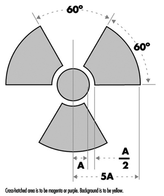
Areas controlled for the purposes of radiation safety are often designated in terms of increasing dose rate levels. Such areas must be conspicuously posted with a sign or signs bearing the radiation symbol and the words “CAUTION, RADIATION AREA,” “CAUTION (or DANGER), HIGH RADIATION AREA,” or “GRAVE DANGER, VERY HIGH RADIATION AREA,” as appropriate.
- A radiation area is an area, accessible to personnel, in which radiation levels could result in an individual receiving a dose equivalent in excess of 0.05 mSv in 1 h at 30 cm from the radiation source or from any surface that the radiation penetrates.
- A high radiation area is an area, accessible to personnel, in which radiation levels could result in an individual receiving a dose equivalent in excess of 1 mSv in 1 h at 30 cm from the radiation source or from any surface that the radiation penetrates.
- A very high radiation area is an area, accessible to personnel, in which radiation levels could result in an individual receiving an absorbed dose in excess of 5 Gy in 1 h at 1 m from a radiation source or from any surface that the radiation penetrates.
If an area or room contains a significant amount of radioactive material (as defined by the regulatory authority), the entrance to such area or room must be conspicuously posted with a sign bearing the radiation symbol and the words “CAUTION (or DANGER), RADIOACTIVE MATERIALS”.
An airborne radioactivity area is a room or area in which airborne radioactivity exceeds certain levels defined by the regulatory authority. Each airborne radioactivity area must be posted with a conspicuous sign or signs bearing the radiation symbol and the words “CAUTION, AIRBORNE RADIOACTIVITY AREA” or “DANGER, AIRBORNE RADIOACTIVITY AREA”.
Exceptions for these posting requirements may be granted for patients’ rooms in hospitals where such rooms are otherwise under adequate control. Areas or rooms in which the sources of radiation are to be located for periods of eight hours or less and are otherwise constantly attended under adequate control by qualified personnel need not be posted.
Access Control
The degree to which access to an area must be controlled is determined by the degree of the potential radiation hazard in the area.
Control of access to high radiation areas
Each entrance or access point to a high radiation area must have one or more of the following features:
- a control device that, upon entry into the area, causes the level of radiation to be reduced below that level at which an individual might receive a dose of 1 mSv in 1 h at 30 cm from the radiation source or from any surface that the radiation penetrates
- a control device that energizes a conspicuous visible or audible alarm signal so that the individual entering the high radiation area and the supervisor of the activity are made aware of the entry
- entryways that are locked, except during periods when access to the area is required, with positive control over each individual entry.
In place of the controls required for a high radiation area, continuous direct or electronic surveillance that is capable of preventing unauthorized entry may be substituted.
The controls must be established in a way that does not prevent individuals from leaving the high radiation area.
Control of access to very high radiation areas
In addition to the requirements for a high radiation area, additional measures must be instituted to ensure that an individual is not able to gain unauthorized or inadvertent access to areas in which radiation levels could be encountered at 5 Gy or more in 1 h at 1 m from a radiation source or any surface through which the radiation penetrates.
Markings on Containers and Equipment
Each container of radioactive material above an amount determined by the regulatory authority must bear a durable, clearly visible label bearing the radiation symbol and the words “CAUTION, RADIOACTIVE MATERIAL” or “DANGER, RADIOACTIVE MATERIAL”. The label must also provide sufficient information - such as the radionuclide(s) present, an estimate of the quantity of radioactivity, the date for which the activity is estimated, radiation levels, kinds of materials and mass enrichment - to permit individuals handling or using the containers, or working in the vicinity of the containers, to take precautions to avoid or minimize exposures.
Prior to removal or disposal of empty uncontaminated containers to unrestricted areas, the radioactive material label must be removed or defaced, or it must be clearly indicated that the container no longer contains radioactive materials.
Containers need not be labelled if:
- the containers are attended by an individual who takes the precautions necessary to prevent the exposure of individuals in excess of the regulatory limits
- containers, when they are in transport, are packaged and labelled in accordance with appropriate transportation regulations
- containers are accessible only to individuals authorized to handle or use them, or to work in the vicinity of the containers, if the contents are identified to these individuals by a readily available written record (examples of containers of this type are containers in locations such as water-filled canals, storage vaults or hot cells); the record must be retained as long as the containers are in use for the purpose indicated on the record; or
- the containers are installed in manufacturing or process equipment, such as reactor components, piping and tanks.
Warning Devices and Alarms
High radiation areas and very high radiation areas must be equipped with warning devices and alarms as discussed above. These devices and alarms can be visible or audible or both. Devices and alarms for systems such as particle accelerators should be automatically energized as part of the start-up procedure so that personnel will have time to vacate the area or turn off the system with a “scram” button before radiation is produced. “Scram” buttons (buttons in the controlled area that, when pressed, cause radiation levels to drop immediately to safe levels) must be easily accessible and prominently marked and displayed.
Monitor devices, such as continuous air monitors (CAMs), can be preset to emit audible and visible alarms or to turn off a system when certain action levels are exceeded.
Instrumentation
The employer must make available instrumentation appropriate for the degree and kinds of radiation and radioactive material present in the workplace. This instrumentation may be used to detect, monitor or measure the levels of radiation or radioactivity.
The instrumentation must be calibrated at appropriate intervals using accredited methods and calibration sources. The calibration sources should be as much as possible like the sources to be detected or measured.
Types of instrumentation include hand-held survey instruments, continuous air monitors, hand-and-feet portal monitors, liquid scintillation counters, detectors containing Ge or NaI crystals and so on.
Radioactive Material Transportation
The International Atomic Energy Agency (IAEA) has established regulations for the transportation of radioactive material. Most countries have adopted regulations compatible with IAEA radioactive shipment regulations.
Figure 2. Category I - WHITE label
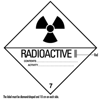
Figure 2, figure 3 and figure 4 are examples of shipping labels that IAEA regulations require on the exterior of packages presented for shipment that contain radioactive materials. The transport index on the labels shown in figure 3 and figure 4 refer to the highest effective dose rate at 1 m from any surface of the package in mSv/h multiplied by 100, then rounded up to the nearest tenth. (For example, if the highest effective dose rate at 1 m from any surface of a package is 0.0233 mSv/h, then the transport index is 2.4.)
Figure 3. Category II - YELLOW label
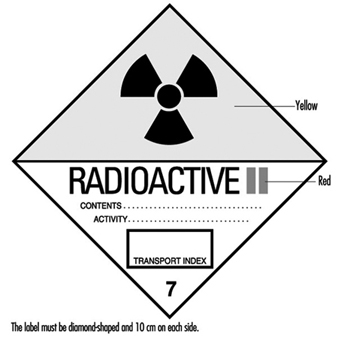
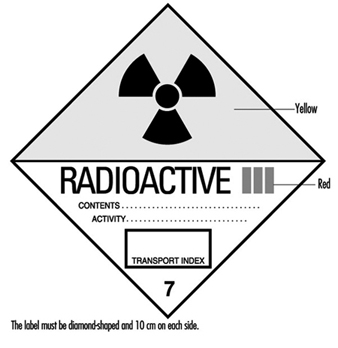
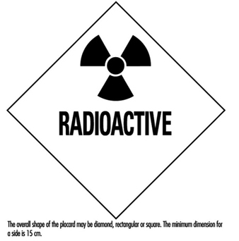
Figure 5 shows an example of a placard that ground vehicles must prominently display when carrying packages containing radioactive materials above certain amounts.
Figure 5. Vehicle placard
Packaging intended for use in shipping radioactive materials must comply with stringent testing and documentation requirements. The type and quantity of radioactive material being shipped determines what specifications the packaging must meet.
Radioactive material transportation regulations are complicated. Persons who do not routinely ship radioactive materials should always consult experts experienced with such shipments.
Radioactive Waste
Various radioactive waste disposal methods are available, but all are controlled by regulatory authorities. Therefore, an organization must always confer with its regulatory authority to ensure that a disposal method is permissible. Radioactive waste disposal methods include holding the material for radioactive decay and subsequent disposal without regard to radioactivity, incineration, disposal in the sanitary sewerage system, land burial and burial at sea. Burial at sea is often not permitted by national policy or international treaty and will not be discussed further.
Radioactive waste from reactor cores (high-level radioactive waste) presents special problems with regard to disposal. Handling and disposal of such wastes is controlled by national and international regulatory authorities.
Often radioactive waste may have a property other than radioactivity that by itself would make the waste hazardous. Such wastes are called mixed wastes. Examples include radioactive waste that is also a biohazard or is toxic. Mixed wastes require special handling. Refer to regulatory authorities for proper disposition of such wastes.
Holding for radioactive decay
If the half-life of the radioactive material is short (generally less than 65 days) and if the organization has enough storage space, the radioactive waste can be held for decay with subsequent disposal without regard to its radioactivity. A holding period of at least ten half-lives usually is sufficient to make radiation levels indistinguishable from background.
The waste must be surveyed before it may be disposed of. The survey should employ instrumentation appropriate for the radiation to be detected and demonstrate that radiation levels are indistinguishable from background.
Incineration
If the regulatory authority allows incineration, then usually it must be demonstrated that such incineration does not cause the concentration of radionuclides in air to exceed permissible levels. The ash must be surveyed periodically to verify that it is not radioactive. In some circumstances it may be necessary to monitor the stack to ensure that permissible air concentrations are not being exceeded.
Disposal in the sanitary sewerage system
If the regulatory authority allows such disposal, then usually it must be demonstrated that such disposal does not cause the concentration of radionuclides in water to exceed permissible levels. Material to be disposed of must be soluble or otherwise readily dispersible in water. The regulatory authority often sets specific annual limits to such disposal by radionuclide.
Land burial
Radioactive waste not disposable by any other means will be disposed of by land burial at sites licensed by national or local regulatory authorities. Regulatory authorities control such disposal tightly. Waste generators usually are not allowed to dispose of radioactive waste on their own land. Costs associated with land burial include packaging, shipping and storage expenses. These costs are in addition to the cost of the burial space itself and can often be reduced by compacting the waste. Land burial costs for radioactive waste disposal are rapidly escalating.
Programme Audits
Radiation safety programmes should be audited periodically for effectiveness, completeness and compliance with regulatory authority. The audit should be done at least once a year and be comprehensive. Self-audits are usually permissible but audits by independent outside agencies are desirable. Outside agency audits tend to be more objective and have a more global point of view than local audits. An auditing agency not associated with day-to-day operations of a radiation safety programme often can identify problems not seen by the local operators, who may have become accustomed to overlooking them.
Training
Employers must provide radiation safety training to all workers exposed or potentially exposed to ionizing radiation or radioactive materials. They must provide initial training before a worker begins work and annual refresher training. In addition, each female worker of child-bearing age must be provided special training and information about the effects of ionizing radiation on the unborn child and about appropriate precautions she should take. This special training must be given when she is first employed, at annual refresher training, and if she notifies her employer that she is pregnant.
All individuals working in or frequenting any portion of an area access to which is restricted for the purposes of radiation safety:
- must be kept informed of the storage, transfer or use of radioactive materials or of radiation in such portions of the restricted area
- must be instructed in the health protection problems associated with exposure to such radioactive materials or radiation, in precautions or procedures to minimize exposure, and in the purposes and functions of protective devices employed
- must be instructed in, and instructed to observe, to the extent within the worker’s control, the applicable provisions of national and employer regulations for the protection of personnel from exposures to radiation or radioactive materials occurring in such areas
- must be instructed of their responsibility to report promptly to the employer any condition which may lead to or cause a violation of national or employer regulations or unnecessary exposure to radiation or to radioactive material
- must be instructed in the appropriate response to warnings made in the event of any unusual occurrence or malfunction that may involve exposure to radiation or radioactive material
- must be advised as to the radiation exposure reports that workers may request.
The extent of radiation safety instructions must be commensurate with potential radiological health protection problems in the controlled area. Instructions must be extended as appropriate to ancillary personnel, such as nurses who attend radioactive patients in hospitals and fire-fighters and police officers who might respond to emergencies.
Worker Qualifications
Employers must ensure that workers using ionizing radiation are qualified to perform the work for which they are employed. The workers must have the background and experience to perform their jobs safely, particularly with reference to exposure to and use of ionizing radiation and radioactive materials.
Radiation safety personnel must have the appropriate knowledge and qualifications to implement and operate a good radiation safety programme. Their knowledge and qualifications must be at least commensurate with the potential radiological health protection problems that they and the workers are reasonably likely to encounter.
Emergency Planning
All but the smallest operations that use ionizing radiation or radioactive materials must have emergency plans in place. These plans must be kept current and exercised on a periodic basis.
Emergency plans should address all credible emergency situations. The plans for a large nuclear power plant will be much more extensive and involve a much larger area and number of people than the plans for a small radioisotope laboratory.
All hospitals, especially in large metropolitan areas, should have plans for receiving and caring for radioactively contaminated patients. Police and fire-fighting organizations should have plans for dealing with transportation accidents involving radioactive material.
Record Keeping
The radiation safety activities of an organization must be fully documented and appropriately retained. Such records are essential if the need arises for past radiation exposures or radioactivity releases and for demonstrating compliance with regulatory authority requirements. Consistent, accurate and comprehensive record keeping must receive high priority.
Organizational Considerations
The position of the person primarily responsible for radiation safety must be placed in the organization so that he or she has immediate access to all echelons of workers and management. He or she must have free access to areas to which access is restricted for purposes of radiation safety and the authority to halt unsafe or illegal practices immediately.
Planning for and Management of Radiation Accidents
This article describes several significant radiation accidents, their causes and the responses to them. A review of the events leading up to, during and following these accidents can provide planners with information to preclude future occurrences of such accidents and to enhance an appropriate, rapid response in the event a similar accident occurs again.
Acute Radiation Death Resulting from an Accidental Nuclear Critical Excursion on 30 December 1958
This report is noteworthy because it involved the largest accidental dose of radiation received by humans (to date) and because of the extremely professional and thorough work-up of the case. This represents one of the best, if not the best, documented acute radiation syndrome descriptions that exists (JOM 1961).
At 4:35 p.m. on 30 December 1958, an accidental critical excursion resulting in fatal radiation injury to an employee (K) took place in the plutonium recovery plant at the Los Alamos National Laboratory (New Mexico, United States).
The time of the accident is important because six other workers had been in the same room with K thirty minutes earlier. The date of the accident is important because the normal flow of fissionable material into the system was interrupted for year-end physical inventory. This interruption caused a routine procedure to become non-routine and led to an accidental “criticality” of the plutonium-rich solids that were accidentally introduced into the system.
Summary of estimates of K’s radiation exposure
The best estimate of K’s average total-body exposure was between 39 and 49 Gy, of which about 9 Gy was due to fission neutrons. A considerably greater portion of the dose was delivered to the upper half of the body than to the lower half. Table 1 shows an estimate of K’s radiation exposure.
Table 1. Estimates of K’s radiation exposure
|
Region and conditions |
Fast neutron |
Gamma |
Total |
|
Head (incident) |
26 |
78 |
104 |
|
Upper abdomen |
30 |
90 |
124 |
|
Total body (average) |
9 |
30-40 |
39-49 |
Clinical course of patient
In retrospect, the clinical course of patient K can be divided into four distinct periods. These periods differed in duration, symptoms and response to supportive therapy.
The first period, lasting from 20 to 30 minutes, was characterized by his immediate physical collapse and mental incapacitation. His condition progressed to semi-consciousness and severe prostration.
The second period lasted about 1.5 hours and began with his arrival by stretcher at the emergency room of the hospital and ended with his transfer from the emergency room to the ward for further supportive therapy. This interval was characterized by such severe cardiovascular shock that death seemed imminent during the whole time. He seemed to be suffering severe abdominal pain.
The third period was about 28 hours long and was characterized by enough subjective improvement to encourage continued attempts to alleviate his anoxia, hypotension and circulatory failure.
The fourth period began with the unheralded onset of rapidly increasing irritability and antagonism, bordering on mania, followed by coma and death in approximately 2 hours. The entire clinical course lasted 35 hours from the time of radiation exposure to death.
The most dramatic clinicopathological changes were observed in the haemopoietic and urinary systems. Lymphocytes were not found in the circulating blood after the eighth hour, and there was virtually complete urinary shutdown despite administration of large amount of fluids.
K’s rectal temperature varied between 39.4 and 39.7°C for the first 6 hours and then fell precipitously to normal, where it remained for the duration of his life. This high initial temperature and its maintenance for 6 hours were considered in keeping with his suspected massive dose of radiation. His prognosis was grave.
Of all the various determinations made during the course of the illness, changes in white cell count were found to be the simplest and best prognostic indicator of severe irradiation. The virtual disappearance of lymphocytes from the peripheral circulation within 6 hours of exposure was considered a grave sign.
Sixteen different therapeutic agents were employed in the symptomatic treatment of K over about a 30-hour period. In spite of this and continued oxygen administration, his heart tones became very distant, slow and irregular about 32 hours after irradiation. His heart then became progressively weaker and suddenly stopped 34 hours 45 minutes after irradiation.
Windscale Reactor No. 1 Accident of 9-12 October 1957
Windscale reactor No. 1 was an air-cooled, graphite-moderated natural uranium-fuelled plutonium production reactor. The core was partially ruined by fire on 15 October 1957. This fire resulted in a release of approximately 0.74 PBq (10+15 Bq) of iodine-131 (131I) to the downwind environment.
According to a US Atomic Energy Commission accident information report about the Windscale incident, the accident was caused by operator judgement errors concerning thermocouple data and was made worse by faulty handling of the reactor that permitted the graphite temperature to rise too rapidly. Also contributory was the fact that fuel temperature thermocouples were located in the hottest part of the reactor (that is, where the highest dose rates occurred) during normal operations rather than in parts of the reactor which were hottest during an abnormal release. A second equipment deficiency was the reactor power meter, which was calibrated for normal operations and read low during the annealing. As a result of the second heating cycle, the graphite temperature rose on 9 October, especially in the lower front part of the reactor where some cladding had failed because of the earlier rapid temperature rise. Although there were a number of small iodine releases on 9 October, the releases were not recognized until 10 October when the stack activity meter showed a significant increase (which was not regarded as highly significant). Finally, on the afternoon of 10 October, other monitoring (Calder site) indicated the release of radioactivity. Efforts to cool the reactor by forcing air through it not only failed but actually increased the magnitude of the radioactivity released.
The estimated releases from the Windscale accident were 0.74 PBq of 131I, 0.22 PBq of caesium-137 (137Cs), 3.0 TBq (1012Bq) of strontium-89 (89Sr), and 0.33 TBq of strontium-90
(90Sr). The highest offsite gamma absorbed dose rate was about 35 μGy/h due to airborne activity. Air activity readings around the Windscale and Calder plants often were 5 to 10 times the maximum permissible levels, with occasional peaks of 150 times permissible levels. A milk ban extended over a radius of approximately 420 km.
During operations to bring the reactor under control, 14 workers received dose equivalents greater than 30 mSv per calendar quarter, with the maximum dose equivalent at 46 mSv per calendar quarter.
Lessons learned
There were many lessons learned concerning natural uranium reactor design and operation. The inadequacies concerning reactor instrumentation and reactor operator training also bring up points analogous to the Three Mile Island accident (see below).
No guidelines existed for short-term permissible exposure to radioiodine in food. The British Medical Research Council performed a prompt and thorough investigation and analysis. Much ingenuity was used in promptly deriving maximum permissible concentrations for 131I in food. The study Emergency Reference Levels that resulted from this accident serves as a basis for emergency planning guides now used worldwide (Bryant 1969).
A useful correlation was derived for predicting significant radioiodine contamination in milk. It was found that gamma radiation levels in pastures which exceeded 0.3 μGy/h yielded milk which exceeded 3.7 MBq/m3.
Absorbed dose from inhalation of external exposure to radioiodines is negligible compared to that from drinking milk or eating dairy products. In an emergency, rapid gamma spectroscopy is preferable to slower laboratory procedures.
Fifteen two-person teams performed radiation surveys and obtained samples. Twenty persons were used for sample coordination and data reporting. About 150 radiochemists were involved in sampling analysis.
Glass wool stack filters are not satisfactory under accident conditions.
Gulf Oil Accelerator Accident of 4 October 1967
Gulf Oil Company technicians were using a 3 MeV Van de Graaff accelerator for the activation of soil samples on 4 October 1967. The combination of an interlock failure on the power key of the accelerator console and the taping of several of the interlocks on the safety tunnel door and the target room inside door produced serious accidental exposures to three individuals. One individual received approximately 1 Gy whole-body dose equivalent, the second received close to 3 Gy whole-body dose equivalent and the third received approximately 6 Gy whole-body dose equivalent, in addition to approximately 60 Gy to the hands and 30 Gy to the feet.
One of the accident victims reported to the medical department, complaining of nausea, vomiting and generalized muscular aches. His symptoms initially were misdiagnosed as flu symptoms. When the second patient came in with approximately the same symptoms, it was decided that they may possibly have received significant radiation exposures. Film badges verified this. Dr. Niel Wald, University of Pittsburgh Radiological Health Division, supervised the dosimetry tests and also acted as coordinating physician in the work-up and treatment of the patients.
Dr. Wald very quickly had absolute filter units flown in to the western Pennsylvania hospital in Pittsburgh where the three patients had been admitted. He set up these absolute filter/laminar flow filters to clean the patients’ environment of all biological contaminants. These “reverse isolation” units were used on the 1 Gy exposure patient for about 16 days, and on the 3 and 6 Gy exposure patients for about a month and half.
Dr. E. Donnal Thomas from the University of Washington arrived to perform a bone marrow transplant on the 6 Gy patient on the eighth day after exposure. The patient’s twin brother served as the bone marrow donor. Although this heroic medical treatment saved the 6 Gy patient’s life, nothing could be done to save his arms and legs, each of which received tens-of-gray absorbed dose.
Lessons learned
If the simple operating procedure of always using a survey meter when entering the exposure room had been followed, this tragic accident would have been avoided.
At least two interlocks had been taped closed for long periods of time prior to this accident. Defeating of protective interlocks is intolerable.
Regular maintenance checks should have been made on the key-operated power interlocks for the accelerator.
Timely medical attention saved the life of the person with the highest exposure. The heroic procedure of a complete bone marrow transplant together with the use of reverse isolation and quality medical care were all major factors in saving this person’s life.
Reverse isolation filters can be obtained in a matter of hours to be set up in any hospital to care for highly exposed patients.
In retrospect, medical authorities involved with these patients would have recommended amputation earlier and at a definitive level within two or three months after the exposure. Earlier amputation decreases the likelihood of infection, gives a shorter period of severe pain, reduces pain medication required for the patient, possibly reduces the patient’s hospital stay, and possibly contributes to earlier rehabilitation. Earlier amputation should, of course, be done while correlating dosimetry information with clinical observations.
The SL–1 Prototype Reactor Accident (Idaho, USA, 3 January 1961)
This is the first (and to date the only) fatal accident in the history of US reactor operations. The SL-1 is a prototype of a small Army Package Power Reactor (APPR) designed for air transportation to remote areas for production of electrical power. This reactor was used for fuel testing, and for reactor crew training. It was operated in the remote desert location of the National Reactor Testing Station in Idaho Falls, Idaho, by Combustion Engineering for the US Army. The SL-1 was not a commercial power reactor (AEC 1961; American Nuclear Society 1961).
At the time of the accident, the SL-1 was loaded with 40 fuel elements and 5 control rod blades. It could produce a power level of 3 MW (thermal) and was a boiling water–cooled and –moderated reactor.
The accident resulted in the deaths of three military personnel. The accident was caused by the withdrawal of a single control rod for a distance of more than 1 m. This caused the reactor to go into prompt criticality. The reason why a skilled, licensed reactor operator with much refuelling operation experience withdrew the control rod past its normal stop point is unknown.
One of the three accident victims was still alive when initial response personnel first reached the scene of the accident. High activity fission products covered his body and were embedded in his skin. Portions of the victim’s skin registered in excess of 4.4 Gy/h at 15 cm and hampered rescue and medical treatment.
Lessons learned
No reactor designed since the SL-1 accident can be brought to “prompt-critical” state with a single control rod.
All reactors must have portable survey meters onsite that have ranges greater than 20 mGy/h. Survey meters of 10 Gy/h maximum range are recommended.
Note: The Three Mile Island accident showed that 100 Gy/h is the required range for both gamma and beta measurements.
Treatment facilities are required where a highly contaminated patient can receive definitive medical treatment with reasonable safeguards for attendant personnel. Since most of these facilities will be in clinics with other ongoing missions, control of airborne and waterborne radioactive contaminants may require special provisions.
X-ray Machines, Industrial and Analytical
Accidental exposures from x-ray systems are numerous and often involve extremely high exposures to small portions of the body. It is not unusual for x-ray diffraction systems to produce absorbed dose rates of 5 Gy/s at 10 cm from the tube focus. At shorter distances, 100 Gy/s rates have often been measured. The beam is usually narrow, but even a few seconds’ exposure can result in severe local injury (Lubenau et al. 1967; Lindell 1968; Haynie and Olsher 1981; ANSI 1977).
Because these systems are often used in “non-routine” circumstances, they lend themselves to the production of accidental exposures. X-ray systems commonly used in normal operations appear to be reasonably safe. Equipment failure has not caused severe exposures.
Lessons learned from accidental x-ray exposures
Most accidental exposures occurred during non-routine uses when equipment was partially disassembled or shield covers had been removed.
In most serious exposures, adequate instruction for the staff and maintenance personnel had been lacking.
If simple and fail-safe methods had been used to ensure that x-ray tubes were turned off during repairs and maintenance, many accidental exposures would have been avoided.
Finger or wrist personnel dosimeters should be used for operators and maintenance personnel working with these machines.
If interlocks had been required, many accidental exposures would have been avoided.
Operator error was a contributing cause in most of the accidents. Lack of adequate enclosures or poor shielding design often worsened the situation.
Industrial radiography accidents
From the 1950s through the 1970s, the highest radiation accident rate for a single activity has consistently been for industrial radiographic operations (IAEA 1969, 1977). National regulatory bodies continue to struggle to reduce the rate by a combination of improved regulations, strict training requirements and ever tougher inspection and enforcement policies (USCFR 1990). These regulatory efforts have generally succeeded, but many accidents associated with industrial radiography still occur. Legislation allowing huge monetary fines may be the most effective tool in keeping radiation safety focused in the minds of industrial radiography management (and also, therefore, in workers’ minds).
Causes of industrial radiography accidents
Worker training. Industrial radiography probably has lower education and training requirements than any other type of radiation employment. Therefore, existing training requirements must be strictly enforced.
Worker production incentive. For years, major emphasis for industrial radiographers was placed on the amount of successful radiographs produced per day. This practice can lead to unsafe acts as well as to occasional non-use of personnel dosimetry so that exceeding dose equivalent limits would not be detected.
Lack of proper surveys. Thorough surveying of source pigs (storage containers) (figure 1) after every exposure is most important. Not performing these surveys is the single most probable cause of unnecessary exposures, many of which are unrecorded, since industrial radiographers rarely use hand or finger dosimeters (figure 1).
Figure 1. Industrial radiography camera
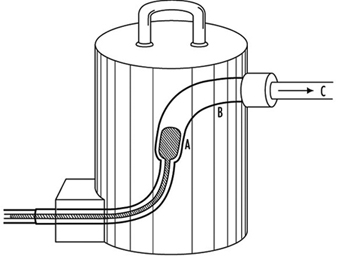
Equipment problems. Because of heavy use of industrial radiographic cameras, source winding mechanisms can loosen and cause the source to not completely retract into its safe storage position (point A in figure 1). There are also many instances of closet-source interlock failures that cause accidental exposures of personnel.
Design of Emergency Plans
Many excellent guidelines, both general and specific, exist for the design of emergency plans. Some references are particularly helpful. These are given in the suggested readings at the end of this chapter.
Initial drafting of emergency plan and procedures
First, one must assess the entire radioactive material inventory for the subject facility. Then credible accidents must be analysed so that one can determine the probable maximum source release terms. Next, the plan and its procedures must enable the facility operators to:
- recognize an accident situation
- classify the accident according to severity
- take steps to mitigate the accident
- make timely notifications
- call for help efficiently and quickly
- quantify releases
- keep track of exposures both on- and offsite, as well as keep emergency exposures ALARA
- recover the facility as quickly as practical
- keep accurate and detailed records.
Types of accidents associated with nuclear reactors
A list, from most likely to least likely, of types of accidents associated with nuclear reactors follows. (The non-nuclear reactor, general-industrial type accident is by far the most likely.)
- Low level unexpected release of radioactive material with little or no external radiation exposure to personnel. Usually occurs during major overhauls or in shipment of spent resin or spent fuel. Coolant system leakage and coolant-sample sink spills are often causes of spread of radioactive contamination.
- Unexpected external exposure of personnel. This usually occurs during major overhauls or routine maintenance.
- A combination of contamination spread, contamination of personnel, and low-level personnel external radiation exposure is the next most likely accident. These accidents occur under the same conditions as 1 and 2 above.
- Gross surface contamination due to a major reactor coolant system leak or a leak of spent fuel coolant.
- Chips or large particles of activated CRUD (see definition below) in or on skin, ears or eyes.
- High-level radiation exposure of plant personnel. This is usually caused by carelessness.
- Release of small but greater than permissible quantities of radioactive wastes to outside the plant boundary. This is usually associated with human failures.
- Meltdown of reactor. Gross contamination offsite plus high personnel exposure would probably occur.
- Reactor excursion (SL–1 type of accident).
Radionuclides expected from water-cooled reactor accidents:
- activated corrosion and erosion products (commonly known as CRUD) in the coolant; for example, cobalt-60 or -58 (60Co, 58Co), iron-59 (59Fe), manganese-58 (58Mn) and tantalum-183 (183Ta)
- low level fission products usually present in the coolant; for example, iodine-131 (131I) and caesium-137 (137Cs)
- in boiling water reactors, 1 and 2 above plus continuous off-gassing of low levels of tritium
- (3H) and noble radioactive gases such as xenon-133 and -135 (133Xe, 135Xe), argon-41 (41Ar), and krypton-85 (85Kr)
- tritium (3H) manufactured inside the core at the rate of 1.3 × 10⁻⁴ atoms of 3H per fission (only a fraction of this leaves the fuel).
Figure 2. Example of a nuclear power plant emergency plan, table of contents
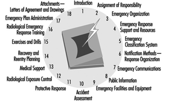
Typical Nuclear Power Plant Emergency Plan, Table of Contents
Figure 2 is an example of a table of contents for a nuclear power plant emergency plan. Such a plan should include each chapter shown and be tailored to meet local requirements. A list of typical power reactor implementation procedures is given in figure 3.
Figure 3. Typical power reactor implementation procedures
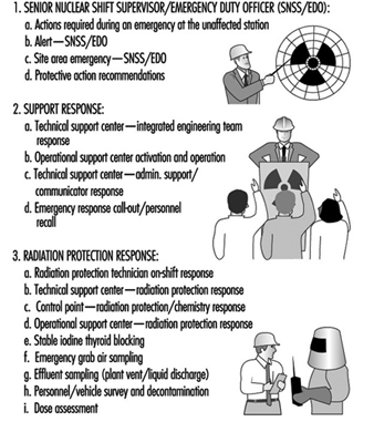
Radiological Environmental Monitoring during Accidents
This task is often called EREMP (Emergency Radiological Environmental Monitoring Programme) at large facilities.
One of the most important lessons learned for the US Nuclear Regulatory Commission and other government agencies from the Three Mile Island accident was that one cannot successfully implement EREMP in one or two days without extensive prior planning. Although the US government spent many millions of dollars monitoring the environment around the Three Mile Island nuclear station during the accident, less then 5% of the total releases were measured. This was due to poor and inadequate prior planning.
Designing Emergency Radiological Environmental Monitoring Programmes
Experience has shown that the only successful EREMP is one that is designed into the routine radiological environmental monitoring programme. During the early days of the Three Mile Island accident, it was learned that an effective EREMP cannot be established successfully in a day or two, no matter how much manpower and money are applied to the programme.
Sampling locations
All routine radiological environmental monitoring programme locations will be used during long-term accident monitoring. In addition, a number of new locations must be set up so that motorized survey teams have pre-determined locations in each portion of each 22½° sector (see figure 3). Generally, sampling locations will be in areas with roads. However, exceptions must be made for normally inaccessible but potentially occupied sites such as camp grounds and hiking trails within about 16 km downwind of the accident.
Figure 3. Sector and zone designations for radiological sampling and monitoring points within emergency planning zones
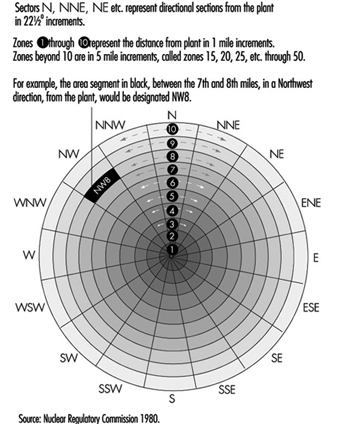
Figure 3 shows the sector and zone designation for radiation and environmental monitoring points. One may designate 22½° sectors by cardinal directions (for example, N, NNE, and NE) or by simple letters (for example, A through R). However, use of letters is not recommended because they are easily confused with directional notation. For example, it is less confusing to use the directional W for west rather than the letter N.
Each designated sample location should be visited during a practice drill so that people responsible for monitoring and sampling will be familiar with the location of each point and will be aware of radio “dead spaces,” poor roads, problems with finding the locations in the dark and so on. Since no drill will cover all the pre-designated locations within the 16 km emergency protection zone, drills must be designed so that all sample points will be visited eventually. It is often worthwhile to predetermine the ability of survey team vehicles to communicate with each pre-designated point. The actual locations of the sample points are chosen utilizing the same criteria as in the REMP (NRC 1980); for example, line of site, minimum exclusion area, closest individual, closest community, closest school, hospital, nursing home, milch animal herd, garden, farm and so on.
Radiological monitoring survey team
During an accident involving significant releases of radioactive materials, radiological monitoring teams should be continuously monitoring in the field. They also should continuously monitor onsite if conditions allow. Normally, these teams will monitor for ambient gamma and beta radiation and sample air for the presence of radioactive particulates and halogens.
These teams must be well trained in all monitoring procedures, including monitoring their own exposures, and be able to accurately relay these data to the base station. Details such as survey-meter type, serial number, and open-or closed-window status must be carefully reported on well-designed log sheets.
At the beginning of an emergency, an emergency monitoring team may have to monitor for 12 hours without a break. After the initial period, however, field time for the survey team should be decreased to eight hours with at least one 30 minute break.
Since continuous surveillance may be needed, procedures must be in place to supply the survey teams with food and drink, replacement instruments and batteries, and for back-and-forth transfer of air filters.
Even though survey teams will probably be working 12 hours per shift, three shifts a day are needed to provide continuous surveillance. During the Three Mile Island accident, a minimum of five monitoring teams was deployed at any one time for the first two weeks. The logistics for supporting such an effort must be carefully planned in advance.
Radiological environmental sampling team
The types of environmental samples taken during an accident depend on the type of releases (airborne versus water), direction of the wind and time of year. Soil and drinking water samples must be taken even in winter. Although radio-halogen releases may not be detected, milk samples should be taken because of the large bioaccumulation factor.
Many food and environmental samples must be taken to reassure the public even though technical reasons may not justify the effort. In addition, these data may be invaluable during any subsequent legal proceedings.
Pre-planned log sheets using carefully thought out offsite data procedures are essential for environmental samples. All persons taking environmental samples should have demonstrated a clear understanding of procedures and have documented field training.
If possible, offsite environmental sample data collection should be done by an independent offsite group. It is also preferable that routine environmental samples be taken by the same offsite group, so that the valuable onsite group may be used for other data collection during an accident.
It is notable that during the Three Mile Island accident every single environmental sample that should have been taken was collected, and not one environmental sample was lost. This occurred even though the sampling rate increased by a factor of more than ten over pre-accident sampling rates.
Emergency monitoring equipment
The inventory of emergency monitoring equipment should be at least double that needed at any given time. Lockers should be placed around nuclear complexes in various places so that no one accident will deny access to all of these lockers. To ensure readiness, equipment should be inventoried and its calibration checked at least twice a year and after each drill. Vans and trucks at large nuclear facilities should be completely outfitted for both on and offsite emergency surveillance.
Onsite counting laboratories may be unusable during an emergency. Therefore, prior arrangements must be made for an alternate or a mobile counting laboratory. This is now a requirement for US nuclear power plants (USNRC 1983).
The type and sophistication of environmental monitoring equipment should meet the requirements of attending the nuclear facility’s worst credible accident. Following is a list of typical environmental monitoring equipment required for nuclear power plants:
- Air sampling equipment should include units which are battery operated for short-term sampling and AC operable with strip chart recorders and alarm capabilities for longer-term surveillance.
- Liquid sampling equipment should contain continuous samplers. The samplers must be operable in the local environment, no matter how harsh it is.
- Portable gamma survey meters for implant work should have a maximum range of 100 Gy/h, and separate survey equipment should be able to measure beta radiation up to 100 Gy/h.
- Onsite, personnel dosimetry must include beta measurement capability, as well as finger thermoluminescent dosimeters (TLDs) (figure 4). Other extremity dosimetry also may be needed. Extra sets of control dosimeters are always needed in emergencies. A portable TLD reader may be needed to link with the station computer via telephone modem in emergency locations. In-house survey teams, such as rescue and repair teams, should have low- and high-range pocket dosimeters as well as pre-set alarm dosimeters. Careful thought must be given to pre-established dose levels for teams that may be in high radiation areas.
- Supplies of protective clothing should be supplied in emergency locations and in emergency vehicles. Extra back-up protective clothing should be available in case of accidents lasting for an extended period of time.
- Respiratory protection equipment should be in all emergency lockers and vehicles. Up-to-date lists of respiratory trained personnel should be kept in each of the major emergency equipment storage areas.
- Mobile vehicles equipped with radios are essential for emergency radiation monitoring survey teams. The location and availability of back-up vehicles must be known.
- Environmental survey team equipment should be stored in a convenient place, preferably offsite, so that it is always available.
- Emergency kits should be placed in the Technical Support Center and the Emergency Offsite Facility so that replacement survey teams need not go onsite in order to receive equipment and be deployed.
- For a severe accident involving the release of radioactive materials into the air, preparations must be in place for the use of helicopters and single-engine airplanes for airborne surveillance.
Figure 4. An industrial radiographer wearing a TLD badge and a ring thermoluminescent dosimeter (optional in the US)

Data analysis
Environmental data analysis during a serious accident should be shifted as soon as possible to an offsite location such as the Emergency Offsite Facility.
Pre-set guidelines about when environmental sample data are to be reported to management must be established. The method and frequency for transfer of environmental sample data to governmental agencies should be agreed upon early in the accident.
Health Physics and Radiochemistry Lessons Learned from the Three Mile Island Accident
Outside consultants were needed to perform the following activities because plant health physicists were fully occupied by other duties during the early hours of the 28 March 1979 Three Mile Island accident:
- radioactive effluent release assessment (gaseous and liquid), including sample collection, coordination of laboratories for sample counting, quality control of laboratories, data collection, data analysis, report generation, distribution of data to government agencies and power plant owner
- dose assessment, including suspected and actual overexposure investigations, skin contamination and internal deposition investigations, significant exposure mock-ups, and dose calculations
- radiological environmental monitoring programme, including complete coordination of sample taking, data analysis, report generation and distribution, action-point notifications, expansion of programme for the accident situation and then contraction of the programme for up to one year after the accident
- special beta dosimetry studies, including studies of the state of the art in beta personnel monitoring, modelling of the beta dose to skin from radioactive contaminants, inter-comparisons of all commercially available beta-gamma TLD personnel dosimetry systems.
The above list includes examples of activities that the typical utility health physics staff cannot adequately accomplish during a serious accident. The Three Mile Island health physics staff was very experienced, knowledgeable and competent. They worked 15 to 20 hours per day for the first two weeks of the accident without a break. Yet, additional requirements caused by the accident were so numerous that they were unable to perform many important routine tasks that ordinarily would be performed easily.
Lessons learned from the Three Mile Island accident include:
Auxiliary building entry during accident
- All entries must be on a new radiation work permit reviewed by the senior health physicist onsite and signed by the unit superintendent or designated alternate.
- The appropriate control room should have absolute control over all Auxiliary and Fuel Handling Building entries. No entries must be allowed unless a health physicist is at the control point during the entry.
- No entries without a properly operating survey meter of appropriate range should be allowed. A spot check of meter response should be performed immediately prior to entry.
- Exposure history for all persons prior to their entry into a high radiation area must be obtained.
- Allowable exposures during entry, no matter how important the task should be designated.
Primary coolant sampling during accident
- All samples to be taken on a new radiation work permit should be reviewed by the senior health physicist onsite and signed by the unit superintendent or alternate.
- No coolant samples should be taken unless an extremity dosimeter is worn.
- No coolant samples should be taken without the availability of shielded gloves and tongs at least 60 cm long in case a sample is more radioactive than expected.
- No coolant samples should be taken without a leaded-glass personnel shield in place in case a sample is more radioactive than expected.
- Sample-taking should be discontinued if the exposure to an extremity or to the whole-body is likely to exceed pre-set levels stated on the radiation work permit.
- Significant exposures should be distributed among a number of workers if possible.
- All cases of skin contamination in excess of action levels within 24 hours should be reviewed.
Make-up valve room entry
- Beta and gamma area surveys using remote detectors with appropriate maximum range must be performed.
- Initial entry in an area with an absorbed dose rate of more than 20 mGy/h must have prior review to verify that exposure to radiation will be kept as low as reasonably achievable.
- When water leaks are suspected, possible floor contamination should be detected.
- A consistent programme for type and placement of personnel dosimetry must be put into operation.
- With persons entering an area with an absorbed dose rate of more than 20 mGy/h, TLDs must be assessed immediately after exit.
- It should be verified that all radiation work permit requirements are being carried out prior to entry into an area with an absorbed dose rate of more than 20 mGy/h.
- Controlled-time entries into hazardous areas must be timed by a health physicist.
Protective actions and offsite environmental surveillance from the local government’s perspective
- Before beginning a sampling protocol, criteria for stopping it should be established.
- Outside interference should not be allowed.
- Several confidential telephone lines should be in place. The numbers should be changed after each crisis.
- The capabilities of aerial measuring systems are better than most people think they are.
- A tape recorder should be in hand and data recorded regularly.
- While the acute episode is in progress, the reading of newspapers, watching television and listening to the radio should be abandoned as these activities only add to existing tensions.
- Food delivery and other comforts such as sleeping facilities should be planned for as it may be impossible to go home for a while.
- Alternate analytic capabilities should be planned for. Even a small accident can alter laboratory background radiation levels significantly.
- It should be noted that more energy will be expended in heading off unsound decisions than in dealing with real problems.
- It should be understood that emergencies cannot be managed from remote locations.
- It should be noted that protective action recommendations are not amenable to committee vote.
- All non-essential calls should be put on hold, time-wasters are to be hung up on.
The Goiânia Radiological Accident of 1985
A 51 TBq 137Cs teletherapy unit was stolen from an abandoned clinic in Goiânia, Brazil, on or around 13 September 1985. Two people looking for scrap metal took home the source assembly of the teletherapy unit and attempted to disassemble the parts. The absorbed dose rate from the source assembly was about 46 Gy/h at 1 m. They did not understand the meaning of the three-bladed radiation symbol on the source capsule.
The source capsule ruptured during disassembly. Highly soluble caesium-137 chloride (137CsCl) powder was disbursed throughout a part of this city of 1,000,000 people and caused one of the most serious sealed source accidents in history.
After the disassembly, remnants of the source assembly were sold to a junk dealer. He discovered that the 137CsCl powder glowed in the dark with a blue colour (presumably, this was Cerenkov radiation). He thought that the powder could be a gemstone or even supernatural. Many friends and relatives came to see the “wonderful” glow. Portions of the source were given to a number of families. This process continued for about five days. By this time a number of people had developed gastro-intestinal syndrome symptoms from radiation exposure.
Patients who went to the hospital with severe gastro-intestinal disorders were misdiagnosed as having allergic reactions to something they ate. A patient who had severe skin effects from handling the source was suspected of having some tropical skin disease and was sent to the Tropical Disease Hospital.
This tragic sequence of events continued undetected by knowledgeable personnel for about two weeks. Many people rubbed the 137CsCl powder on their skins so that they could glow blue. The sequence might have continued much longer except that one of the irradiated persons finally connected the illnesses with the source capsule. She took the remnants of the 137CsCl source on a bus to the Public Health Department in Goiânia where she left it. A visiting medical physicist surveyed the source the next day. He took actions on his own initiative to evacuate two junkyard areas and to inform authorities. The speed and overall size of response of the Brazilian government, once it became aware of the accident, were impressive.
About 249 people were contaminated. Fifty-four were hospitalized. Four people died, one of whom was a six-year-old girl who received an internal dose of about 4 Gy from ingesting about 1 GBq (109 Bq) of 137Cs.
Response to the accident
The objectives of the initial response phase were to:
- identify the main sites of contamination
- evacuate residences where levels of radioactivity exceeded the intervention levels adopted
- establish health physics controls around these areas, preventing access where necessary
- identify persons who had incurred significant doses or were contaminated.
The medical team initially:
- upon its arrival in Goiânia, took histories and triaged according to acute radiation syndrome symptoms
- sent all acute radiation patients to Goiânia Hospital (which was set up in advance for contamination and exposure control)
- transferred by air the next day the six most critical patients to the tertiary care center at a naval hospital in Rio de Janeiro (later eight more patients were transferred to this hospital)
- made arrangements for cytogenetic radiation dosimetry
- based medical management on each patient on that patient’s clinical course
- gave informal instruction to clinical laboratory staff to diminish their fears (the Goiânia medical community was reluctant to help).
Health physicists:
- assisted physicians in radiation dosimetry, bioassay and skin decontamination
- coordinated and interpreted analysis of 4,000 urine and faecal samples in a four-month period
- whole-body counted 600 individuals
- coordinated radio-contamination monitoring of 112,000 individuals (249 were contaminated)
- performed aerial survey of entire city and suburbs utilizing hastily assembled NaI detectors
- performed auto-mounted NaI detector surveys of over 2,000 km of roads
- set up action levels for decontamination of people, buildings, autos, soil and so on
- coordinated 550 workers employed in decontamination efforts
- coordinated demolition of seven houses and decontamination of 85 houses
- coordinated hauling of 275 truckloads of contaminated waste
- coordinated decontamination of 50 vehicles
- coordinated packaging of 3,500 cubic metres of contaminated waste
- utilized 55 survey meters, 23 contamination monitors and 450 self-reading dosimeters.
Results
Acute radiation syndrome patients
Four patients died as a result of absorbed doses ranging from 4 to 6 Gy. Two patients exhibited severe bone marrow depression, but lived in spite of absorbed doses of 6.2 and 7.1 Gy (cytogenetic estimate). Four patients survived with estimated absorbed doses from 2.5 to 4 Gy.
Radiation-induced skin injury
Nineteen of twenty hospitalized patients had radiation-induced skin injuries, which started with swelling and blistering. These lesions later ruptured and secreted fluid. Ten of the nineteen skin injuries developed deep lesions about four to five weeks after irradiation. These deep lesions were indicative of significant gamma exposure of deeper tissues.
All skin lesions were contaminated with 137Cs, with absorbed dose rates up to 15 mGy/h.
The six-year-old girl who ingested 1 TBq of 137Cs (and who died one month later) had generalized skin contamination that averaged 3 mGy/h.
One patient required an amputation about a month after exposure. Blood-pool imaging was useful in determining the demarcation between injured and normal arterioles.
Internal contamination result
Statistical tests showed no significant differences between body burdens determined by whole body counting as opposed to those determined by urinary excretion data.
Models that related bioassay data with intakes and body burden were validated. These models were also applicable for different age groups.
Prussian Blue was useful in promoting the elimination of 137CsCl from the body (if dosage was greater than 3 Gy/d).
Seventeen patients received diuretics for the elimination of 137CsCl body burdens. These diuretics were ineffective in de-corporating 137Cs and their use was stopped.
Skin decontamination
Skin decontamination using soap and water, acetic acid, and titanium dioxide (TiO2) was performed on all patients. This decontamination was only partly successful. It was surmised that sweating resulted in recontaminating the skin from the 137Cs body burden.
Contaminated skin lesions are very difficult to decontaminate. Sloughing of necrotic skin significantly reduced contamination levels.
Follow-up study on cytogenetic analysis dose assessment
Frequency of aberrations in lymphocytes at different times after the accident followed three main patterns:
In two cases the frequencies of incidence of aberrations remained constant up to one month after the accident and declined to about 30% of the initial frequency three months later.
In two cases a gradual decrease of about 20% every three months was found.
In two of the cases of highest internal contamination there were increases in the frequency of incidence of aberrations (by about 50% and 100%) over a three-month period.
Follow-up studies on 137Cs body burdens
- Patients’ actual committed doses followed by bioassay.
- Effects of Prussian Blue administration followed.
- In vivo measurements for 20 people made on blood samples, wounds and organs to look for non-homogenous distribution of 137Cs and its retention in body tissues.
- A woman and her newborn baby studied to look for retention and transfer by nursing.
Action levels for intervention
House evacuation was recommended for absorbed dose rates greater than 10 μGy/h at 1 m height inside the house.
Remedial decontamination of property, clothing, soil and food was based on a person not exceeding 5 mGy in a year. Applying this criterion for different pathways resulted in decontaminating the inside of a house if the absorbed dose could exceed 1 mGy in a year and decontaminating soil if the absorbed dose rate could exceed 4 mGy in a year (3 mGy from external radiation and 1 mGy from internal radiation).
The Chernobyl Nuclear Power Reactor Unit 4 Accident of 1986
General description of the accident
The world’s worst nuclear power reactor accident occurred on 26 April 1986 during a very low-powered electrical engineering test. In order to perform this test, a number of safety systems were switched off or blocked.
This unit was a model RBMK-1000, the type of reactor that produced about 65% of all nuclear power generated in the USSR. It was a graphite-moderated, boiling-water reactor that generated 1,000 MW of electricity (MWe). The RBMK-1000 does not have a pressure-tested containment building and is not commonly built in most countries.
The reactor went prompt critical and produced a series of steam explosions. The explosions blew off the entire top of the reactor, destroyed the thin structure covering the reactor, and started a series of fires on the thick asphalt roofs of units 3 and 4. Radioactive releases lasted for ten days, and 31 people died. The USSR delegation to the International Atomic Energy Agency studied the accident. They stated that the Chernobyl Unit 4 RBMK experiments that caused the accident had not received required approval and that the written rules on reactor safety measures were inadequate. The delegation further stated, “The staff involved were not adequately prepared for the tests and were not aware of the possible dangers.” This series of tests created the conditions for the emergency situation and led to a reactor accident which most believed could never occur.
Release of Chernobyl Unit 4 accident fission products
Total activity released
Roughly 1,900 PBq of fission products and fuel (which together were labelled corium by the Three Mile Island Accident Recovery Team) were released over the ten days that it took to put out all the fires and seal off Unit 4 with a neutron absorbing shielding material. Unit 4 is now a permanently sealed steel and concrete sarcophagus that properly contains the residual corium in and around the remains of the destroyed reactor core.
Twenty-five per cent of the 1,900 PBq was released on the first day of the accident. The rest was released during the next nine days.
The most radiologically significant releases were 270 PBq of 131I, 8.1 PBq of 90Sr and 37 PBq of 137Cs. This can be compared with the Three Mile Island accident, which released 7.4 TBq of 131I and no measurable 90Sr or 137Cs.
Environmental dispersion of radioactive materials
The first releases went in a generally northern direction, but subsequent releases went toward the westerly and southwesterly directions. The first plume arrived in Sweden and Finland on 27 April. Nuclear power plant radiological environmental monitoring programmes immediately discovered the release and alerted the world about the accident. Part of this first plume drifted into Poland and East Germany. Subsequent plumes swept into eastern and central Europe on 29 and 30 April. After this, the United Kingdom saw Chernobyl releases on 2 May, followed by Japan and China on 4 May, India on 5 May and Canada and the US on 5 and 6 May. The southern hemisphere did not report detecting this plume.
The deposition of the plume was governed mostly by precipitation. The fallout pattern of the major radionuclides (131I, 137Cs, 134Cs, and 90Sr) was highly variable, even within the USSR. The major risk came from external irradiation from surface deposition, as well as from ingestion of contaminated food.
Radiological consequences of the Chernobyl Unit 4 accident
General acute health consequences
Two persons died immediately, one during the building collapse and one 5.5 hours later from thermal burns. An additional 28 of the reactor’s staff and fire-fighting crew died from radiation injuries. Radiation doses to the offsite population were below levels that can cause immediate radiation effects.
The Chernobyl accident almost doubled the worldwide total of deaths due to radiation accidents through 1986 (from 32 to 61). (It is interesting to note that the three dead from the SL-1 reactor accident in the US are listed as due to a steam explosion and that the first two to die at Chernobyl are also not listed as radiation accident deaths.)
Factors which influenced onsite health consequences of the accident
Personnel dosimetry for the onsite persons at highest risk was not available. The absence of nausea or vomiting for the first six hours after exposure reliably indicated those patients who had received less than potentially fatal absorbed doses. This also was a good indication of patients who did not require immediate medical attention because of radiation exposure. This information together with blood data (decrease in lymphocyte count) was more useful than personnel dosimetry data.
Fire-fighters’ heavy protective garments (a porous canvas) allowed high specific activity fission products to contact bare skin. These beta doses caused severe skin burns and were a significant factor in many of the deaths. Fifty-six workers received severe skin burns. The burns were extremely difficult to treat and were a serious complicating element. They made it impossible to decontaminate the patients prior to transport to hospitals.
There were no clinically significant internal radioactive material body burdens at this time. Only two people had high (but not clinically significant) body burdens.
Of the about 1,000 people screened, 115 were hospitalized due to acute radiation syndrome. Eight medical attendants working onsite incurred the acute radiation syndrome.
As expected, there was no evidence of neutron exposure. (The test looks for sodium-24 (24Na) in blood.)
Factors which influenced offsite health consequences of the accident
Public protective actions can be divided into four distinct periods.
- The first 24 h: The downwind public remained indoors with doors and windows shut. Distribution of potassium iodide (KI) began in order to block thyroid uptake of 131I.
- One to seven days: Pripyat was evacuated after safe evacuation routes were established. Decontamination stations were established. The Kiev region was evacuated. The total number of people evacuated was more than 88,000.
- One to six weeks: The total number of evacuated people rose to 115,000. All these were medically examined and resettled. Potassium iodide was administered to 5.4 million Russians, including 1.7 million children. Thyroid doses were reduced by about 80 to 90%. Tens of thousands of cattle were removed from contaminated areas. Local milk and foodstuffs were banned over a large area (as dictated by derived intervention levels).
- After 6 weeks: The 30 km radius circle of evacuation was divided into three sub-zones: (a) a zone of 4 to 5 km where no public re-entry is expected in the foreseeable future, (b) a 5 to 10 km zone where limited public re-entry will be allowed after a specific time and (c) a 10 to 30 km zone where the public will eventually be allowed to return.
A great effort has been expended in decontaminating offsite areas.
The total radiological dose to the USSR population was reported by the United Nations Scientific Committee on the Effects of Atomic Radiation (UNSCEAR) to be 226,000 person-Sv (72,000 person-Sv committed during the first year). The worldwide estimated collective dose equivalent is on the order of 600,000 person-Sv. Time and further study will refine this estimate (UNSCEAR 1988).
International Organizations
International Atomic Energy Agency
P.O. Box 100
A-1400 Vienna
AUSTRIA
International Commission on Radiation Units and Measurements
7910 Woodmont Avenue
Bethesda, Maryland 20814
U.S.A.
International Commission on Radiological Protection
P.O. Box No. 35
Didcot, Oxfordshire
OX11 0RJ
U.K.
International Radiation Protection Association
Eindhoven University of Technology
P.O. Box 662
5600 AR Eindhoven
NETHERLANDS
United Nations Committee on the Effects of Atomic Radiation
BERNAM ASSOCIATES
4611-F Assembly Drive
Lanham, Maryland 20706-4391
U.S.A.
Electric and Magnetic Fields and Health Outcomes
In recent years interest has increased in the biological effects and possible health outcomes of weak electric and magnetic fields. Studies have been presented on magnetic fields and cancer, on reproduction and on neurobehavioural reactions. In what follows, a summary is given of what we know, what still needs to be investigated and, particularly, what policy is appropriate—whether it should involve no restrictions of exposure at all, “prudent avoidance” or expensive interventions.
What we Know
Cancer
Epidemiological studies on childhood leukaemia and residential exposure from power lines seem to indicate a slight risk increase, and excess leukaemia and brain tumour risks have been reported in “electrical” occupations. Recent studies with improved techniques for exposure assessment have generally strengthened the evidence of an association. There is, however, still a lack of clarity as to exposure characteristics—for example, magnetic field frequency and exposure intermittence; and not much is known about possible confounding or effect-modifying factors. Furthermore, most of the occupational studies have indicated one special form of leukaemia, acute myeloid leukaemia, while others have found higher incidences for another form, chronic lymphatic leukaemia. The few animal cancer studies reported have not given much help with risk assessment, and in spite of a large number of experimental cell studies, no plausible and understandable mechanism has been presented by which a carcinogenic effect could be explained.
Reproduction, with special reference to pregnancy outcomes
In epidemiological studies, adverse pregnancy outcomes and childhood cancer have been reported after maternal as well as paternal exposure to magnetic fields, the paternal exposure indicating a genotoxic effect. Efforts to replicate positive results by other research teams have not been successful. Epidemiological studies on visual display unit (VDU) operators, who are exposed to the electric and magnetic fields emitted by their screens, have been mainly negative, and animal teratogenic studies with VDU-like fields have been too contradictory to support trustworthy conclusions.
Neurobehavioural reactions
Provocation studies on young volunteers seem to indicate such physiological changes as slowing of heart rate and electroencephalogram (EEG) changes after exposure to relatively weak electric and magnetic fields. The recent phenomenon of hypersensitivity to electricity seems to be multifactorial in origin, and it is not clear whether the fields are involved or not. A great variety of symptoms and discomforts has been reported, mainly of the skin and the nervous system. Most of the patients have diffuse skin complaints in the face, such as flush, rosiness, ruddiness, heat, warmth, pricking sensations, ache and tightness. Symptoms associated with the nervous system are also described, such as headache, dizziness, fatigue and faintness, tingling and pricking sensations in the extremities, shortness of breath, heart palpitations, profuse sweatings, depressions and memory difficulties. No characteristic organic neurological disease symptoms have been presented.
Exposure
Exposure to fields occurs throughout society: in the home, at work, in schools and by the operation of electrically powered means of transport. Wherever there are electric wires, electric motors and electronic equipment, electric and magnetic fields are created. Average workday field strengths of 0.2 to 0.4 μT (microtesla) appear to be the level above which there could be an increased risk, and similar levels have been calculated for annual averages for subjects living under or near power lines.
Many people are similarly exposed above these levels, though for shorter periods, in their homes (via electric radiators, shavers, hair-dryers and other household appliances, or stray currents due to imbalances in the electrical grounding system in a building), at work (in certain industries and offices involving proximity to electric and electronic equipment) or while travelling in trains and other electrically driven conveyances. The importance of such intermittent exposure is not known. There are other uncertainties as to exposure (involving questions relating to the importance of field frequency, to other modifying or confounding factors, or to knowledge of the total exposure day and night) and effect (given the consistency in findings as to type of cancer), and in the epidemiological studies, which make it necessary to evaluate all risk assessments with great caution.
Risk assessments
In Scandinavian residential studies, results indicate a doubled leukaemia risk above 0.2 μT, the exposure levels corresponding to those typically encountered within 50 to 100 metres of an overhead power line. The number of childhood leukaemia cases under power lines are few, however, and the risk is therefore low compared to other environmental hazards in society. It has been calculated that each year in Sweden there are two cases of childhood leukaemia under or near power lines. One of these cases may be attributable to the magnetic field risk, if any.
Occupational exposures to magnetic fields are generally higher than residential exposures, and calculations of leukaemia and brain tumour risks for exposed workers give higher values than for children living close to power lines. From calculations based on the attributable risk discovered in a Swedish study, approximately 20 cases of leukaemia and 20 cases of brain tumours could be attributed to magnetic fields each year. These figures are to be compared with the total number of 40,000 annual cancer cases in Sweden, of which 800 have been calculated to have an occupational origin.
What Still Needs to be Investigated
It is quite clear that more research is needed in order to secure a satisfactory understanding of the epidemiological study results obtained so far. There are additional epidemiological studies in progress in different countries around the world, but the question is whether these will add more to the knowledge we already have. As a matter of fact it is not known which characteristics of the fields are causal to the effects, if any. Thus, we definitely need more studies on possible mechanisms to explain the findings we have assembled.
There are in the literature, however, a vast number of in vitro studies devoted to the search for possible mechanisms. Several cancer promotion models have been presented, based on changes in the cell surface and in the cell membrane transport of calcium ions, disruption of cell communication, modulation of cell growth, activation of specific gene sequences by modulated ribonucleic acid (RNA) transcription, depression of pineal melatonin production, modulation of ornithine decarboxylase activity and possible disruption of hormonal and immune-system anti-tumour control mechanisms. Each of these mechanisms has features applicable to explaining reported magnetic field cancer effects; however, none has been free of problems and essential objections.
Melatonin and magnetite
There are two possible mechanisms that may be relevant to cancer promotion and thus deserve special attention. One of these has to do with the reduction of nocturnal melatonin levels induced by magnetic fields and the other is related to the discovery of magnetite crystals in human tissues.
It is known from animal studies that melatonin, via an effect on circulating sex hormone levels, has an indirect oncostatic effect. It has also been indicated in animal studies that magnetic fields suppress pineal melatonin production, a finding that suggests a theoretical mechanism for the reported increase in (for example) breast cancer that may be due to exposure to such fields. Recently, an alternative explanation for the increased cancer risk has been proposed. Melatonin has been found to be a most potent hydroxyl radical scavenger, and consequently the damage to DNA that might be done by free radicals is markedly inhibited by melatonin. If melatonin levels are suppressed, for example by magnetic fields, the DNA is left more vulnerable to oxidative attack. This theory explains how the depression of melatonin by magnetic fields could result in a higher incidence of cancer in any tissue.
But do human melatonin blood levels diminish when individuals are exposed to weak magnetic fields? There exist some indications that this may be so, but further research is needed. For some years it has been known that the ability of birds to orient themselves during seasonal migrations is mediated via magnetite crystals in cells that respond to the earth’s magnetic field. Now, as mentioned above, magnetite crystals have also been demonstrated to exist in human cells in a concentration high enough theoretically to respond to weak magnetic fields. Thus the role of magnetite crystals should be considered in any discussions on the possible mechanisms that may be proposed as to the potentially harmful effects of electric and magnetic fields.
The need for knowledge on mechanisms
To summarize, there is a clear need for more studies on such possible mechanisms. Epidemiologists need information as to which characteristics of the electric and magnetic fields they should focus upon in their exposure assessments. In most epidemiological studies, mean or median field strengths (with frequencies of 50 to 60 Hz) have been used; in others, cumulative measures of exposure were studied. In a recent study, fields of higher frequencies were found to be related to risk. In some animal studies, finally, field transients have been found to be important. For epidemiologists the problem is not on the effect side; registers on diseases exist in many countries today. The problem is that epidemiologists do not know the relevant exposure characteristics to consider in their studies.
What Policy is Appropriate
Systems of protection
Generally, there are different systems of protection to be considered with respect to regulations, guidelines and policies. Most often the health-based system is selected, in which a specific adverse health effect can be identified at a certain exposure level, irrespective of exposure type, chemical or physical. A second system could be characterized as an optimization of a known and accepted hazard, which has no threshold below which the risk is absent. An example of an exposure falling within this kind of system is ionizing radiation. A third system covers hazards or risks where causal relationships between exposure and outcome have not been shown with reasonable certainty, but for which there are general concerns about possible risks. This lattermost system of protection has been denoted the principle of caution, or more recently prudent avoidance, which can be summarized as the future low-cost avoidance of unnecessary exposure in the absence of scientific certainty. Exposure to electric and magnetic fields has been discussed in this way, and systematic strategies have been presented, for instance, on how future power lines should be routed, workplaces arranged and household appliances designed in order to minimize exposure.
It is apparent that the system of optimization is not applicable in connection with restrictions of electric and magnetic fields, simply because they are not known and accepted as risks. The other two systems, however, are both presently under consideration.
Regulations and guidelines for restriction of exposure under the health-based system
In international guidelines limits for restrictions of field exposure are several orders of magnitude above what can be measured from overhead power lines and found in electrical occupations. The International Radiation Protection Association (IRPA) issued Guidelines on limits of exposure to 50/60 Hz electric and magnetic fields in 1990, which has been adopted as a basis for many national standards. Since important new studies were published thereafter, an addendum was issued in 1993 by the International Commission on Non-Ionizing Radiation Protection (ICNIRP). Furthermore, in 1993 risk assessments in agreement with that of IRPA were also made in the United Kingdom.
These documents emphasize that the state of scientific knowledge today does not warrant limiting exposure levels for the public and the workforce down to the μT level, and that further data are required to confirm whether or not health hazards are present. The IRPA and ICNIRP guidelines are based on the effects of field-induced currents in the body, corresponding to those normally found in the body (up to about 10 mA/m2). Occupational exposure to magnetic fields of 50/60 Hz is recommended to be limited to 0.5 mT for all-day exposure and 5 mT for short exposures of up to two hours. It is recommended that exposure to electric fields be limited to 10 and 30 kV/m. The 24-hour limit for the public is set at 5 kV/m and 0.1 mT.
These discussions on the regulation of exposure are based entirely on cancer reports. In studies of other possible health effects related to electric and magnetic fields (for example, reproductive and neurobehavioural disorders), results are generally considered insufficiently clear and consistent to constitute a scientific basis for restricting exposure.
The principle of caution or prudent avoidance
There is no real difference between the two concepts; prudent avoidance has been used more specifically, though, in discussions of electric and magnetic fields. As said above, prudent avoidance can be summarized as the future, low-cost avoidance of unnecessary exposure as long as there is scientific uncertainty about the health effects. It has been adopted in Sweden, but not in other countries.
In Sweden, five government authorities (the Swedish Radiation Protection Institute; the National Electricity Safety Board; the National Board of Health and Welfare; the National Board of Occupational Safety and Health; and the National Board of Housing, Building and Planning) jointly have stated that “the total knowledge now accumulating justifies taking steps to reduce field power”. Provided the cost is reasonable, the policy is to protect people from high magnetic exposures of long duration. During the installation of new equipment or new power lines that may cause high magnetic field exposures, solutions giving lower exposures should be chosen provided these solutions do not imply large inconveniences or costs. Generally, as stated by the Radiation Protection Institute, steps can be taken to reduce the magnetic field in cases where the exposure levels exceed the normally occurring levels by more than a factor of ten, provided such reductions can be done at a reasonable cost. In situations where the exposure levels from existing installations do not exceed the normally occurring levels by a factor of ten, costly rebuilding should be avoided. Needless to say, the present avoidance concept has been criticized by many experts in different countries, such as by experts in the electricity supply industry.
Conclusions
In the present paper a summary has been given of what we know on the possible health effects of electric and magnetic fields, and what still needs to be investigated. No answer has been given to the question of which policy should be adopted, but optional systems of protection have been presented. In this connection, it seems clear that the scientific database at hand is insufficient to develop limits of exposure at the μT level, which means in turn that there are no reasons for expensive interventions at these exposure levels. Whether some form of strategy of caution (e.g., prudent avoidance) should be adopted or not is a matter for decisions by public and occupational health authorities of individual countries. If such a strategy is not adopted it usually means that no restrictions of exposure are imposed because the health-based threshold limits are well above everyday public and occupational exposure. So, if opinions differ today as to regulations, guidelines and policies, there is a general consensus among standard setters that more research is needed to get a solid basis for future actions.
The Electromagnetic Spectrum: Basic Physical Characteristics
The most familiar form of electromagnetic energy is sunlight. The frequency of sunlight (visible light) is the dividing line between the more potent, ionizing radiation (x rays, cosmic rays) at higher frequencies and the more benign, non-ionizing radiation at lower frequencies. There is a spectrum of non-ionizing radiation. Within the context of this chapter, at the high end just below visible light is infrared radiation. Below that is the broad range of radio frequencies, which includes (in descending order) microwaves, cellular radio, television, FM radio and AM radio, short waves used in dielectric and induction heaters and, at the low end, fields with power frequency. The electromagnetic spectrum is illustrated in figure 1.
Figure 1. The electromagnetic spectrum
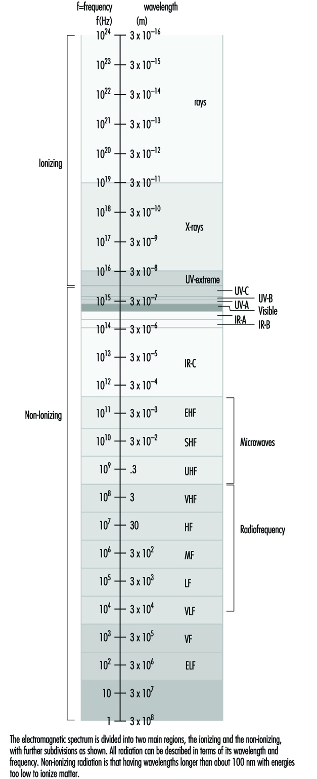
Just as visible light or sound permeates our environment, the space where we live and work, so do the energies of electromagnetic fields. Also, just as most of the sound energy we are exposed to is created by human activity, so too are the electromagnetic energies: from the weak levels emitted from our everyday electrical appliances—those that make our radio and TV sets work—to the high levels that medical practitioners apply for beneficial purposes—for example, diathermy (heat treatments). In general, the strength of such energies decreases rapidly with distance from the source. Natural levels of these fields in the environment are low.
Non-ionizing radiation (NIR) incorporates all radiation and fields of the electromagnetic spectrum that do not have enough energy to produce ionization of matter. That is, NIR is incapable of imparting enough energy to a molecule or atom to disrupt its structure by removing one or more electrons. The borderline between NIR and ionizing radiation is usually set at a wavelength of approximately 100 nanometres.
As with any form of energy, NIR energy has the potential to interact with biological systems, and the outcome may be of no significance, may be harmful in different degrees, or may be beneficial. With radiofrequency (RF) and microwave radiation, the main interaction mechanism is heating, but in the low-frequency part of the spectrum, fields of high intensity may induce currents in the body and thereby be hazardous. The interaction mechanisms for low-level field strengths are, however, unknown.
Quantities and Units
Fields at frequencies below about 300 MHz are quantified in terms of electric field strength (E) and magnetic field strength (H). E is expressed in volts per metre (V/m) and H in amperes per metre (A/m). Both are vector fields—that is, they are characterized by magnitude and direction at each point. For the low-frequency range the magnetic field is often expressed in terms of the flux density, B, with the SI unit tesla (T). When the fields in our daily environment are discussed, the subunit microtesla (μT) is usually the preferred unit. In some literature the flux density is expressed in gauss (G), and the conversion between these units is (for fields in air):
1 T = 104 G or 0.1 μT = 1 mG and 1 A/m = 1.26 μT.
Reviews of concepts, quantities, units and terminology for non-ionizing radiation protection, including radiofrequency radiation, are available (NCRP 1981; Polk and Postow 1986; WHO 1993).
The term radiation simply means energy transmitted by waves. Electromagnetic waves are waves of electric and magnetic forces, where a wave motion is defined as propagation of disturbances in a physical system. A change in the electric field is accompanied by a change in the magnetic field, and vice versa. These phenomena were described in 1865 by J.C. Maxwell in four equations which have come to be known as Maxwell’s Equations.
Electromagnetic waves are characterized by a set of parameters that include frequency (f), wavelength (λ), electric field strength, magnetic field strength, electric polarization (P) (the direction of the E field), velocity of propagation (c) and Poynting vector (S). Figure 2 illustrates the propagation of an electromagnetic wave in free space. The frequency is defined as the number of complete changes of the electric or magnetic field at a given point per second, and is expressed in hertz (Hz). The wavelength is the distance between two consecutive crests or troughs of the wave (maxima or minima). The frequency, wavelength and wave velocity (v) are interrelated as follows:
v = f λ
Figure 2. A plane wave propagating with the speed of light in the x-direction
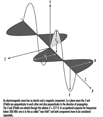
The velocity of an electromagnetic wave in free space is equal to the velocity of light, but the velocity in materials depends on the electrical properties of the material—that is, on its permittivity (ε) and permeability (μ). The permittivity concerns the material interactions with the electric field, and the permeability expresses the interactions with the magnetic field. Biological substances have permittivities that differ vastly from that of free space, being dependant on wavelength (especially in the RF range) and tissue type. The permeability of biological substances, however, is equal to that of free space.
In a plane wave, as illustrated in figure 2 , the electric field is perpendicular to the magnetic field and the direction of propagation is perpendicular to both the electric and the magnetic fields.
For a plane wave, the ratio of the value of the electric field strength to the value of the magnetic field strength, which is constant, is known as the characteristic impedance (Z):
Z = E/H
In free space, Z= 120π ≈ 377Ω but otherwise Z depends on the permittivity and permeability of the material the wave is travelling through.
Energy transfer is described by the Poynting vector, which represents the magnitude and direction of the electromagnetic flux density:
S = E x H
For a propagating wave, the integral of S over any surface represents the instantaneous power transmitted through this surface (power density). The magnitude of the Poynting vector is expressed in watts per square metre (W/m2) (in some literature the unit mW/cm2 is used—the conversion to SI units is 1 mW/cm2 = 10 W/m2) and for plane waves is related to the values of the electric and magnetic field strengths:
S = E2 / 120π = E2 / 377
and
S =120π H2 = 377 H2
Not all exposure conditions encountered in practice can be represented by plane waves. At distances close to sources of radio-frequency radiation the relationships characteristic of plane waves are not satisfied. The electromagnetic field radiated by an antenna can be divided into two regions: the near-field zone and the far-field zone. The boundary between these zones is usually put at:
r = 2a2 / λ
where a is the greatest dimension of the antenna.
In the near-field zone, exposure has to be characterized by both the electric and the magnetic fields. In the far-field one of these suffices, as they are interrelated by the above equations involving E and H. In practice, the near-field situation is often realized at frequencies below 300 Mhz.
Exposure to RF fields is further complicated by interactions of electromagnetic waves with objects. In general, when electromagnetic waves encounter an object some of the incident energy is reflected, some is absorbed and some is transmitted. The proportions of energy transmitted, absorbed or reflected by the object depend on the frequency and polarization of the field and the electrical properties and shape of the object. A superimposition of the incident and reflected waves results in standing waves and spatially non-uniform field distribution. Since waves are totally reflected from metallic objects, standing waves form close to such objects.
Since the interaction of RF fields with biological systems depends on many different field characteristics and the fields encountered in practice are complex, the following factors should be considered in describing exposures to RF fields:
- whether exposure occurs in the near- or far-field zone
- if near-field, then values for both E and H are needed; if far-field, then either E or H
- spatial variation of the magnitude of the field(s)
- field polarization, that is, the direction of the electric field with respect to the direction of wave propagation.
For exposure to low-frequency magnetic fields it is still not clear whether the field strength or flux density is the only important consideration. It may turn out that other factors are also important, such as the exposure time or the rapidity of the field changes.
The term electromagnetic field (EMF), as it is used in the news media and popular press, usually refers to electric and magnetic fields at the low-frequency end of the spectrum, but it can also be used in a much broader sense to include the whole spectrum of electromagnetic radiation. Note that in the low-frequency range the E and B fields are not coupled or interrelated in the same way that they are at higher frequencies, and it is therefore more accurate to refer to them as “electric and magnetic fields” rather than EMFs.
Ultraviolet Radiation
Like light, which is visible, ultraviolet radiation (UVR) is a form of optical radiation with shorter wavelengths and more energetic photons (particles of radiation) than its visible counterpart. Most light sources emit some UVR as well. UVR is present in sunlight and is also emitted from a large number of ultraviolet sources used in industry, science and medicine. Workers may encounter UVR in a wide variety of occupational settings. In some instances, at low ambient light levels, very intense near-ultraviolet (“black light”) sources can be seen, but normally UVR is invisible and must be detected by the glow of materials that fluoresce when illuminated by UVR.
Just as light can be divided into colours which can be seen in a rainbow, UVR is subdivided and its components are commonly denoted as UVA, UVB and UVC. Wavelengths of light and UVR are generally expressed in nanometres (nm); 1 nm is one-billionth (10–9) of a metre. UVC (very short-wavelength UVR) in sunlight is absorbed by the atmosphere and does not reach the Earth’s surface. UVC is available only from artificial sources, such as germicidal lamps, which emit most of their energy at a single wavelength (254 nm) that is very effective in killing bacteria and viruses on a surface or in the air.
UVB is the most biologically damaging UVR to the skin and eye, and although most of this energy (which is a component of sunlight) is absorbed by the atmosphere, it still produces sunburn and other biological effects. Long-wavelength UVR, UVA, is normally found in most lamp sources, and is also the most intense UVR reaching the Earth. Although UVA can penetrate deeply into tissue, it is not as biologically damaging as UVB because the energies of individual photons are less than for UVB or UVC.
Sources of Ultraviolet Radiation
Sunlight
The greatest occupational exposure to UVR is experienced by outdoor workers under sunlight. The energy of solar radiation is greatly attenuated by the earth’s ozone layer, limiting terrestrial UVR to wavelengths greater than 290-295 nm. The energy of the more dangerous short-wavelength (UVB) rays in sunlight is a strong function of the atmospheric slant path, and varies with the season and the time of day (Sliney 1986 and 1987; WHO 1994).
Artificial sources
The most significant artificial sources of human exposure include the following:
Industrial arc welding. The most significant source of potential UVR exposure is the radiant energy of arc-welding equipment. The levels of UVR around arc-welding equipment are very high, and acute injury to the eye and the skin can occur within three to ten minutes of exposure at close viewing distances of a few metres. Eye and skin protection is mandatory.
Industrial/workplace UVR lamps. Many industrial and commercial processes, such as photochemical curing of inks, paints and plastics, involve the use of lamps which strongly emit in the UV range. While the likelihood of harmful exposure is low due to shielding, in some cases accidental exposure can occur.
“Black lights”. Black lights are specialized lamps that emit predominantly in the UV range, and are generally used for non-destructive testing with fluorescent powders, for the authentication of banknotes and documents, and for special effects in advertising and discotheques. These lamps do not pose any significant exposure hazard to humans (except in certain cases to photosensitized skin).
Medical treatment. UVR lamps are used in medicine for a variety of diagnostic and therapeutic purposes. UVA sources are normally used in diagnostic applications. Exposures to the patient vary considerably according to the type of treatment, and UV lamps used in dermatology require careful use by staff members.
Germicidal UVR lamps. UVR with wavelengths in the range 250–265 nm is the most effective for sterilization and disinfection since it corresponds to a maximum in the DNA absorption spectrum. Low-pressure mercury discharge tubes are often used as the UV source, as more than 90% of the radiated energy lies at the 254 nm line. These lamps are often referred to as “germicidal lamps,” “bactericidal lamps” or simply “UVC lamps”. Germicidal lamps are used in hospitals to combat tuberculosis infection, and are also used inside microbiological safety cabinets to inactivate airborne and surface microorganisms. Proper installation of the lamps and the use of eye protection is essential.
Cosmetic tanning. Sunbeds are found in enterprises where clients may obtain a tan by special sun-tanning lamps, which emit primarily in the UVA range but also some UVB. Regular use of a sunbed may contribute significantly to a person’s annual UV skin exposure; furthermore, the staff working in tanning salons may also be exposed to low levels. The use of eye protection such as goggles or sunglasses should be mandatory for the client, and depending upon the arrangement, even staff members may require eye protectors.
General lighting. Fluorescent lamps are common in the workplace and have been used in the home for a long time now. These lamps emit small amounts of UVR and contribute only a few percent to a person’s annual UV exposure. Tungsten-halogen lamps are increasingly used in the home and in the workplace for a variety of lighting and display purposes. Unshielded halogen lamps can emit UVR levels sufficient to cause acute injury at short distances. The fitting of glass filters over these lamps should eliminate this hazard.
Biological Effects
The skin
Erythema
Erythema, or “sunburn”, is a reddening of the skin that normally appears in four to eight hours after exposure to UVR and gradually fades after a few days. Severe sunburn can involve blistering and peeling of the skin. UVB and UVC are both about 1,000 times more effective in causing erythema than UVA (Parrish, Jaenicke and Anderson 1982), but erythema produced by the longer UVB wavelengths (295 to 315 nm) is more severe and persists longer (Hausser 1928). The increased severity and time-course of the erythema results from deeper penetration of these wavelengths into the epidermis. Maximum sensitivity of the skin apparently occurs at approximately 295 nm (Luckiesh, Holladay and Taylor 1930; Coblentz, Stair and Hogue 1931) with much less (approximately 0.07) sensitivity occurring at 315 nm and longer wavelengths (McKinlay and Diffey 1987).
The minimal erythemal dose (MED) for 295 nm that has been reported in more recent studies for untanned, lightly pigmented skin ranges from 6 to 30 mJ/cm2 (Everett, Olsen and Sayer 1965; Freeman, et al. 1966; Berger, Urbach and Davies 1968). The MED at 254 nm varies greatly depending upon the elapsed time after exposure and whether the skin has been exposed much to outdoor sunlight, but is generally of the order of 20 mJ/cm2, or as high as 0.1 J/cm2. Skin pigmentation and tanning, and, most importantly, thickening of the stratum corneum, can increase this MED by at least one order of magnitude.
Photosensitization
Occupational health specialists frequently encounter adverse effects from occupational exposure to UVR in photosensitized workers. The use of certain medicines may produce a photosensitizing effect on exposure to UVA, as may the topical application of certain products, including some perfumes, body lotions and so on. Reactions to photosensitizing agents involve both photoallergy (allergic reaction of the skin) and phototoxicity (irritation of the skin) after UVR exposure from sunlight or industrial UVR sources. (Photosensitivity reactions during the use of tanning equipment are also common.) This photosensitization of the skin may be caused by creams or ointments applied to the skin, by medications taken orally or by injection, or by the use of prescription inhalers (see figure 1 ). The physician prescribing a potentially photosensitizing medication should always warn the patient to take appropriate measures to ensure against adverse effects, but the patient frequently is told only to avoid sunlight and not UVR sources (since these are uncommon for the general population).
Figure 1. Some phonosensitizing substances
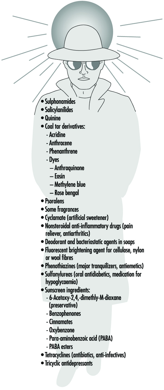
Delayed effects
Chronic exposure to sunlight—especially the UVB component—accelerates the ageing of the skin and increases the risk of developing skin cancer (Fitzpatrick et al. 1974; Forbes and Davies 1982; Urbach 1969; Passchier and Bosnjakovic 1987). Several epidemiological studies have shown that the incidence of skin cancer is strongly correlated with latitude, altitude and sky cover, which correlate with UVR exposure (Scotto, Fears and Gori 1980; WHO 1993).
Exact quantitative dose-response relationships for human skin carcinogenesis have not yet been established, although fair-skinned individuals, particularly those of Celtic origin, are much more prone to develop skin cancer. Nevertheless, it must be noted that the UVR exposures necessary to elicit skin tumours in animal models may be delivered sufficiently slowly that erythema is not produced, and the relative effectiveness (relative to the peak at 302 nm) reported in those studies varies in the same way as sunburn (Cole, Forbes and Davies 1986; Sterenborg and van der Leun 1987).
The eye
Photokeratitis and photoconjunctivitis
These are acute inflammatory reactions resulting from exposure to UVB and UVC radiation which appear within a few hours of excessive exposure and normally resolved after one to two days.
Retinal injury from bright light
Although thermal injury to the retina from light sources is unlikely, photochemical damage can occur from exposure to sources rich in blue light. This can result in temporary or permanent reduction in vision. However the normal aversion response to bright light should prevent this occurrence unless a conscious effort is made to stare at bright light sources. The contribution of UVR to retinal injury is generally very small because absorption by the lens limits retinal exposure.
Chronic effects
Long-term occupational exposure to UVR over several decades may contribute to cataract and such non-eye-related degenerative effects as skin ageing and skin cancer associated with sun exposure. Chronic exposure to infrared radiation also can increase the risk of cataract, but this is very unlikely, given access to eye protection.
Actinic ultraviolet radiation (UVB and UVC) is strongly absorbed by the cornea and conjunctiva. Overexposure of these tissues causes keratoconjunctivitis, commonly referred to as “welder’s flash”, “arc-eye” or “snow-blindness”. Pitts has reported the action spectrum and time course of photokeratitis in the human, rabbit and monkey cornea (Pitts 1974). The latent period varies inversely with the severity of exposure, ranging from 1.5 to 24 hours, but usually occurs within 6 to 12 hours; discomfort usually disappears within 48 hours. Conjunctivitis follows and may be accompanied by erythema of the facial skin surrounding the eyelids. Of course, UVR exposure rarely results in permanent ocular injury. Pitts and Tredici (1971) reported threshold data for photokeratitis in humans for wavebands 10 nm in width from 220 to 310 nm. The maximum sensitivity of the cornea was found to occur at 270 nm—differing markedly from the maximum for the skin. Presumably, 270 nm radiation is biologically more active because of the lack of a stratum corneum to attenuate the dose to the corneal epithelium tissue at shorter UVR wavelengths. The wavelength response, or action spectrum, did not vary as greatly as did the erythema action spectra, with thresholds varying from 4 to 14 mJ/cm2 at 270 nm. The threshold reported at 308 nm was approximately 100 mJ/cm2.
Repeated exposure of the eye to potentially hazardous levels of UVR does not increase the protective capability of the affected tissue (the cornea) as does skin exposure, which leads to tanning and to thickening of the stratum corneum. Ringvold and associates studied the UVR absorption properties of the cornea (Ringvold 1980a) and aqueous humour (Ringvold 1980b), as well as the effects of UVB radiation upon the corneal epithelium (Ringvold 1983), the corneal stroma (Ringvold and Davanger 1985) and the corneal endothelium (Ringvold, Davanger and Olsen 1982; Olsen and Ringvold 1982). Their electron microscopic studies showed that corneal tissue possessed remarkable repair and recovery properties. Although one could readily detect significant damage to all of these layers apparently appearing initially in cell membranes, morphological recovery was complete after a week. Destruction of keratocytes in the stromal layer was apparent, and endothelial recovery was pronounced despite the normal lack of rapid cell turnover in the endothelium. Cullen et al. (1984) studied endothelial damage that was persistent if the UVR exposure was persistent. Riley et al. (1987) also studied the corneal endothelium following UVB exposure and concluded that severe, single insults were not likely to have delayed effects; however, they also concluded that chronic exposure could accelerate changes in the endothelium related to ageing of the cornea.
Wavelengths above 295 nm can be transmitted through the cornea and are almost totally absorbed by the lens. Pitts, Cullen and Hacker (1977b) showed that cataracts can be produced in rabbits by wavelengths in the 295–320 nm band. Thresholds for transient opacities ranged from 0.15 to 12.6 J/cm2, depending on wavelength, with a minimum threshold at 300 nm. Permanent opacities required greater radiant exposures. No lenticular effects were noted in the wavelength range of 325 to 395 nm even with much higher radiant exposures of 28 to 162 J/cm2 (Pitts, Cullen and Hacker 1977a; Zuclich and Connolly 1976). These studies clearly illustrate the particular hazard of the 300-315 nm spectral band, as would be expected because photons of these wavelengths penetrate efficiently and have sufficient energy to produce photochemical damage.
Taylor et al. (1988) provided epidemiological evidence that UVB in sunlight was an aetiological factor in senile cataract, but showed no correlation of cataract with UVA exposure. Although once a popular belief because of the strong absorption of UVA by the lens, the hypothesis that UVA can cause cataract has not been supported by either experimental laboratory studies or by epidemiological studies. From the laboratory experimental data which showed that thresholds for photokeratitis were lower than for cataractogenesis, one must conclude that levels lower than those required to produce photokeratitis on a daily basis should be considered hazardous to lens tissue. Even if one were to assume that the cornea is exposed to a level nearly equivalent to the threshold for photokeratitis, one would estimate that the daily UVR dose to the lens at 308 nm would be less than 120 mJ/cm2 for 12 hours out of doors (Sliney 1987). Indeed, a more realistic average daily exposure would be less than half that value.
Ham et al. (1982) determined the action spectrum for photoretinitis produced by UVR in the 320–400 nm band. They showed that thresholds in the visible spectral band, which were 20 to 30 J/cm2 at 440 nm, were reduced to approximately 5 J/cm2 for a 10 nm band centred at 325 nm. The action spectrum was increasing monotonically with decreasing wavelength. We should therefore conclude that levels well below 5 J/cm2 at 308 nm should produce retinal lesions, although these lesions would not become apparent for 24 to 48 hours after the exposure. There are no published data for retinal injury thresholds below 325 nm, and one can only expect that the pattern for the action spectrum for photochemical injury to the cornea and lens tissues would apply to the retina as well, leading to an injury threshold of the order of 0.1 J/cm2.
Although UVB radiation has been clearly shown to be mutagenic and carcinogenic to the skin, the extreme rarity of carcinogenesis in the cornea and conjunctiva is quite remarkable. There appears to be no scientific evidence to link UVR exposure with any cancers of the cornea or conjunctiva in humans, although the same is not true of cattle. This would suggest a very effective immune system operating in the human eye, since there are certainly outdoor workers who receive a UVR exposure comparable to that which cattle receive. This conclusion is further supported by the fact that individuals suffering from a defective immune response, as in xeroderma pigmentosum, frequently develop neoplasias of the cornea and conjunctiva (Stenson 1982).
Safety Standards
Occupational exposure limits (EL) for UVR have been developed and include an action spectrum curve which envelops the threshold data for acute effects obtained from studies of minimal erythema and keratoconjunctivitis (Sliney 1972; IRPA 1989). This curve does not differ significantly from the collective threshold data, considering measurement errors and variations in individual response, and is well below the UVB cataractogenic thresholds.
The EL for UVR is lowest at 270 nm (0.003 J/cm2 at 270 nm), and, for example, at 308 nm is 0.12 J/cm2 (ACGIH 1995, IRPA 1988). Regardless of whether the exposure occurs from a few pulsed exposures during the day, a single very brief exposure, or from an 8-hour exposure at a few microwatts per square centimetre, the biological hazard is the same, and the above limits apply to the full workday.
Occupational Protection
Occupational exposure to UVR should be minimized where practical. For artificial sources, wherever possible, priority should be given to engineering measures such as filtration, shielding and enclosure. Administrative controls, such as limitation of access, can reduce the requirements for personal protection.
Outdoor workers such as agricultural workers, labourers, construction workers, fishermen and so on can minimize their risk from solar UV exposure by wearing appropriate tightly woven clothing, and most important, a brimmed hat to reduce face and neck exposure. Sunscreens can be applied to exposed skin to reduce further exposure. Outdoor workers should have access to shade and be provided with all the necessary protective measures mentioned above.
In industry, there are many sources capable of causing acute eye injury within a short exposure time. A variety of eye protection is available with various degrees of protection appropriate to the intended use. Those intended for industrial use include welding helmets (additionally providing protection both from intense visible and infrared radiation as well as face protection), face shields, goggles and UV-absorbing spectacles. In general, protective eyewear provided for industrial use should fit snugly on the face, thus ensuring that there are no gaps through which UVR can directly reach the eye, and they should be well-constructed to prevent physical injury.
The appropriateness and selection of protective eyewear is dependent on the following points:
- the intensity and spectral emission characteristics of the UVR source
- the behavioural patterns of people near UVR sources (distance and exposure time are important)
- the transmission properties of the protective eyewear material
- the design of the frame of the eyewear to prevent peripheral exposure of the eye from direct unabsorbed UVR.
In industrial exposure situations, the degree of ocular hazard can be assessed by measurement and comparison with recommended limits for exposure (Duchene, Lakey and Repacholi 1991).
Measurement
Because of the strong dependence of biological effects on wavelength, the principal measurement of any UVR source is its spectral power or spectral irradiance distribution. This must be measured with a spectroradiometer which consists of suitable input optics, a monochromator and a UVR detector and readout. Such an instrument is not normally used in occupational hygiene.
In many practical situations, a broad-band UVR meter is used to determine safe exposure durations. For safety purposes, the spectral response can be tailored to follow the spectral function used for the exposure guidelines of the ACGIH and the IRPA. If appropriate instruments are not used, serious errors of hazard assessment will result. Personal UVR dosimeters are also available (e.g., polysulphone film), but their application has been largely confined to occupational safety research rather than in hazard evaluation surveys.
Conclusions
Molecular damage of key cellular components arising from UVR exposure occurs constantly, and repair mechanisms exist to deal with the exposure of skin and ocular tissues to ultraviolet radiation. Only when these repair mechanisms are overwhelmed does acute biological injury become apparent (Smith 1988). For these reasons, minimizing occupational UVR exposure continues to remain an important object of concern among occupational health and safety workers.
Infrared Radiation
Infrared radiation is that part of the non-ionizing radiation spectrum located between microwaves and visible light. It is a natural part of the human environment and thus people are exposed to it in small amounts in all areas of daily life—for example, at home or during recreational activities in the sun. Very intense exposure, however, may result from certain technical processes at the workplace.
Many industrial processes involve thermal curing of various kinds of materials. The heat sources used or the heated material itself will usually emit such high levels of infrared radiation that a large number of workers are potentially at risk of being exposed.
Concepts and Quantities
Infrared radiation (IR) has wavelengths ranging from 780 nm to 1 mm. Following the classification by the International Commission on Illumination (CIE), this band is subdivided into IRA (from 780 nm to 1.4 μm), IRB (from 1.4 μm to 3 μm) and IRC (from 3 μm to 1 mm). This subdivision approximately follows the wavelength-dependent absorption characteristics of IR in tissue and the resulting different biological effects.
The amount and the temporal and spatial distribution of infrared radiation are described by different radiometric quantities and units. Due to optical and physiological properties, especially of the eye, a distinction is usually made between small “point” sources and “extended” sources. The criterion for this distinction is the value in radians of the angle (α) measured at the eye that is subtended by the source. This angle can be calculated as a quotient, the light source dimension DL divided by the viewing distance r. Extended sources are those which subtend a viewing angle at the eye greater than αmin, which normally is 11 milliradians. For all extended sources there is a viewing distance where α equals αmin; at greater viewing distances, the source can be treated like a point source. In optical radiation protection the most important quantities concerning extended sources are the radiance (L, expressed in Wm–2sr–1) and the time-integrated radiance (Lp in Jm–2sr–1), which describe the “brightness” of the source. For health risk assessment, the most relevant quantities concerning point sources or exposures at such distances from the source where α< αmin, are the irradiance (E, expressed in Wm–2), which is equivalent to the concept of exposure dose rate, and the radiant exposure (H, in Jm–2), equivalent to the exposure dose concept.
In some bands of the spectrum, the biological effects due to exposure are strongly dependent on wavelength. Therefore, additional spectroradiometric quantities must be used (e.g., the spectral radiance, Ll, expressed in Wm–2 sr–1 nm–1) to weigh the physical emission values of the source against the applicable action spectrum related to the biological effect.
Sources and Occupational Exposure
Exposure to IR results from various natural and artificial sources. The spectral emission from these sources may be limited to a single wavelength (laser) or may be distributed over a broad wavelength band.
The different mechanisms for the generation of optical radiation in general are:
- thermal excitation (black-body radiation)
- gas discharge
- light amplification by stimulated emission of radiation (laser), with the mechanism of gas discharge being of lesser importance in the IR band.
The emission from the most important sources used in many industrial processes results from thermal excitation, and can be approximated using the physical laws of black-body radiation if the absolute temperature of the source is known. The total emission (M, in Wm–2) of a black-body radiator (figure 1) is described by the Stefan-Boltzmann law:
M(T) = 5.67 x 10⁻⁸T4
and depends on the 4th power of the temperature (T, in K) of the radiating body. The spectral distribution of the radiance is described by Planck’s radiation law:

and the wavelength of maximum emission (λmax) is described according to Wien’s law by:
λmax = (2.898 x 10⁻⁸) / T
Figure 1. Spectral radiance λmaxof a black body radiator at the absolute temperature shown in degrees Kelvin on each curve
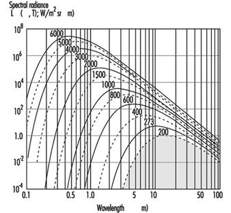
Many lasers used in industrial and medical processes will emit very high levels of IR. In general, compared with other radiation sources, laser radiation has some unusual features that may influence the risk following an exposure, such as very short pulse duration or extremely high irradiance. Therefore, laser radiation is discussed in detail elsewhere in this chapter.
Many industrial processes require the use of sources emitting high levels of visible and infrared radiation, and thus a large number of workers like bakers, glass blowers, kiln workers, foundry workers, blacksmiths, smelters and fire-fighters are potentially at risk of exposure. In addition to lamps, such sources as flames, gas torches, acetylene torches, pools of molten metal and incandescent metal bars must be considered. These are encountered in foundries, steel mills and in many other heavy industrial plants. Table 1 summarizes some examples of IR sources and their applications.
Table 1. Different sources of IR, population exposed and approximate exposure levels
|
Source |
Application or exposed population |
Exposure |
|
Sunlight |
Outdoor workers, farmers, construction workers, seafarers, general public |
500 Wm–2 |
|
Tungsten filament lamps |
General population and workers |
105–106 Wm–2sr–1 |
|
Tungsten halogen filament lamps |
(See tungsten filament lamps) |
50–200 Wm–2 (at 50 cm) |
|
Light emitting diodes (e.g. GaAs diode) |
Toys, consumer electronics, data transmission technology, etc. |
105 Wm–2sr–1 |
|
Xenon arc lamps |
Projectors, solar simulators, search lights |
107 Wm–2sr–1 |
|
Iron melt |
Steel furnace, steel mill workers |
105 Wm–2sr–1 |
|
Infrared lamp arrays |
Industrial heating and drying |
103 to 8.103 Wm–2 |
|
Infrared lamps in hospitals |
Incubators |
100–300 Wm–2 |
Biological Effects
Optical radiation in general does not penetrate very deeply into biological tissue. Therefore, the primary targets of an IR exposure are the skin and the eye. Under most exposure conditions the main interaction mechanism of IR is thermal. Only the very short pulses that lasers may produce, but which are not considered here, can also lead to mechanothermal effects. Effects from ionization or from the breakage of chemical bonds are not expected to appear with IR radiation because the particle energy, being less than approximately 1.6 eV, is too low to cause such effects. For the same reason, photochemical reactions become significant only at shorter wavelengths in the visual and in the ultraviolet region. The different wavelength-dependent health effects of IR arise mainly from the wavelength-dependent optical properties of tissue—for example, the spectral absorption of the ocular media (figure 2).
Figure 2. Spectral absorption of the ocular media
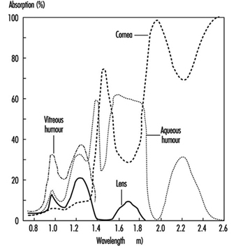
Effects on the eye
In general, the eye is well adapted to protect itself against optical radiation from the natural environment. In addition, the eye is physiologically protected against injury from bright light sources, such as the sun or high intensity lamps, by an aversion response that limits the duration of exposure to a fraction of a second (approximately 0.25 seconds).
IRA affects primarily the retina, because of the transparency of the ocular media. When directly viewing a point source or laser beam, the focusing properties in the IRA region additionally render the retina much more susceptible to damage than any other part of the body. For short exposure periods, heating of the iris from the absorption of visible or near IR is considered to play a role in the development of opacities in the lens.
With increasing wavelength, above approximately 1 μm, the absorption by ocular media increases. Therefore, absorption of IRA radiation by both the lens and the pigmented iris is considered to play a role in the formation of lenticular opacities. Damage to the lens is attributed to wavelengths below 3 μm (IRA and IRB). For infrared radiation of wavelengths longer than 1.4 μm, the aqueous humour and the lens are particularly strongly absorbent.
In the IRB and IRC region of the spectrum, the ocular media become opaque as a result of the strong absorption by their constituent water. Absorption in this region is primarily in the cornea and in the aqueous humour. Beyond 1.9 μm, the cornea is effectively the sole absorber. The absorption of long wavelength infrared radiation by the cornea may lead to increased temperatures in the eye due to thermal conduction. Because of a quick turnover rate of the surface corneal cells, any damage limited to the outer corneal layer can be expected to be temporary. In the IRC band the exposure can cause a burn on the cornea similar to that on the skin. Corneal burns are not very likely to occur, however, because of the aversion reaction triggered by the painful sensation caused by strong exposure.
Effects on the skin
Infrared radiation will not penetrate the skin very deeply. Therefore, exposure of the skin to very strong IR may lead to local thermal effects of different severity, and even serious burns. The effects on the skin depend on the optical properties of the skin, such as wavelength-dependent depth of penetration (figure 3 ). Especially at longer wavelengths, an extensive exposure may cause a high local temperature rise and burns. The threshold values for these effects are time dependent, because of the physical properties of the thermal transport processes in the skin. An irradiation of 10 kWm–2, for example, may cause a painful sensation within 5 seconds, whereas an exposure of 2 kWm–2 will not cause the same reaction within periods shorter than approximately 50 seconds.
Figure 3. Depth of penetration into the skin for different wavelengths
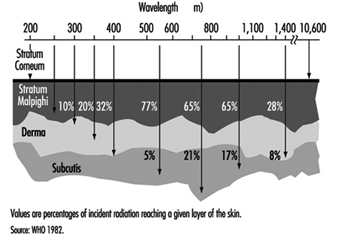
If the exposure is extended over very long periods, even at values well below the pain threshold, the burden of heat to the human body may be great. Especially if the exposure covers the whole body as, for example, in front of a steel melt. The result may be an imbalance of the otherwise physiologically well balanced thermoregulation system. The threshold for tolerating such an exposure will depend on different individual and environmental conditions, such as the individual capacity of the thermoregulation system, the actual body metabolism during exposure or the environmental temperature, humidity and air movement (wind speed). Without any physical work, a maximum exposure of 300 Wm–2 may be tolerated over eight hours under certain environmental conditions, but this value decreases to approximately 140 Wm–2 during heavy physical work.
Exposure Standards
The biological effects of IR exposure which are dependent on wavelength and on the duration of exposure, are intolerable only if certain threshold intensity or dose values are exceeded. To protect against such intolerable exposure conditions, international organizations such as the World Health Organization (WHO), the International Labour Office (ILO), the International Committee for Non-Ionizing Radiation of the International Radiation Protection Association (INIRC/IRPA), and its successor, the International Commission on Non-Ionizing Radiation Protection (ICNIRP) and the American Conference of Governmental Industrial Hygienists (ACGIH) have suggested exposure limits for infrared radiation from both coherent and incoherent optical sources. Most of the national and international suggestions on guidelines for limiting human exposure to infrared radiation are either based on or even identical with the suggested threshold limit values (TLVs) published by the ACGIH (1993/1994). These limits are widely recognized and are frequently used in occupational situations. They are based on current scientific knowledge and are intended to prevent thermal injury of the retina and cornea and to avoid possible delayed effects on the lens of the eye.
The 1994 revision of the ACGIH exposure limits is as follows:
1. For the protection of the retina from thermal injury in case of exposure to visible light, (for example, in the case of powerful light sources), the spectral radiance Lλ in W/(m² sr nm) weighted against the retinal thermal hazard function Rλ (see table 2) over the wavelength interval Δλ and summed over the range of wavelength 400 to 1400 nm, should not exceed:
![]()
where t is the viewing duration limited to intervals from 10-3 to 10 seconds (that is, for accidental viewing conditions, not fixated viewing), and α is the angular subtense of the source in radians calculated by α = maximum extension of the source/distance to the source Rλ (table 2 ).
2. To protect the retina from the exposure hazards of infrared heat lamps or any near IR source where a strong visual stimulus is absent, the infrared radiance over the wavelength range 770 to 1400 nm as viewed by the eye (based on a 7 mm pupil diameter) for extended duration of viewing conditions should be limited to:
![]()
This limit is based on a pupil diameter of 7 mm since, in this case, the aversion response (closing the eye, for example) may not exist due to the absence of visible light.
3. To avoid possible delayed effects on the lens of the eye, such as delayed cataract, and to protect the cornea from overexposure, the infrared radiation at wavelengths greater than 770 nm should be limited to 100 W/m² for periods greater than 1,000 s and to:
![]()
or for shorter periods.
4. For aphakic patients, separate weighting functions and resulting TLVs are given for the wavelength range of ultraviolet and visible light (305–700 nm).
Table 2. Retinal thermal hazard function
|
Wavelength (nm) |
Rλ |
Wavelength (nm) |
Rλ |
|
400 |
1.0 |
460 |
8.0 |
|
405 |
2.0 |
465 |
7.0 |
|
410 |
4.0 |
470 |
6.2 |
|
415 |
8.0 |
475 |
5.5 |
|
420 |
9.0 |
480 |
4.5 |
|
425 |
9.5 |
485 |
4.0 |
|
430 |
9.8 |
490 |
2.2 |
|
435 |
10.0 |
495 |
1.6 |
|
440 |
10.0 |
500–700 |
1.0 |
|
445 |
9.7 |
700–1,050 |
10((700 - λ )/500) |
|
450 |
9.4 |
1,050–1,400 |
0.2 |
|
455 |
9.0 |
Source: ACGIH 1996.
Measurement
Reliable radiometric techniques and instruments are available that make it possible to analyse the risk to the skin and the eye from exposure to sources of optical radiation. For characterizing a conventional light source, it is generally very useful to measure the radiance. For defining hazardous exposure conditions from optical sources, the irradiance and the radiant exposure are of greater importance. The evaluation of broad-band sources is more complex than the evaluation of sources that emit at single wavelengths or very narrow bands, since spectral characteristics and source size must be considered. The spectrum of certain lamps consists of both a continuum emission over a wide wavelength band and emission on certain single wavelengths (lines). Significant errors may be introduced into the representation of those spectra if the fraction of energy in each line is not properly added to the continuum.
For health-hazard assessment the exposure values must be measured over a limiting aperture for which the exposure standards are specified. Typically a 1 mm aperture has been considered to be the smallest practical aperture size. Wavelengths greater than 0.1 mm present difficulties because of significant diffraction effects created by a 1 mm aperture. For this wavelength band an aperture of 1 cm² (11 mm diameter) was accepted, because hot spots in this band are larger than at shorter wavelengths. For the evaluation of retinal hazards, the size of the aperture was determined by an average pupil size and therefore an aperture of 7 mm was chosen.
In general, measurements in the optical region are very complex. Measurements taken by untrained personnel may lead to invalid conclusions. A detailed summary of measurement procedures is to be found in Sliney and Wolbarsht (1980).
Protective Measures
The most effective standard protection from exposure to optical radiation is the total enclosure of the source and all of the radiation pathways that may exit from the source. By such measures, compliance with the exposure limits should be easy to achieve in the majority of cases. Where this is not the case, personal protection is applicable. For example, available eye protection in the form of suitable goggles or visors or protective clothing should be used. If the work conditions will not allow for such measures to be applied, administrative control and restricted access to very intense sources may be necessary. In some cases a reduction of either the power of the source or the working time (work pauses to recover from heat stress), or both, might be a possible measure to protect the worker.
Conclusion
In general, infrared radiation from the most common sources such as lamps, or from most industrial applications, will not cause any risk to workers. At some workplaces, however, IR can cause a health risk for the worker. In addition, there is a rapid increase in the application and use of special-purpose lamps and in high temperature processes in industry, science and medicine. If the exposure from those applications is sufficiently high, detrimental effects (mainly in the eye but also on the skin) cannot be excluded. The importance of internationally recognized optical radiation exposure standards is expected to increase. To protect the worker from excessive exposure, protective measures like shielding (eye shields) or protective clothing should be mandatory.
The principal adverse biological effects attributed to infrared radiation are cataracts, known as glass blower’s or furnaceman’s cataracts. Long-term exposure even at relatively low levels causes heat stress to the human body. At such exposure conditions additional factors such as body temperature and evaporative heat loss as well as environmental factors must be considered.
In order to inform and instruct workers some practical guides were developed in industrial countries. A comprehensive summary can be found in Sliney and Wolbarsht (1980).
Light and Infrared Radiation
Light and infrared (IR) radiant energy are two forms of optical radiation, and together with ultraviolet radiation, they form the optical spectrum. Within the optical spectrum, different wavelengths have considerably different potentials for causing biological effects, and for this reason the optical spectrum may be further subdivided.
The term light should be reserved for wavelengths of radiant energy between 400 and 760 nm, which evoke a visual response at the retina (CIE 1987). Light is the essential component of the output of illuminating lamps, visual displays and a wide variety of illuminators. Aside from the importance of illumination for seeing, some light sources may, however, pose unwanted physiological reactions such as disability and discomfort glare, flicker and other forms of eye stress due to poor ergonomic design of workplace tasks. The emission of intense light is also a potentially hazardous side-effect of some industrial processes, such as arc welding.
Infrared radiation (IRR, wavelengths 760 nm to 1 mm) may also be referred to quite commonly as thermal radiation (or radiant heat), and is emitted from any warm object (hot engines, molten metals and other foundry sources, heat-treated surfaces, incandescent electric lamps, radiant heating systems, etc.). Infrared radiation is also emitted from a large variety of electrical equipment such as electric motors, generators, transformers and various electronic equipment.
Infrared radiation is a contributory factor in heat stress. High ambient air temperature and humidity and a low degree of air circulation can combine with radiant heat to produce heat stress with the potential for heat injuries. In cooler environments, unwelcome or poorly designed sources of radiant heat can also produce discomfort—an ergonomic consideration.
Biological Effects
Occupational hazards presented to the eye and skin by visible and infrared forms of radiation are limited by the eye’s aversion to bright light and the pain sensation in the skin resulting from intense radiant heating. The eye is well-adapted to protect itself against acute optical radiation injury (due to ultraviolet, visible or infrared radiant energy) from ambient sunlight. It is protected by a natural aversion response to viewing bright light sources that normally protects it against injury arising from exposure to sources such as the sun, arc lamps and welding arcs, since this aversion limits the duration of exposure to a fraction (about two-tenths) of a second. However, sources rich in IRR without a strong visual stimulus can be hazardous to the lens of the eye in the case of chronic exposure. One can also force oneself to stare at the sun, a welding arc or a snow field and thereby suffer a temporary (and sometimes a permanent) loss of vision. In an industrial setting in which bright lights appear low in the field of view, the eye’s protective mechanisms are less effective, and hazard precautions are particularly important.
There are at least five separate types of hazards to the eye and skin from intense light and IRR sources, and protective measures must be chosen with an understanding of each. In addition to the potential hazards presented by ultraviolet radiation (UVR) from some intense light sources, one should consider the following hazards (Sliney and Wolbarsht 1980; WHO 1982):
- Thermal injury to the retina, which can occur at wavelengths from 400 nm to 1,400 nm. Normally the danger of this type of injury is posed only by lasers, a very intense xenon-arc source or a nuclear fireball. The local burning of the retina results in a blind spot (scotoma).
- Blue-light photochemical injury to the retina (a hazard principally associated with blue light of wavelengths from 400 nm to 550 nm) (Ham 1989). The injury is commonly termed “blue light” photoretinitis; a particular form of this injury is named, according to its source, solar retinitis. Solar retinitis was once referred to as “eclipse blindness” and associated “retinal burn”. Only in recent years has it become clear that photoretinitis results from a photochemical injury mechanism following exposure of the retina to shorter wavelengths in the visible spectrum, namely, violet and blue light. Until the 1970s, it was thought to be the result of a thermal injury mechanism. In contrast to blue light, IRA radiation is very ineffective in producing retinal injuries. (Ham 1989; Sliney and Wolbarsht 1980).
- Near-infrared thermal hazards to the lens (associated with wavelengths of approximately 800 nm to 3,000 nm) with potential for industrial heat cataract. The average corneal exposure to infrared radiation in sunlight is of the order of 10 W/m2. By comparison, glass and steel workers exposed to infrared irradiances of the order of 0.8 to 4 kW/m2 daily for 10 to 15 years have reportedly developed lenticular opacities (Sliney and Wolbarsht 1980). These spectral bands include IRA and IRB (see figure 1). The American Conference of Governmental Industrial Hygienists (ACGIH) guideline for IRA exposure of the anterior of the eye is a time-weighted total irradiance of 100 W/m2 for exposure durations exceeding 1,000 s (16.7 min) (ACGIH 1992 and 1995).
- Thermal injury of the cornea and conjunctiva (at wavelengths of approximately 1,400 nm to 1 mm). This type of injury is almost exclusively limited to exposure to laser radiation.
- Thermal injury of the skin. This is rare from conventional sources but can occur across the entire optical spectrum.
The importance of wavelength and time of exposure
Thermal injuries (1) and (4) above are generally limited to very brief exposure durations, and eye protection is designed to prevent these acute injuries. However, photochemical injuries, such as are mentioned in (2) above, can result from low dose rates spread over the entire workday. The product of the dose rate and the exposure duration always results in the dose (it is the dose that governs the degree of photochemical hazard). As with any photochemical injury mechanism, one must consider the action spectrum which describes the relative effectiveness of different wavelengths in causing a photobiological effect. For example, the action spectrum for photochemical retinal injury peaks at approximately 440 nm (Ham 1989). Most photochemical effects are limited to a very narrow range of wavelengths; whereas a thermal effect can occur at any wavelength in the spectrum. Hence, eye protection for these specific effects need block only a relatively narrow spectral band in order to be effective. Normally, more than one spectral band must be filtered in eye protection for a broad-band source.
Sources of Optical Radiation
Sunlight
The greatest occupational exposure to optical radiation results from exposure of outdoor workers to the sun’s rays. The solar spectrum extends from the stratospheric ozone-layer cut-off of about of 290-295 nm in the ultraviolet band to at least 5,000 nm (5 μm) in the infrared band. Solar radiation can attain a level as high as 1 kW/m2 during the summer months. It can result in heat stress, depending upon ambient air temperature and humidity.
Artificial sources
The most significant artificial sources of human exposure to optical radiation include the following:
- Welding and cutting. Welders and their co-workers are typically exposed not only to intense UV radiation, but also to intense visible and IR radiation emitted from the arc. Under rare instances, these sources have produced acute injury to the retina of the eye. Eye protection is mandatory for these environments.
- Metals industries and foundries. The most significant source of visible and infrared exposure are from molten and hot metal surfaces in the steel and aluminium industries and in foundries. Worker exposure typically ranges from 0.5 to 1.2 kW/m2.
- Arc lamps. Many industrial and commercial processes, such as those involving photochemical curing lamps, emit intense, short-wave visible (blue) light as well as UV and IR radiation. While the likelihood of harmful exposure is low due to shielding, in some cases accidental exposure can occur.
- Infrared lamps. These lamps emit predominantly in the IRA range and are generally used for heat treatment, paint drying and related applications. These lamps do not pose any significant exposure hazard to humans since the discomfort produced upon exposure will limit exposure to a safe level.
- Medical treatment. Infrared lamps are used in physical medicine for a variety of diagnostic and therapeutic purposes. Exposures to the patient vary considerably according to the type of treatment, and IR lamps require careful use by staff members.
- General lighting. Fluorescent lamps emit very little infrared and are generally not bright enough to pose a potential hazard to the eye. Tungsten and tungsten-halogen incandescent lamps emit a large fraction of their radiant energy in the infrared. Additionally, the blue light emitted by tungsten-halogen lamps can pose a retinal hazard if a person stares at the filament. Fortunately, the eye’s aversion response to bright light prevents acute injury even at short distances. Placing glass “heat” filters over these lamps should minimize/eliminate this hazard.
- Optical projectors and other devices. Intense light sources are used in searchlights, film projectors and other light-beam collimating devices. These may pose a retinal hazard with the direct beam at very close distances.
Measurement of Source Properties
The most important characteristic of any optical source is its spectral power distribution. This is measured using a spectroradiometer, which consists of suitable input optics, a monochromator and a photodetector.
In many practical situations, a broad-band optical radiometer is used to select a given spectral region. For both visible illumination and safety purposes, the spectral response of the instrument will be tailored to follow a biological spectral response; for example, lux-meters are geared to the photopic (visual) response of the eye. Normally, aside from UVR hazard meters, the measurement and hazard analysis of intense light sources and infrared sources is too complex for routine occupational health and safety specialists. Progress is being made in standardizations of safety categories of lamps, so that measurements by the user will not be required in order to determine potential hazards.
Human Exposure Limits
From knowledge of the optical parameters of the human eye and the radiance of a light source, it is possible to calculate irradiances (dose rates) at the retina. Exposure of the anterior structures of the human eye to infrared radiation may also be of interest, and it should be further borne in mind that the relative position of the light source and the degree of lid closure can greatly affect the proper calculation of an ocular exposure dose. For ultraviolet and short-wavelength light exposures, the spectral distribution of the light source is also important.
A number of national and international groups have recommended occupational exposure limits (ELs) for optical radiation (ACGIH 1992 and 1994; Sliney 1992). Although most such groups have recommended ELs for UV and laser radiation, only one group has recommended ELs for visible radiation (i.e., light), namely, the ACGIH, an agency well-known in the field of occupational health. The ACGIH refers to its ELs as threshold limit values, or TLVs, and as these are issued yearly, there is an opportunity for a yearly revision (ACGIH 1992 and 1995). They are based in large part on ocular injury data from animal studies and from data from human retinal injuries resulting from viewing the sun and welding arcs. TLVs are furthermore based on the underlying assumption that outdoor environmental exposures to visible radiant energy are normally not hazardous to the eye except in very unusual environments, such as snow fields and deserts, or when one actually fixes the eyes on the sun.
Optical Radiation Safety Evaluation
Since a comprehensive hazard evaluation requires complex measurements of spectral irradiance and radiance of the source, and sometimes very specialized instruments and calculations as well, it is rarely carried out onsite by industrial hygienists and safety engineers. Instead, the eye protective equipment to be deployed is mandated by safety regulations in hazardous environments. Research studies evaluated a wide range of arcs, lasers and thermal sources in order to develop broad recommendations for practical, easier-to-apply safety standards.
Protective Measures
Occupational exposure to visible and IR radiation is seldom hazardous and is usually beneficial. However, some sources emit a considerable amount of visible radiation, and in this case, the natural aversion response is evoked, so there is little chance of accidental overexposure of the eyes. On the other hand, accidental exposure is quite likely in the case of artificial sources emitting only near-IR radiation. Measures which can be taken to minimize the unnecessary exposure of staff to IR radiation include proper engineering design of the optical system in use, wearing appropriate goggles or face visors, limiting access to persons directly concerned with the work, and ensuring that workers are aware of the potential hazards associated with exposure to intense visible and IR radiation sources. Maintainance staff who replace arc lamps must have adequate training so as to preclude hazardous exposure. It is unacceptable for workers to experience either skin erythema or photokeratitis. If these conditions do occur, working practices should be examined and steps taken to ensure that overexposure is made unlikely in the future. Pregnant operators are at no specific risk to optical radiation as regards the integrity of their pregnancy.
Eye protector design and standards
The design of eye protectors for welding and other operations presenting sources of industrial optical radiation (e.g., foundry work, steel and glass manufacture) started at the beginning of this century with the development of Crooke’s glass. Eye protector standards which evolved later followed the general principle that since infrared and ultraviolet radiation are not needed for vision, those spectral bands should be blocked as best as possible by currently available glass materials.
The empirical standards for eye protective equipment were tested in the 1970s and were shown to have included large safety factors for infrared and ultraviolet radiation when the transmission factors were tested against current occupational exposure limits, whereas the protection factors for blue light were just sufficient. Some standards’ requirements were therefore adjusted.
Ultraviolet and infrared radiation protection
A number of specialized UV lamps are used in industry for fluorescence detection and for photocuring of inks, plastic resins, dental polymers and so on. Although UVA sources normally pose little risk, these sources may either contain trace amounts of hazardous UVB or pose a disability glare problem (from fluorescence of the eye’s crystalline lens). UV filter lenses, glass or plastic, with very high attenuation factors are widely available to protect against the entire UV spectrum. A slight yellowish tint may be detectable if protection is afforded to 400 nm. It is of paramount importance for this type of eyewear (and for industrial sunglasses) to provide protection for the peripheral field of vision. Side shields or wraparound designs are important to protect against the focusing of temporal, oblique rays into the nasal equatorial area of the lens, where cortical cataract frequently originates.
Almost all glass and plastic lens materials block ultraviolet radiation below 300 nm and infrared radiation at wavelengths greater than 3,000 nm (3 μm), and for a few lasers and optical sources, ordinary impact-resistant clear safety eyewear will provide good protection (e.g., clear polycarbonate lenses effectively block wavelengths greater than 3 μm). However, absorbers such as metal oxides in glass or organic dyes in plastics must be added to eliminate UV up to about 380–400 nm, and infrared beyond 780 nm to 3 μm. Depending upon the material, this may be either easy or very difficult or expensive, and the stability of the absorber may vary somewhat. Filters that meet the American National Standards Institute’s ANSI Z87.1 standard must have the appropriate attenuation factors in each critical spectral band.
Protection in various industries
Fire-fighting
Fire-fighters may be exposed to intense near-infrared radiation, and aside from the crucially important head and face protection, IRR attenuating filters are frequently prescribed. Here, impact protection is also important.
Foundry and glass industry eyewear
Spectacles and goggles designed for ocular protection against infrared radiation generally have a light greenish tint, although the tint may be darker if some comfort against visible radiation is desired. Such eye protectors should not be confused with the blue lenses used with steel and foundry operations, where the objective is to check the temperature of the melt visually; these blue spectacles do not provide protection, and should be worn only briefly.
Welding
Infrared and ultraviolet filtration properties can be readily imparted to glass filters by means of additives such as iron oxide, but the degree of strictly visible attenuation determines the shade number, which is a logarithmic expression of attenuation. Normally a shade number of 3 to 4 is used for gas welding (which calls for goggles), and a shade number of 10 to 14 for arc welding and plasma arc operations (here, helmet protection is required). The rule of thumb is that if the welder finds the arc comfortable to view, adequate attenuation is provided against ocular hazards. Supervisors, welder’s helpers and other persons in the work area may require filters with a relatively low shade number (e.g., 3 to 4) to protect against photokeratitis (“arc eye” or “welder’s flash”). In recent years a new type of welding filter, the autodarkening filter has appeared on the scene. Regardless of the type of filter, it should meet ANSI Z87.1 and Z49.1 standards for fixed welding filters specified for dark shade (Buhr and Sutter 1989; CIE 1987).
Autodarkening welding filters
The autodarkening welding filter, whose shade number increases with the intensity of the optical radiation impinging upon it, represents an important advance in the ability of welders to produce consistently high-quality welds more efficiently and ergonomically. Formerly, the welder had to lower and raise the helmet or filter each time an arc was started and quenched. The welder had to work “blind” just prior to striking the arc. Furthermore, the helmet is commonly lowered and raised with a sharp snap of the neck and head, which can lead to neck strain or more serious injuries. Faced with this uncomfortable and cumbersome procedure, some welders frequently initiate the arc with a conventional helmet in the raised position—leading to photokeratitis. Under normal ambient lighting conditions, a welder wearing a helmet fitted with an autodarkening filter can see well enough with the eye protection in place to perform tasks such as aligning the parts to be welded, precisely positioning the welding equipment and striking the arc. In the most typical helmet designs, light sensors then detect the arc flash virtually as soon as it appears and direct an electronic drive unit to switch a liquid crystal filter from a light shade to a preselected dark shade, eliminating the need for the clumsy and hazardous manoeuvres practised with fixed-shade filters.
The question has frequently been raised whether hidden safety problems may develop with autodarkening filters. For example, can afterimages (“flash blindness”) experienced in the workplace result in permanently impaired vision? Do the new types of filter really offer a degree of protection that is equivalent or better than that which conventional fixed filters can provide? Although one can answer the second question in the affirmative, it must be understood that not all autodarkening filters are equivalent. Filter reaction speeds, the values of the light and dark shades achieved under a given intensity of illumination, and the weight of each unit may vary from one pattern of equipment to another. The temperature dependence of the unit’s performance, the variation in the degree of shade with electrical battery degradation, the “resting state shade” and other technical factors vary depending upon each manufacturer’s design. These considerations are being addressed in new standards.
Since adequate filter attenuation is afforded by all systems, the single most important attribute specified by the manufacturers of autodarkening filters is the speed of filter switching. Current autodarkening filters vary in switching speed from one tenth of a second to faster than 1/10,000th of a second. Buhr and Sutter (1989) have indicated a means of specifying the maximum switching time, but their formulation varies relative to the time-course of switching. Switching speed is crucial, since it gives the best clue to the all-important (but unspecified) measure of how much light will enter the eye when the arc is struck as compared with the light admitted by a fixed filter of the same working shade number. If too much light enters the eye for each switching during the day, the accumulated light-energy dose produces “transient adaptation” and complaints about “eye strain” and other problems. (Transient adaptation is the visual experience caused by sudden changes in one’s light environment, which may be characterized by discomfort, a sensation of having been exposed to glare and temporary loss of detailed vision.) Current products with switching speeds of the order of ten milliseconds will better provide adequate protection against photoretinitis. However, the shortest switching time—of the order of 0.1 ms—has the advantage of reducing transient adaptation effects (Eriksen 1985; Sliney 1992).
Simple check tests are available to the welder short of extensive laboratory testing. One might suggest to the welder that he or she simply look at a page of detailed print through a number of autodarkening filters. This will give an indication of each filter’s optical quality. Next, the welder may be asked to try striking an arc while observing it through each filter being considered for purchase. Fortunately, one can rely on the fact that light levels which are comfortable for viewing purposes will not be hazardous. The effectiveness of UV and IR filtration should be checked in the manufacturer’s specification sheet to make sure that unnecessary bands are filtered out. A few repeated arc strikings should give the welder a sense of whether discomfort will be experienced from transient adaptation, although a one-day trial would be best.
The resting or failure state shade number of an autodarkening filter (a failure state occurs when the battery fails) should provide 100% protection for the welder’s eyes for at least one to several seconds. Some manufacturers use a dark state as the “off” position and others use an intermediate shade between the dark and the light shade states. In either case, the resting state transmittance for the filter should be appreciably lower than the light shade transmittance in order to preclude a retinal hazard. In any case, the device should provide a clear and obvious indicator to the user as to when the filter is switched off or when a system failure occurs. This will ensure that the welder is warned in advance in case the filter is not switched on or is not operating properly before welding is begun. Other features, such as battery life or performance under extreme temperature conditions may be of importance to certain users.
Conclusions
Although technical specifications can appear to be somewhat complex for devices that protect the eye from optical radiation sources, safety standards exist which specify shade numbers, and these standards provide a conservative safety factor for the wearer.
Lasers
A laser is a device which produces coherent electromagnetic radiant energy within the optical spectrum from the extreme ultraviolet to the far infrared (submillimetre). The term laser is actually an acronym for light amplification by stimulated emission of radiation. Although the laser process was theoretically predicted by Albert Einstein in 1916, the first successful laser was not demonstrated until 1960. In recent years lasers have found their way from the research laboratory to the industrial, medical and office setting as well as construction sites and even households. In many applications, such as videodisk players and optical fibre communication systems, the laser’s radiant energy output is enclosed, the user faces no health risk, and the presence of a laser embedded in the product may not be obvious to the user. However, in some medical, industrial or research applications, the laser’s emitted radiant energy is accessible and may pose a potential hazard to the eye and skin.
Because the laser process (sometimes referred to as “lasing”) can produce a highly collimated beam of optical radiation (i.e., ultraviolet, visible or infrared radiant energy), a laser can pose a hazard at a considerable distance—quite unlike most hazards encountered in the workplace. Perhaps it is this characteristic more than anything else that has led to special concerns expressed by workers and by occupational health and safety experts. Nevertheless, lasers can be used safely when appropriate hazard controls are applied. Standards for the safe use of lasers exist worldwide, and most are “harmonized” with each other (ANSI 1993; IEC 1993). All of the standards make use of a hazard classification system, which groups laser products into one of four broad hazard classes according to the laser’s output power or energy and its ability to cause harm. Safety measures are then applied commensurate to the hazard classification (Cleuet and Mayer 1980; Duchene, Lakey and Repacholi 1991).
Lasers operate at discrete wavelengths, and although most lasers are monochromatic (emitting one wavelength, or single colour), it is not uncommon for a laser to emit several discrete wavelengths. For example, the argon laser emits several different lines within the near ultraviolet and visible spectrum, but is generally designed to emit only one green line (wavelength) at 514.5 nm and/or a blue line at 488 nm. When considering potential health hazards, it is always crucial to establish the output wavelength(s).
All lasers have three fundamental building blocks:
- an active medium (a solid, liquid or gas) that defines the possible emission wavelengths
- an energy source (e.g., electric current, pump lamp or chemical reaction)
- a resonant cavity with output coupler (generally two mirrors).
Most practical laser systems outside of the research laboratory also have a beam delivery system, such as an optical fibre or articulated arm with mirrors to direct the beam to a work station, and focusing lenses to concentrate the beam on a material to be welded, etc. In a laser, identical atoms or molecules are brought to an excited state by energy delivered from the pump lamp. When the atoms or molecules are in an excited state, a photon (“particle” of light energy) can stimulate an excited atom or molecule to emit a second photon of the same energy (wavelength) travelling in phase (coherent) and in the same direction as the stimulating photon. Thus light amplification by a factor of two has taken place. This same process repeated in a cascade causes a light beam to develop that reflects back and forth between the mirrors of the resonant cavity. Since one of the mirrors is partially transparent, some light energy leaves the resonant cavity forming the emitted laser beam. Although in practice, the two parallel mirrors are often curved to produce a more stable resonant condition, the basic principle holds for all lasers.
Although several thousand different laser lines (i.e., discrete laser wavelengths characteristic of different active media) have been demonstrated in the physics laboratory, only 20 or so have been developed commercially to the point where they are routinely applied in everyday technology. Laser safety guidelines and standards have been developed and published which basically cover all wavelengths of the optical spectrum in order to allow for currently known laser lines and future lasers.
Laser Hazard Classification
Current laser safety standards throughout the world follow the practice of categorizing all laser products into hazard classes. Generally, the scheme follows a grouping of four broad hazard classes, 1 through 4. Class 1 lasers cannot emit potentially hazardous laser radiation and pose no health hazard. Classes 2 through 4 pose an increasing hazard to the eye and skin. The classification system is useful since safety measures are prescribed for each class of laser. More stringent safety measures are required for the highest classes.
Class 1 is considered an “eye-safe”, no-risk grouping. Most lasers that are totally enclosed (for example, laser compact disc recorders) are Class 1. No safety measures are required for a Class 1 laser.
Class 2 refers to visible lasers that emit a very low power that would not be hazardous even if the entire beam power entered the human eye and was focused on the retina. The eye’s natural aversion response to viewing very bright light sources protects the eye against retinal injury if the energy entering the eye is insufficient to damage the retina within the aversion response. The aversion response is composed of the blink reflex (approximately 0.16–0.18 second) and a rotation of the eye and movement of the head when exposed to such bright light. Current safety standards conservatively define the aversion response as lasting 0.25 second. Thus, Class 2 lasers have an output power of 1 milliwatt (mW) or less that corresponds to the permissible exposure limit for 0.25 second. Examples of Class 2 lasers are laser pointers and some alignment lasers.
Some safety standards also incorporate a subcategory of Class 2, referred to as “Class 2A”. Class 2A lasers are not hazardous to stare into for up to 1,000 s (16.7 min). Most laser scanners used in point-of-sales (super-market checkout) and inventory scanners are Class 2A.
Class 3 lasers pose a hazard to the eye, since the aversion response is insufficiently fast to limit retinal exposure to a momentarily safe level, and damage to other structures of the eye (e.g., cornea and lens) could also take place. Skin hazards normally do not exist for incidental exposure. Examples of Class 3 lasers are many research lasers and military laser rangefinders.
A special subcategory of Class 3 is termed “Class 3A” (with the remaining Class 3 lasers termed “Class 3B”). Class 3A lasers are those with an output power between one and five times the accessible emission limits (AEL) for the Class 1 or Class 2, but with an output irradiance not exceeding the relevant occupational exposure limit for the lower class. Examples are many laser alignment and surveying instruments.
Class 4 lasers may pose a potential fire hazard, a significant skin hazard or a diffuse-reflection hazard. Virtually all surgical lasers and material processing lasers used for welding and cutting are Class 4 if not enclosed. All lasers with an average power output exceeding 0.5 W are Class 4. If a higher power Class 3 or Class 4 is totally enclosed so that hazardous radiant energy is not accessible, the total laser system could be Class 1. The more hazardous laser inside the enclosure is termed an embedded laser.
Occupational Exposure Limits
The International Commission on Non-Ionizing Radiation Protection (ICNIRP 1995) has published guidelines for human exposure limits for laser radiation that are periodically updated. Representative exposure limits (ELs) are provided in table 1 for several typical lasers. Virtually all laser beams exceed permissible exposure limits. Thus, in actual practice, the exposure limits are not routinely used to determine safety measures. Instead, the laser classification scheme—which is based upon the ELs applied under realistic conditions—is really applied to this end.
Table 1. Exposure limits for typical lasers
|
Type of laser |
Principal wavelength(s) |
Exposure limit |
|
Argon fluoride |
193 nm |
3.0 mJ/cm2 over 8 h |
|
Xenon chloride |
308 nm |
40 mJ/cm2 over 8 h |
|
Argon ion |
488, 514.5 nm |
3.2 mW/cm2 for 0.1 s |
|
Copper vapour |
510, 578 nm |
2.5 mW/cm2 for 0.25 s |
|
Helium-neon |
632.8 nm |
1.8 mW/cm2 for 10 s |
|
Gold vapour |
628 nm |
1.0 mW/cm2 for 10 s |
|
Krypton ion |
568, 647 nm |
1.0 mW/cm2 for 10 s |
|
Neodymium-YAG |
1,064 nm |
5.0 μJ/cm2 for 1 ns to 50 μs |
|
Carbon dioxide |
10–6 μm |
100 mW/cm2 for 10 s |
|
Carbon monoxide |
≈5 μm |
to 8 h, limited area |
All standards/guidelines have MPE’s at other wavelengths and exposure durations.
Note: To convert MPE’s in mW/cm2 to mJ/cm2, multiply by exposure time t in seconds. For example, the He-Ne or Argon MPE at 0.1 s is 0.32 mJ/cm2.
Source: ANSI Standard Z-136.1(1993); ACGIH TLVs (1995) and Duchene, Lakey and Repacholi (1991).
Laser Safety Standards
Many nations have published laser safety standards, and most are harmonized with the international standard of the International Electrotechnical Commission (IEC). IEC Standard 825-1 (1993) applies to manufacturers; however, it also provides some limited safety guidance for users. The laser hazard classification described above must be labelled on all commercial laser products. A warning label appropriate to the class should appear on all products of Classes 2 through 4.
Safety Measures
The laser safety classification system greatly facilitates the determination of appropriate safety measures. Laser safety standards and codes of practice routinely require the use of increasingly more restrictive control measures for each higher classification.
In practice, it is always more desirable to totally enclose the laser and beam path so that no potentially hazardous laser radiation is accessible. In other words, if only Class 1 laser products are employed in the workplace, safe use is assured. However, in many situations, this is simply not practical, and worker training in safe use and hazard control measures is required.
Other than the obvious rule—not to point a laser at a person’s eyes—there are no control measures required for a Class 2 laser product. For lasers of higher classes, safety measures are clearly required.
If total enclosure of a Class 3 or 4 laser is not feasible, the use of beam enclosures (e.g., tubes), baffles and optical covers can virtually eliminate the risk of hazardous ocular exposure in most cases.
When enclosures are not feasible for Class 3 and 4 lasers, a laser controlled area with controlled entry should be established, and the use of laser eye protectors is generally mandated within the nominal hazard zone (NHZ) of the laser beam. Although in most research laboratories where collimated laser beams are used, the NHZ encompasses the entire controlled laboratory area, for focused beam applications, the NHZ may be surprisingly limited and not encompass the entire room.
To assure against misuse and possible dangerous actions on the part of unauthorized laser users, the key control found on all commercially manufactured laser products should be utilized.
The key should be secured when the laser is not in use, if people can gain access to the laser.
Special precautions are required during laser alignment and initial set-up, since the potential for serious eye injury is very great then. Laser workers must be trained in safe practices prior to laser set-up and alignment.
Laser-protective eyewear was developed after occupational exposure limits had been established, and specifications were drawn up to provide the optical densities (or ODs, a logarithmic measure of the attenuation factor) that would be needed as a function of wavelength and exposure duration for specific lasers. Although specific standards for laser eye protection exist in Europe, further guidelines are provided in the United States by the American National Standards Institute under the designations ANSI Z136.1 and ANSI Z136.3.
Training
When investigating laser accidents in both laboratory and industrial situations, a common element emerges: lack of adequate training. Laser safety training should be both appropriate and sufficient for the laser operations around which each employee will work. Training should be specific to the type of laser and the task to which the worker is assigned.
Medical Surveillance
Requirements for medical surveillance of laser workers vary from country to country in accordance with local occupational medicine regulations. At one time, when lasers were confined to the research laboratory and little was known about their biological effects, it was quite typical that each laser worker was periodically given a thorough general ophthalmological examination with fundus (retinal) photography to monitor the status of the eye. However, by the early 1970s, this practice was questioned, since the clinical findings were almost always negative, and it became clear that such exams could identify only acute injury which was subjectively detectable. This led the WHO task group on lasers, meeting in Don Leaghreigh, Ireland, in 1975, to recommend against such involved surveillance programmes and to emphasize testing of visual function. Since that time, most national occupational health groups have continuously reduced medical examination requirements. Today, complete ophthalmological examinations are universally required only in the event of a laser eye injury or suspected overexposure, and pre-placement visual screening is generally required. Additional examinations may be required in some countries.
Laser Measurements
Unlike some workplace hazards, there is generally no need to perform measurements for workplace monitoring of hazardous levels of laser radiation. Because of the highly confined beam dimensions of most laser beams, the likelihood of changing beam paths and the difficulty and expense of laser radiometers, current safety standards emphasize control measures based upon hazard class and not workplace measurement (monitoring). Measurements must be performed by the manufacturer to assure compliance with laser safety standards and proper hazard classification. Indeed, one of the original justifications for laser hazard classification related to the great difficulty of performing proper measurements for hazard evaluation.
Conclusions
Although the laser is relatively new to the workplace, it is rapidly becoming ubiquitous, as are programmes concerned with laser safety. The keys to the safe use of lasers are first to enclose the laser radiant energy if at all possible, but if not possible, to set up adequate control measures and to train all personnel working with lasers.
Radiofrequency Fields and Microwaves
Radiofrequency (RF) electromagnetic energy and microwave radiation is used in a variety of applications in industry, commerce, medicine and research, as well as in the home. In the frequency range from 3 to 3 x 10⁸ kHz (that is, 300 GHz) we readily recognize applications such as radio and television broadcasting, communications (long-distance telephone, cellular telephone, radio communication), radar, dielectric heaters, induction heaters, switched power supplies and computer monitors.
High-power RF radiation is a source of thermal energy that carries all of the known implications of heating for biological systems, including burns, temporary and permanent changes in reproduction, cataracts and death. For the broad range of radiofrequencies, cutaneous perception of heat and thermal pain is unreliable for detection, because the thermal receptors are located in the skin and do not readily sense the deep heating of the body caused by these fields. Exposure limits are needed to protect against these adverse health effects of radiofrequency field exposure.
Occupational Exposure
Induction heating
By applying an intense alternating magnetic field a conducting material can be heated by induced eddy currents. Such heating is used for forging, annealing, brazing and soldering. Operating frequencies range from 50/60 to several million Hz. Since the dimensions of the coils producing the magnetic fields are often small, the risk of high-level whole-body exposure is small; however, exposure to the hands can be high.
Dielectric heating
Radiofrequency energy from 3 to 50 MHz (primarily at frequencies of 13.56, 27.12 and 40.68 MHz) is used in industry for a variety of heating processes. Applications include plastic sealing and embossing, glue drying, fabric and textile processing, woodworking and the manufacture of such diverse products as tarpaulins, swimming pools, waterbed liners, shoes, travel check folders and so on.
Measurements reported in the literature (Hansson Mild 1980; IEEE COMAR 1990a, 1990b, 1991) show that in many cases, electric and magnetic leakage fields are very high near these RF devices. Often the operators are women of child-bearing age (that is, 18 to 40 years). The leakage fields are often extensive in some occupational situations, resulting in whole-body exposure of operators. For many devices, the electric and magnetic field exposure levels exceed all existing RF safety guidelines.
Since these devices may give rise to very high absorption of RF energy, it is of interest to control the leakage fields which emanate from them. Thus, periodic RF monitoring becomes essential to determine whether an exposure problem exists.
Communication systems
Workers in the fields of communication and radar are exposed only to low-level field strengths in most situations. However, the exposure of workers who must climb FM/TV towers can be intense and safety precautions are necessary. Exposure can also be substantial near transmitter cabinets that have their interlocks defeated and doors open.
Medical exposure
One of the earliest applications of RF energy was short-wave diathermy. Unshielded electrodes are usually used for this, leading possibly to high stray fields.
Recently RF fields have been used in conjunction with static magnetic fields in magnetic resonance imaging (MRI). Since the RF energy used is low and the field is almost fully contained within the patient enclosure, the exposure to operators is negligible.
Biological Effects
The specific absorption rate (SAR, measured in watts per kilogram) is widely used as a dosimetric quantity, and exposure limits can be derived from SARs. The SAR of a biological body depends upon such exposure parameters as frequency of the radiation, intensity, polarization, configuration of the radiation source and the body, reflection surfaces and body size, shape and electrical properties. Furthermore, the SAR spatial distribution inside the body is highly non-uniform. Non-uniform energy deposition results in non-uniform deep-body heating and may produce internal temperature gradients. At frequencies above 10 GHz, the energy is deposited close to the body surface. The maximum SAR occurs at about 70 MHz for the standard subject, and at about 30 MHz when the person is standing in contact with RF ground. At extreme conditions of temperature and humidity, whole-body SARs of 1 to 4 W/kg at 70 MHz are expected to cause a core temperature rise of about 2 ºC in healthy human beings in one hour.
RF heating is an interaction mechanism that has been studied extensively. Thermal effects have been observed at less than 1 W/kg, but temperature thresholds have generally not been determined for these effects. The time-temperature profile must be considered in assessing biological effects.
Biological effects also occur where RF heating is neither an adequate nor a possible mechanism. These effects often involve modulated RF fields and millimetre wavelengths. Various hypotheses have been proposed but have not yet yielded information useful for deriving human exposure limits. There is a need to understand the fundamental mechanisms of interaction, since it is not practical to explore each RF field for its characteristic biophysical and biological interactions.
Human and animal studies indicate that RF fields can cause harmful biological effects because of excessive heating of internal tissues. The body’s heat sensors are located in the skin and do not readily sense heating deep within the body. Workers may therefore absorb significant amounts of RF energy without being immediately aware of the presence of leakage fields. There have been reports that personnel exposed to RF fields from radar equipment, RF heaters and sealers, and radio-TV towers have experienced a warming sensation some time after being exposed.
There is little evidence that RF radiation can initiate cancer in humans. Nevertheless, a study has suggested that it may act as a cancer promoter in animals (Szmigielski et al. 1988). Epidemiological studies of personnel exposed to RF fields are few in number and are generally limited in scope (Silverman 1990; NCRP 1986; WHO 1981). Several surveys of occupationally exposed workers have been conducted in the former Soviet Union and Eastern European countries (Roberts and Michaelson 1985). However, these studies are not conclusive with respect to health effects.
Human assessment and epidemiological studies on RF sealer operators in Europe (Kolmodin-Hedman et al. 1988; Bini et al. 1986) report that the following specific problems may arise:
- RF burns or burns from contact with thermally hot surfaces
- numbness (i.e., paresthesia) in hands and fingers; disturbed or altered tactile sensitivity
- eye irritation (possibly due to fumes from vinyl-containing material)
- significant warming and discomfort of the legs of operators (perhaps due to current flow through legs to ground).
Mobile Phones
The use of personal radiotelephones is rapidly increasing and this has led to an increase in the number of base stations. These are often sited in public areas. However, the exposure to the public from these stations is low. The systems usually operate on frequencies near 900 MHz or 1.8 GHz using either analogue or digital technology. The handsets are small, low power radio transmitters that are held in close proximity to the head when in use. Some of the power radiated from the antenna is absorbed by the head. Numerical calculations and measurements in phantom heads show that the SAR values can be of the order of a few W/kg (see further ICNIRP statement, 1996). Public concern about the health hazard of the electromagnetic fields has increased and several research programmes are being devoted to this question (McKinley et al., unpublished report). Several epidemiological studies are ongoing with respect to mobile phone use and brain cancer. So far only one animal study (Repacholi et al. 1997) with transgenic mice exposed 1 h per day for 18 months to a signal similar to that used in digital mobile communication has been published. By the end of the experiments 43 of 101 exposed animals had lymphomas, compared to 22 of 100 in the sham-exposed group. The increase was statistically significant (p > 0.001). These results cannot easily be interpreted with relevance to human health and further research on this is needed.
Standards and Guidelines
Several organizations and governments have issued standards and guidelines for protection from excessive exposure to RF fields. A review of worldwide safety standards was given by Grandolfo and Hansson Mild (1989); the discussion here pertains only to the guidelines issued by IRPA (1988) and IEEE standard C 95.1 1991.
The full rationale for RF exposure limits is presented in IRPA (1988). In summary, the IRPA guidelines have adopted a basic limiting SAR value of 4 W/kg, above which there is considered to be an increasing likelihood that adverse health consequences can occur as a result of RF energy absorption. No adverse health effects have been observed due to acute exposures below this level. Incorporating a safety factor of ten to allow for possible consequences of long-term exposure, 0.4 W/kg is used as the basic limit for deriving exposure limits for occupational exposure. A further safety factor of five is incorporated to derive limits for the general public.
Derived exposure limits for the electric field strength (E), the magnetic field strength (H) and the power density specified in V/m, A/m and W/m2 respectively, are shown in figure 1. The squares of the E and H fields are averaged over six minutes, and it is recommended that the instantaneous exposure not exceed the time-averaged values by more than a factor of 100. Furthermore, the body-to-ground current should not exceed 200 mA.
Figure 1. IRPA (1988) exposure limits for electric field strength E, magnetic field strength H and power density
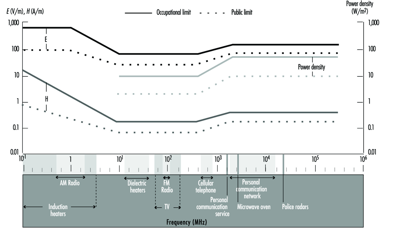
Standard C 95.1, set in 1991, by the IEEE gives limiting values for occupational exposure (controlled environment) of 0.4 W/kg for the average SAR over a person’s entire body, and 8 W/kg for the peak SAR delivered to any one gram of tissue for 6 minutes or more. The corresponding values for exposure to the general public (uncontrolled environment) are 0.08 W/kg for whole-body SAR and 1.6 W/kg for peak SAR. The body-to-ground current should not exceed 100 mA in a controlled environment and 45 mA in an uncontrolled environment. (See IEEE 1991 for further details.) The derived limits are shown in figure 2.
Figure 2. IEEE (1991) exposure limits for electric field strength E, magnetic field strength H and power density

Further information on radiofrequency fields and microwaves can be found in, for instance, Elder et al. 1989, Greene 1992, and Polk and Postow 1986.
VLF and ELF Electric and Magnetic Fields
Extremely low frequency (ELF) and very low frequency (VLF) electric and magnetic fields encompass the frequency range above static (> 0 Hz) fields up to 30 kHz. For this paper ELF is defined as being in the frequency range > 0 to 300 Hz and VLF in the range > 300 Hz to 30 kHz. In the frequency range > 0 to 30 kHz, the wavelengths vary from ∞(infinity) to 10 km and so the electric and magnetic fields act essentially independently of each other and must be treated separately. The electric field strength (E) is measured in volts per metre (V/m), the magnetic field strength (H) is measured in amperes per metre (A/m) and the magnetic flux density (B) in tesla (T).
Considerable debate about possible adverse health effects has been expressed by workers using equipment that operates in this frequency range. By far the most common frequency is 50/60 Hz, used for the generation, distribution and use of electric power. Concerns that exposure to 50/60 Hz magnetic fields may be associated with an increased cancer incidence have been fuelled by media reports, distribution of misinformation and ongoing scientific debate (Repacholi 1990; NRC 1996).
The purpose of this article is to provide an overview of the following topic areas:
- sources, occupations and applications
- dosimetry and measurement
- interaction mechanisms and biological effects
- human studies and effects on health
- protective measures
- occupational exposure standards.
Summary descriptions are provided to inform workers of the types and strengths of fields from major sources of ELF and VLF, biological effects, possible health consequences and current exposure limits. An outline of safety precautions and protective measures is also given. While many workers use visual display units (VDUs), only brief details are given in this article since they are covered in greater detail elsewhere in the Encyclopaedia.
Much of the material contained here can be found in greater detail in a number of recent reviews (WHO 1984, 1987, 1989, 1993; IRPA 1990; ILO 1993; NRPB 1992, 1993; IEEE 1991; Greene 1992; NRC 1996).
Sources of Occupational Exposure
Levels of occupational exposure vary considerably and are strongly dependent upon the particular application. Table 1 gives a summary of typical applications of frequencies in the range > 0 to 30 kHz.
Table 1. Applications of equipment operating in the range > 0 to 30 kHz
|
Frequency |
Wavelength(km) |
Typical applications |
|
16.67, 50, 60 Hz |
18,000–5,000 |
Power generation, transmissions and use, electrolytic processes, induction heating, arc and ladle furnaces, welding, transportation, etc., any industrial, commercial, medical or research use of electric power |
|
0.3–3 kHz |
1,000–100 |
Broadcast modulation, medical applications, electric furnaces, induction heating, hardening, soldering, melting, refining |
|
3–30 kHz |
100–10 |
Very long-range communications, radio navigation, broadcast modulation, medical applications, induction heating, hardening, soldering, melting, refining, VDUs |
Power generation and distribution
The principal artificial sources of 50/60 Hz electric and magnetic fields are those involved in power generation and distribution, and any equipment using electric current. Most such equipment operates at the power frequencies of 50 Hz in most countries and 60 Hz in North America. Some electric train systems operate at 16.67 Hz.
High voltage (HV) transmission lines and substations have associated with them the strongest electric fields to which workers may be routinely exposed. Conductor height, geometrical configuration, lateral distance from the line, and the voltage of the transmission line are by far the most significant factors in considering the maximum electric field strength at ground level. At lateral distances of about twice the line height, the electric field strength decreases with distance in an approximately linear fashion (Zaffanella and Deno 1978). Inside buildings near HV transmission lines, the electric field strengths are typically lower than the unperturbed field by a factor of about 100,000, depending on the configuration of the building and the structural materials.
Magnetic field strengths from overhead transmission lines are usually relatively low compared to industrial applications involving high currents. Electrical utility employees working in substations or on the maintenance of live transmission lines form a special group exposed to larger fields (of 5 mT and higher in some cases). In the absence of ferromagnetic materials, the magnetic field lines form concentric circles around the conductor. Apart from the geometry of the power conductor, the maximum magnetic flux density is determined only by the magnitude of the current. The magnetic field beneath HV transmission lines is directed mainly transverse to the line axis. The maximum flux density at ground level may be under the centre line or under the outer conductors, depending on the phase relationship between the conductors. The maximum magnetic flux density at ground level for a typical double circuit 500 kV overhead transmission lines system is approximately 35 μT per kiloampere of current transmitted (Bernhardt and Matthes 1992). Typical values for the magnetic flux density up to 0.05 mT occur in workplaces near overhead lines, in substations and in power stations operating at frequencies of 16 2/3, 50, or 60 Hz (Krause 1986).
Industrial processes
Occupational exposure to magnetic fields comes predominantly from working near industrial equipment using high currents. Such devices include those used in welding, electroslag refining, heating (furnaces, induction heaters) and stirring.
Surveys on induction heaters used in industry, performed in Canada (Stuchly and Lecuyer 1985), in Poland (Aniolczyk 1981), in Australia (Repacholi, unpublished data) and in Sweden (Lövsund, Oberg and Nilsson 1982), show magnetic flux densities at operator locations ranging from 0.7 μT to 6 mT, depending on the frequency used and the distance from the machine. In their study of magnetic fields from industrial electro-steel and welding equipment, Lövsund, Oberg and Nilsson (1982) found that spot-welding machines (50 Hz, 15 to 106 kA) and ladle furnaces (50 Hz, 13 to 15 kA) produced fields up to 10 mT at distances up to 1 m. In Australia, an induction heating plant operating in the range 50 Hz to 10 kHz was found to give maximum fields of up to 2.5 mT (50 Hz induction furnaces) at positions where operators could stand. In addition maximum fields around induction heaters operating at other frequencies were 130 μT at 1.8 kHz, 25 μT at 2.8 kHz and in excess of 130 μT at 9.8 kHz.
Since the dimensions of coils producing the magnetic fields are often small there is seldom high exposure to the whole body, but rather local exposure mainly to the hands. Magnetic flux density to the hands of the operator may reach 25 mT (Lövsund and Mild 1978; Stuchly and Lecuyer 1985). In most cases the flux density is less than 1 mT. The electric field strength near the induction heater is usually low.
Workers in the electrochemical industry may be exposed to high electric and magnetic field strengths because of electrical furnaces or other devices using high currents. For instance, near induction furnaces and industrial electrolytic cells magnetic flux densities can be measured as high as 50 mT.
Visual display units
The use of visual display units (VDUs) or video display terminals (VDTs) as they are also called, grows at an ever increasing rate. VDT operators have expressed concerns about possible effects from emissions of low-level radiations. Magnetic fields (frequency 15 to 125 kHz) as high as 0.69 A/m (0.9 μT) have been measured under worst-case conditions close to the surface of the screen (Bureau of Radiological Health 1981). This result has been confirmed by many surveys (Roy et al. 1984; Repacholi 1985 IRPA 1988). Comprehensive reviews of measurements and surveys of VDTs by national agencies and individual experts concluded that there are no radiation emissions from VDTs that would have any consequences for health (Repacholi 1985; IRPA 1988; ILO 1993a). There is no need to perform routine radiation measurements since, even under worst-case or failure mode conditions, the emission levels are well below the limits of any international or national standards (IRPA 1988).
A comprehensive review of emissions, summary of the applicable scientific literature, standards and guidelines has been provided in the document (ILO 1993a).
Medical applications
Patients suffering from bone fractures that do not heal well or unite have been treated with pulsed magnetic fields (Bassett, Mitchell and Gaston 1982; Mitbreit and Manyachin 1984). Studies are also being conducted on the use of pulsed magnetic fields to enhance wound healing and tissue regeneration.
Various devices generating magnetic field pulses are used for bone growth stimulation. A typical example is the device that generates an average magnetic flux density of about 0.3 mT, a peak strength of about 2.5 mT, and induces peak electric field strengths in the bone in the range of 0.075 to 0.175 V/m (Bassett, Pawluk and Pilla 1974). Near the surface of the exposed limb, the device produces a peak magnetic flux density of the order of 1.0 mT causing peak ionic current densities of about 10 to 100 mA/m2 (1 to 10 μA/cm2) in tissue.
Measurement
Prior to the commencement of measurements of ELF or VLF fields, it is important to obtain as much information as possible about the characteristics of the source and the exposure situation. This information is required for the estimation of the expected field strengths and the selection of the most appropriate survey instrumentation (Tell 1983).
Information about the source should include:
- frequencies present, including harmonics
- power transmitted
- polarization (orientation of E field)
- modulation characteristics (peak and average values)
- duty cycle, pulse width, and pulse repetition frequency
- antenna characteristics, such as type, gain, beam width and scan rate.
Information about the exposure situation must include:
- distance from the source
- existence of any scattering objects. Scattering by plane surfaces can enhance the E field by a factor of 2. Even greater enhancement may result from curved surfaces, e.g., corner reflectors.
Results of surveys conducted in occupational settings are summarized in table 2.
Table 2. Occupational sources of exposure to magnetic fields
|
Source |
Magnetic flux |
Distance (m) |
|
VDTs |
Up to 2.8 x 10⁻⁴ |
0.3 |
|
HV lines |
Up to 0.4 |
under line |
|
Power stations |
Up to 0.27 |
1 |
|
Welding arcs (0–50 Hz) |
0.1–5.8 |
0–0.8 |
|
Induction heaters (50–10 kHz) |
0.9–65 |
0.1–1 |
|
50 Hz Ladle furnace |
0.2–8 |
0.5–1 |
|
50 Hz Arc furnace |
Up to 1 |
2 |
|
10 Hz Induction stirrer |
0.2–0.3 |
2 |
|
50 Hz Electroslag welding |
0.5–1.7 |
0.2–0.9 |
|
Therapeutic equipment |
1–16 |
1 |
Source: Allen 1991; Bernhardt 1988; Krause 1986; Lövsund, Oberg and Nilsson 1982; Repacholi, unpublished data; Stuchly 1986; Stuchly and Lecuyer 1985, 1989.
Instrumentation
An electric or magnetic field-measuring instrument consists of three basic parts: the probe, the leads and the monitor. To ensure appropriate measurements, the following instrumentation characteristics are required or are desirable:
- The probe must respond only to the E field or the H field and not to both simultaneously.
- The probe must not produce significant perturbation of the field.
- The leads from the probe to the monitor must not disturb the field at the probe significantly, or couple energy from the field.
- The frequency response of the probe must cover the range of frequencies required to be measured.
- If used in the reactive near-field, the dimensions of the probe sensor should preferably be less than a quarter of a wavelength at the highest frequency present.
- The instrument should indicate the root mean square (rms) value of the measured field parameter.
- The response time of the instrument should be known. It is desirable to have a response time of about 1 second or less, so that intermittent fields are easily detected.
- The probe should be responsive to all polarization components of the field. This may be accomplished either by inherent isotropic response, or by physical rotation of the probe through three orthogonal directions.
- Good overload protection, battery operation, portability and rugged construction are other desirable characteristics.
- Instruments provide an indication of one or more of the following parameters: average E field (V/m) or mean square E field (V2/m2); average H field (A/m) or mean square H field (A2/m2).
Surveys
Surveys are usually conducted to determine whether fields existing in the workplace are below limits set by national standards. Thus the person taking the measurements must be fully familiar with these standards.
All occupied and accessible locations should be surveyed. The operator of the equipment under test and the surveyor should be as far away as practicable from the test area. All objects normally present, which may reflect or absorb energy, must be in position. The surveyor should take precautions against radiofrequency (RF) burns and shock, particularly near high-power, low-frequency systems.
Interaction Mechanisms and Biological Effects
Interaction mechanisms
The only established mechanisms by which ELF and VLF fields interact with biological systems are:
- Electric fields which induce a surface charge on an exposed body which results in currents (measured in mA/m2) inside the body, the magnitude of which is related to the surface charge density. Depending on the exposure conditions, size, shape and position of the exposed body in the field, the surface charge density can vary greatly, resulting in a variable and non-uniform distribution of currents inside the body.
- Magnetic fields also act on humans by inducing electric fields and currents inside the body.
- Electric charges induced in a conducting object (e.g., an automobile) exposed to ELF or VLF electric fields may cause current to pass through a person in contact with it.
- Magnetic field coupling to a conductor (for example, a wire fence) causes electric currents (of the same frequency as the exposing field) to pass through the body of a person in contact with it.
- Transient discharges (sparks) can occur when people and metal objects exposed to a strong electric field come into sufficiently close proximity.
- Electric or magnetic fields may interfere with implanted medical devices (e.g., unipolar cardiac pacemakers) and cause malfunction of the device.
The first two interactions listed above are examples of direct coupling between persons and ELF or VLF fields. The last four interactions are examples of indirect coupling mechanisms because they can occur only when the exposed organism is in the vicinity of other bodies. These bodies can include other humans or animals and objects such as automobiles, fences or implanted devices.
While other mechanisms of interaction between biological tissues and ELF or VLF fields have been postulated or there is some evidence to support their existence (WHO 1993; NRPB 1993; NRC 1996), none has been shown to be responsible for any adverse consequence to health.
Health effects
The evidence suggests that most of the established effects of exposure to electric and magnetic fields in the frequency range > 0 to 30 kHz result from acute responses to surface charge and induced current density. People can perceive the effects of the oscillating surface charge induced on their bodies by ELF electric fields (but not by magnetic fields); these effects become annoying if sufficiently intense. A summary of the effects of currents passing through the human body (thresholds for perception, let-go or tetanus) are given in table 3.
Table 3. Effects of currents passing through the human body
|
Effect |
Subject |
Threshold current in mA |
||||
|
50 and 60 Hz |
300 Hz |
1000 Hz |
10 kHz |
30 kHz |
||
|
Perception |
Men Women Children |
1.1 0.7 0.55 |
1.3 0.9 0.65 |
2.2 1.5 1.1 |
15 10 9 |
50 35 30 |
|
Let-go threshold shock |
Men Women Children |
9 6 4.5 |
11.7 7.8 5.9 |
16.2 10.8 8.1 |
55 37 27 |
126 84 63 |
|
Thoracic tetanization; |
Men Women Children |
23 15 12 |
30 20 15 |
41 27 20.5 |
94 63 47 |
320 214 160 |
Source: Bernhardt 1988a.
Human nerve and muscle cells have been stimulated by the currents induced by exposure to magnetic fields of several mT and 1 to 1.5 kHz; threshold current densities are thought to be above 1 A/m2. Flickering visual sensations can be induced in the human eye by exposure to magnetic fields as low as about 5 to 10 mT (at 20 Hz) or electric currents directly applied to the head. Consideration of these responses and of the results of neurophysiological studies suggests that subtle central nervous system functions, such as reasoning or memory, may be affected by current densities above 10 mA/m2 (NRPB 1993). Threshold values are likely to remain constant up to about 1 kHz but rise with increasing frequency thereafter.
Several in vitro studies (WHO 1993; NRPB 1993) have reported metabolic changes, such as alterations in enzyme activity and protein metabolism and decreased lymphocyte cytotoxicity, in various cell lines exposed to ELF and VLF electric fields and currents applied directly to the cell culture. Most effects have been reported at current densities between about 10 and 1,000 mA/m2, although these responses are less clearly defined (Sienkiewicz, Saunder and Kowalczuk 1991). However, it is worth noting that the endogenous current densities generated by the electrical activity of nerves and muscles are typically as high as 1 mA/m2 and may reach up to 10 mA/m2 in the heart. These current densities will not adversely affect nerve, muscle and other tissues. Such biological effects will be avoided by restricting the induced current density to less than 10 mA/m2 at frequencies up to about 1 kHz.
Several possible areas of biological interaction which have many health implications and about which our knowledge is limited include: possible changes in night-time melatonin levels in the pineal gland and alterations in circadian rhythms induced in animals by exposure to ELF electric or magnetic fields, and possible effects of ELF magnetic fields on the processes of development and carcinogenesis. In addition, there is some evidence of biological responses to very weak electric and magnetic fields: these include the altered mobility of calcium ions in brain tissue, changes in neuronal firing patterns, and altered operand behaviour. Both amplitude and frequency “windows” have been reported which challenge the conventional assumption that the magnitude of a response increases with increasing dose. These effects are not well established and do not provide a basis for establishing restrictions on human exposure, although further investigations are warranted (Sienkievicz, Saunder and Kowalczuk 1991; WHO 1993; NRC 1996).
Table 4 gives the approximate ranges of induced current densities for various biological effects in humans.
Table 4. Approximate current density ranges for various biological effects
|
Effect |
Current density (mA/m2) |
|
Direct nerve and muscle stimulation |
1,000–10,000 |
|
Modulation in central nervous system activity |
100–1,000 |
|
Changes in retinal function |
|
|
Endogenous current density |
1–10 |
Source: Sienkiewicz et al. 1991.
Occupational Exposure Standards
Nearly all standards having limits in the range > 0-30 kHz have, as their rationale, the need to keep induced electric fields and currents to safe levels. Usually the induced current densities are restricted to less than 10 mA/m2. Table 5 gives a summary of some current occupational exposure limits.
Table 5. Occupational limits of exposure to electric and magnetic fields in the frequency range > 0 to 30 kHz (note that f is in Hz)
|
Country/Reference |
Frequency range |
Electric field (V/m) |
Magnetic field (A/m) |
|
International (IRPA 1990) |
50/60 Hz |
10,000 |
398 |
|
USA (IEEE 1991) |
3–30 kHz |
614 |
163 |
|
USA (ACGIH 1993) |
1–100 Hz 100–4,000 Hz 4–30 kHz |
25,000 2.5 x 10⁶/f 625 |
60/f 60/f 60/f |
|
Germany (1996) |
50/60 Hz |
10,000 |
1,600 |
|
UK (NRPB 1993) |
1–24 Hz 24–600 Hz 600–1,000 Hz 1–30 kHz |
25,000 6 x 10⁵/f 1,000 1,000 |
64,000/f 64,000/f 64,000/f 64 |
Protective Measures
Occupational exposures that occur near high voltage transmission lines depend on the worker’s location either on the ground or at the conductor during live-line work at high potential. When working under live-line conditions, protective clothing may be used to reduce the electric field strength and current density in the body to values similar to those that would occur for work on the ground. Protective clothing does not weaken the influence of the magnetic field.
The responsibilities for the protection of workers and the general public against the potentially adverse effects of exposure to ELF or VLF electric and magnetic fields should be clearly assigned. It is recommended that the competent authorities consider the following steps:
- development and adoption of exposure limits and the implementation of a compliance programme
- development of technical standards to reduce the susceptibility to electromagnetic interference, for example, for pacemakers
- development of standards defining zones with limited access around sources of strong electric and magnetic fields because of electromagnetic interference (e.g., for pacemakers and other implanted devices). The use of appropriate warning signs should be considered.
- requirement of specific assignment of a person responsible for the safety of workers and the public at each site with high exposure potentials
- development of standardized measurement procedures and survey techniques
- requirements for the education of workers on the effects of exposure to ELF or VLF electric and magnetic fields and the measures and rules which are designed to protect them
- drafting of guidelines or codes of practice for worker safety in ELF or VLF electric and magnetic fields. ILO (1993a) provides excellent guidance for such a code.
More...
Static Electric and Magnetic Fields
Both our natural and our artificial environments generate electric and magnetic forces of various magnitudes—in the outdoors, in offices, in households and in industrial workplaces. This raises two important questions: (1) do these exposures pose any adverse human health effects, and (2) what limits can be set in an attempt to define “safe” limits of such exposures?
This discussion focuses on static electric and magnetic fields. Studies are described on workers in various industries, and also on animals, which fail to demonstrate any clear-cut adverse biological effects at the levels of exposure to electric and magnetic fields usually encountered. Nevertheless, attempts are made to discuss the efforts of a number of international organizations to set guidelines to protect workers and others from any possible dangerous level of exposure.
Definition of Terms
When a voltage or electric current is applied to an object such as an electrical conductor, the conductor becomes charged and forces start to act on other charges in the vicinity. Two types of forces may be distinguished: those arising from stationary electric charges, known as the electrostatic force, and those appearing only when charges are moving (as in an electric current in a conductor), known as the magnetic force. To describe the existence and spatial distribution of these forces, physicists and mathematicians have created the concept of field. One thus speaks of a field of force, or simply, electric and magnetic fields.
The term static describes a situation where all charges are fixed in space, or move as a steady flow. As a result, both charges and current densities are constant in time. In the case of fixed charges, we have an electric field whose strength at any point in space depends on the value and geometry of all the charges. In the case of steady current in a circuit, we have both an electric and a magnetic field constant in time (static fields), since the charge density at any point of the circuit does not vary.
Electricity and magnetism are distinct phenomena as long as charges and current are static; any interconnection between electric and magnetic fields disappears in this static situation and thus they can be treated separately (unlike the situation in time-varying fields). Static electric and magnetic fields are clearly characterized by steady, time-independent strengths and correspond to the zero-frequency limit of the extremely low frequency (ELF) band.
Static Electric Fields
Natural and occupational exposure
Static electric fields are produced by electrically charged bodies where an electric charge is induced on the surface of an object within a static electric field. As a consequence, the electric field at the surface of an object, particularly where the radius is small, such as at a point, can be larger than the unperturbed electric field (that is, the field without the object present). The field inside the object may be very small or zero. Electric fields are experienced as a force by electrically charged objects; for example, a force will be exerted on body hair, which may be perceived by the individual.
On the average, the surface charge of the earth is negative while the upper atmosphere carries a positive charge. The resulting static electric field near the earth’s surface has a strength of about 130 V/m. This field decreases with height, and its value is about 100 V/m at 100 m elevation, 45 V/m at 1 km, and less than 1 V/m at 20 km. Actual values vary widely, depending upon the local temperature and humidity profile and the presence of ionized contaminants. Beneath thunderclouds, for example, and even as thunderclouds are approaching, large field variations occur at ground level, because normally the lower part of a cloud is negatively charged while the upper part contains a positive charge. In addition, there is a space charge between the cloud and ground. As the cloud approaches, the field at ground level may first increase and then reverse, with the ground becoming positively charged. During this process, fields of 100 V/m to 3 kV/m may be observed even in the absence of local lightning; field reversals may take place very rapidly, within 1 min, and high field strengths may persist for the duration of the storm. Ordinary clouds, as well as thunderclouds, contain electric charges and therefore deeply affect the electric field at ground level. Large deviations from the fair-weather field, up to 200%, are also to be expected in the presence of fog, rain and naturally occurring small and large ions. Electric field changes during the daily cycle can even be expected in completely fair weather: fairly regular changes in local ionization, temperature or humidity and the resulting changes in the atmospheric electrical conductivity near the ground, as well as mechanical charge transfer by local air movements, are probably responsible for these diurnal variations.
Typical levels of man-made electrostatic fields are in the 1 to 20 kV/m range in offices and households; these fields are frequently generated around high-voltage equipment, such as TV sets and video display units (VDUs), or by friction. Direct current (DC) transmission lines generate both static electric and magnetic fields and are an economical means of power distribution where long distances are involved.
Static electric fields are widely used in industries such as chemicals, textile, aviation, paper and rubber, and in transportation.
Biological effects
Experimental studies provide little biological evidence to suggest any adverse effect of static electric fields on human health. The few animal studies that have been carried out also appear to have yielded no data supporting adverse effects on genetics, tumour growth, or on the endocrine or cardiovascular systems. (Table 1 summarizes these animal studies.)
Table 1. Studies on animals exposed to static electric fields
|
Biological end-points |
Reported effects |
Exposure conditions |
|
Haematology and immunology |
Changes in the albumin and globulin fractions of serum proteins in rats. No significant differences in blood cell counts, blood proteins or blood |
Continuous exposure to fields between 2.8 and 19.7 kV/m Exposure to 340 kV/m for 22 h/day for a total of 5,000 h |
|
Nervous system |
Induction of significant changes observed in the EEGs of rats. However, no clear indication of a consistent response No significant changes in the concentrations and utilization rates of |
Exposure to electric field strengths up to 10 kV/m Exposure to a 3 kV/m field for up to 66 h |
|
Behaviour |
Recent, well-conducted studies suggesting no effect on rodent Production of dose-dependent avoidance behaviour in male rats, with no influence of air ions |
Exposure to field strengths up to 12 kV/m Exposure to HVD electric fields ranging from 55 to 80 kV/m |
|
Reproduction and development |
No significant differences in the total number of offspring nor in the |
Exposure to 340 kV/m for 22 h/day before, during and after |
No in vitro studies have been conducted to evaluate the effect of exposing cells to static electric fields.
Theoretical calculations suggest that a static electric field will induce a charge on the surface of exposed people, which may be perceived if discharged to a grounded object. At a sufficiently high voltage, the air will ionize and become capable of conducting an electric current between, for example, a charged object and a grounded person. The breakdown voltage depends on a number of factors, including the shape of the charged object and atmospheric conditions. Typical values of corresponding electric field strengths range between 500 and 1,200 kV/m.
Reports from some countries indicate that a number of VDU operators have experienced skin disorders, but the exact relationship of these to VDU work is unclear. Static electric fields at VDU workplaces have been suggested as a possible cause of these skin disorders, and it is possible that the electrostatic charge of the operator may be a relevant factor. However, any relationship between electrostatic fields and skin disorders must still be regarded as hypothetical based on available research evidence.
Measurements, prevention, exposure standards
Static electric field strength measurements may be reduced to measurements of voltages or electric charges. Several electrostatic voltmeters are commercially available which permit accurate measurements of electrostatic or other high-impedance sources without physical contact. Some utilize an electrostatic chopper for low drift, and negative feedback for accuracy and probe-to-surface spacing insensitivity. In some cases the electrostatic electrode “looks” at the surface under measurement through a small hole at the base of the probe assembly. The chopped AC signal induced on this electrode is proportional to the differential voltage between the surface under measurement and the probe assembly. Gradient adapters are also used as accessories to electrostatic voltmeters, and permit their use as electrostatic field strength meters; direct readout in volts per metre of separation between the surface under test and the grounded plate of the adapter is possible.
There are no good data which can serve as guidelines to set base limits of human exposure to static electric fields. In principle, an exposure limit could be derived from the minimum breakdown voltage for air; however, the field strength experienced by a person within a static electric field will vary according to body orientation and shape, and this must be taken into account in attempting to arrive at an appropriate limit.
Threshold limit values (TLVs) have been recommended by the American Conference of Governmental Industrial Hygienists (ACGIH 1995). These TLVs refer to the maximum unprotected workplace static electric field strength, representing conditions under which nearly all workers may be exposed repeatedly without adverse health effects. According to ACGIH, occupational exposures should not exceed a static electric field strength of 25 kV/m. This value should be used as a guide in the control of exposure and, due to individual susceptibility, should not be regarded as a clear line between safe and dangerous levels. (This limit refers to the field strength present in air, away from the surfaces of conductors, where spark discharges and contact currents may pose significant hazards, and is intended for both partial-body and whole-body exposures.) Care should be taken to eliminate ungrounded objects, to ground such objects, or to use insulated gloves when ungrounded objects must be handled. Prudence dictates the use of protective devices (e.g., suits, gloves and insulation) in all fields exceeding 15 kV/m.
According to ACGIH, present information on human responses and possible health effects of static electric fields is insufficient to establish a reliable TLV for time-weighted average exposures. It is recommended that, lacking specific information from the manufacturer on electromagnetic interference, the exposure of wearers of pacemakers and other medical electronic devices should be maintained at or below 1 kV/m.
In Germany, according to a DIN Standard, occupational exposures should not exceed a static electric field strength of 40 kV/m. For short exposures (up to two hours per day) a higher limit of 60 kV/m is permitted.
In 1993, the National Radiological Protection Board (NRPB 1993) provided advice concerning appropriate restrictions on the exposure of people to electromagnetic fields and radiation. This includes both static electric and magnetic fields. In the NRPB document, investigation levels are provided for the purpose of comparing values of measured field quantities in order to determine whether or not compliance with basic restrictions has been achieved. If the field to which a person is exposed exceeds the relevant investigation level, compliance with the basic restrictions must be checked. Factors that might be considered in such an assessment include, for example, the efficiency of the coupling of the person to the field, the spatial distribution of the field across the volume occupied by the person, and the duration of exposure.
According to NRPB it is not possible to recommend basic restrictions for avoiding direct effects of human exposure to static electric fields; guidance is given to avoid annoying effects of direct perception of the surface electric charge and indirect effects such as electric shock. For most people, the annoying perception of surface electric charge, acting directly on the body, will not occur during exposure to static electric field strengths less than about 25 kV/m, that is, the same field strength recommended by ACGIH. To avoid spark discharges (indirect effects) causing stress, NRPB recommends that DC contact currents be restricted to less than 2 mA. Electric shock from low impedance sources can be prevented by following established electrical safety procedures relevant to such equipment.
Static Magnetic Fields
Natural and occupational exposure
The body is relatively transparent to static magnetic fields; such fields will interact directly with magnetically anisotropic materials (exhibiting properties with different values when measured along axes in different directions) and moving charges.
The natural magnetic field is the sum of an internal field due to the earth acting as a permanent magnet and an external field generated in the environment from such factors as solar activity or atmospherics. The internal magnetic field of the earth originates from the electric current flowing in the upper layer of the earth’s core. There are significant local differences in the strength of this field, whose average magnitude varies from about 28 A/m at the equator (corresponding to a magnetic flux density of about 35 mT in a non-magnetic material such as air) to about 56 A/m over the geomagnetic poles (corresponding to about 70 mT in air).
Artificial fields are stronger than those of natural origin by many orders of magnitude. Artificial sources of static magnetic fields include all devices containing wires carrying direct current, including many appliances and equipment in industry.
In direct-current power transmission lines, static magnetic fields are produced by moving charges (an electric current) in a two-wire line. For an overhead line, the magnetic flux density at ground level is about 20 mT for a 500 kV line. For an underground transmission line buried at 1.4 m and carrying a maximum current of about 1 kA, the maximum magnetic flux density is less than 10 mT at ground level.
Major technologies that involve the use of large static magnetic fields are listed in table 2 along with their corresponding exposure levels.
Table 2. Major technologies involving the use of large static magnetic fields, and corresponding exposure levels
|
Procedures |
Exposure levels |
|
Energy technologies |
|
|
Thermonuclear fusion reactors |
Fringe fields up to 50 mT in areas accessible to personnel. |
|
Magnetohydrodynamic systems |
Approximately 10 mT at about 50 m; 100 mT only at distances greater than 250 m |
|
Superconducting magnet energy storage systems |
Fringe fields up to 50 mT at operator-accessible locations |
|
Superconducting generators and transmission lines |
Fringe fields projected to be less than 100 mT |
|
Research facilities |
|
|
Bubble chambers |
During changes of film cassettes, the field is about 0.4–0.5 T at foot level and about 50 mT at the level of the head |
|
Superconducting spectrometers |
About 1 T at operator-accessible locations |
|
Particle accelerators |
Personnel are seldom exposed because of exclusion from the high radiation zone. Exceptions arise only during maintenance |
|
Isotope separation units |
Brief exposures to fields up to 50 mT |
|
Industry |
|
|
Aluminium production |
Levels up to 100 mT in operator-accessible locations |
|
Electrolytic processes |
Mean and maximum field levels of about 10 and 50 mT, respectively |
|
Production of magnets |
2–5 mT at worker’s hands; in the range of 300 to 500 mT at the level of the chest and head |
|
Medicine |
|
|
Nuclear magnetic resonance imaging and spectroscopy |
An unshielded 1-T magnet produces about 0.5 mT at 10 m, and an unshielded 2-T magnet produces the same exposure at about 13 m |
Biological effects
Evidence from experiments with laboratory animals indicates that there are no significant effects on the many developmental, behavioural, and physiological factors evaluated at static magnetic flux densities up to 2 T. Nor have studies on mice demonstrated any harm to the foetus from exposure to magnetic fields up to 1 T.
Theoretically, magnetic effects could retard blood flowing in a strong magnetic field and produce a rise in blood pressure. A flow reduction of at most a few per cent could be expected at 5 T, but none was observed in human subjects at 1.5 T, when investigated.
Some studies on workers involved in the manufacture of permanent magnets have reported various subjective symptoms and functional disturbances: irritability, fatigue, headache, loss of appetite, bradycardia (slow heart beat), tachycardia (rapid heart beat), decreased blood pressure, altered EEG, itching, burning and numbness. However, lack of any statistical analysis or assessment of the impact of physical or chemical hazards in the working environment significantly reduces the validity of these reports and makes them difficult to evaluate. Although the studies are inconclusive, they do suggest that, if long-term effects do in fact occur, they are very subtle; no cumulative gross effects have been reported.
Individuals exposed to a 4T magnetic flux density have been reported as experiencing sensory effects associated with motion in the field, such as vertigo (dizziness), feeling of nausea, a metallic taste, and magnetic sensations when moving the eyes or head. However, two epidemiological surveys of general health data in workers chronically exposed to static magnetic fields failed to reveal any significant health effects. Health data of 320 workers were obtained in plants using large electrolytic cells for chemical separation processes where the average static field level in the work environment was 7.6 mT and the maximum field was 14.6 mT. Slight changes in the white blood cell count, but still within the normal range, were detected in the exposed group compared to the 186 controls. None of the observed transient changes in blood pressure or other blood measurements was considered indicative of a significant adverse effect associated with magnetic field exposure. In another study, the prevalence of disease was evaluated among 792 workers who were occupationally exposed to static magnetic fields. The control group consisted of 792 unexposed workers matched for age, race and socio-economic status. The range of magnetic field exposures varied from 0.5 mT for long durations to 2 T for periods of several hours. No statistically significant change in the prevalence of 19 categories of disease was observed in the exposed group compared with the controls. No difference in the prevalence of disease was found between a subgroup of 198 who had experienced exposures of 0.3 T or higher for periods of one hour or longer when compared with the remainder of the exposed population or the matched controls.
A report on workers in the aluminium industry indicated an elevated leukaemia mortality rate. Although this epidemiological study reported an increased cancer risk for persons directly involved in aluminium production where workers are exposed to large static magnetic fields, there is at present no clear evidence to indicate exactly which carcinogenic factors within the work environment are responsible. The process used for aluminium reduction creates coal tar, pitch volatiles, fluoride fumes, sulphur oxides and carbon dioxide, and some of these might be more likely candidates for cancer-causing effects than magnetic field exposure.
In a study on French aluminium workers, cancer mortality and mortality from all causes were found not to differ significantly from that observed for the general male population of France (Mur et al. 1987).
Another negative finding linking magnetic field exposures to possible cancer outcomes comes from a study of a group of workers at a chloroalkali plant where the 100 kA DC currents used for the electrolytic production of chlorine gave rise to static magnetic flux densities, at worker’s locations, ranging from 4 to 29 mT. The observed versus expected incidence of cancer among these workers over a 25-year period showed no significant differences.
Measurements, prevention and exposure standards
During the last thirty years, the measurement of magnetic fields has undergone considerable development. Progress in techniques has made it possible to develop new methods of measurement as well as to improve old ones.
The two most popular types of magnetic field probes are a shielded coil and a Hall probe. Most of the commercially available magnetic field meters use one of them. Recently, other semiconductor devices, namely bipolar transistors and FET transistors, have been proposed as magnetic field sensors. They offer some advantages over Hall probes, such as higher sensitivity, greater spatial resolution and broader frequency response.
The principle of the nuclear magnetic resonance (NMR) measurement technique is to determine the resonant frequency of the test specimen in the magnetic field to be measured. It is an absolute measurement that can be made with very great accuracy. The measuring range of this method is from about 10 mT to 10 T, with no definite limits. In field measurements using the proton magnetic resonance method, an accuracy of 10–4 is easily obtained with simple apparatus and an accuracy of 10–6 can be reached with extensive precautions and refined equipment. The inherent shortcoming of the NMR method is its limitation to a field with a low gradient and the lack of information about the field direction.
Recently, several personal dosimeters suitable for monitoring exposures to static magnetic fields have also been developed.
Protective measures for the industrial and scientific use of magnetic fields can be categorized as engineering design measures, the use of separation distance, and administrative controls. Another general category of hazard-control measures, which include personal protective equipment (e.g., special garments and face masks), does not exist for magnetic fields. However, protective measures against potential hazards from magnetic interference with emergency or medical electronic equipment and for surgical and dental implants are a special area of concern. The mechanical forces imparted to ferromagnetic (iron) implants and loose objects in high-field facilities require that precautions be taken to guard against health and safety hazards.
Techniques to minimize undue exposure to high-intensity magnetic fields around large research and industrial facilities generally fall into four types:
- distance and time
- magnetic shielding
- electromagnetic interference (EMI) and compatibility
- administrative measures.
The use of warning signs and special-access areas to limit exposure of personnel near large magnet facilities has been of greatest use for controlling exposure. Administrative controls such as these are generally preferable to magnetic shielding, which can be extremely expensive. Loose ferromagnetic and paramagnetic (any magnetizing substances) objects can be converted into dangerous missiles when subjected to intense magnetic field gradients. Avoidance of this hazard can be achieved only by removing loose metallic objects from the area and from personnel. Such items as scissors, nail files, screwdrivers and scalpels should be banned from the immediate vicinity.
The earliest static magnetic field guidelines were developed as an unofficial recommendation in the former Soviet Union. Clinical investigations formed the basis for this standard, which suggested that the static magnetic field strength at the workplace should not exceed 8 kA/m (10 mT).
The American Conference of Governmental Industrial Hygienists issued TLVs of static magnetic flux densities that most workers could be exposed to repeatedly, day after day, without adverse health effects. As for electric fields, these values should be used as guides in the control of exposure to static magnetic fields, but they should not be regarded as a sharp line between safe and dangerous levels. According to ACGIH, routine occupational exposures should not exceed 60 mT averaged over the whole body or 600 mT to the extremities on a daily, time-weighted basis. A flux density of 2 T is recommended as a ceiling value. Safety hazards may exist from the mechanical forces exerted by the magnetic field upon ferromagnetic tools and medical implants.
In 1994, the International Commission on Non-Ionizing Radiation Protection (ICNIRP 1994) finalized and published guidelines on limits of exposure to static magnetic fields. In these guidelines, a distinction is made between exposure limits for workers and the general public. The limits recommended by the ICNIRP for occupational and general public exposures to static magnetic fields are summarized in table 3. When magnetic flux densities exceed 3 mT, precautions should be taken to prevent hazards from flying metallic objects. Analogue watches, credit cards, magnetic tapes and computer disks may be adversely affected by exposure to 1 mT, but this is not seen as a safety concern for people.
Table 3. Limits of exposure to static magnetic fields recommended by the International Commission on Non-Ionizing Radiation Protection (ICNIRP)
|
Exposure characteristics |
Magnetic flux density |
|
Occupational |
|
|
Whole working day (time-weighted average) |
200 mT |
|
Ceiling value |
2 T |
|
Limbs |
5 T |
|
General Public |
|
|
Continuous exposure |
40 mT |
Occasional access of the public to special facilities where magnetic flux densities exceed 40 mT can be allowed under appropriately controlled conditions, provided that the appropriate occupational exposure limit is not exceeded.
ICNIRP exposure limits have been set for a homogeneous field. For inhomogeneous fields (variations within the field), the average magnetic flux density must be measured over an area of 100 cm2.
According to a recent NRPB document, the restriction on acute exposure to less than 2 T will avoid acute responses such as vertigo or nausea and adverse health effects resulting from cardiac arrhythmia (irregular heart beat) or impaired mental function. In spite of the relative lack of evidence from studies of exposed populations regarding possible long-term effects of high fields, the Board considers it advisable to restrict long-term, time-weighted exposure over 24 hours to less than 200 mT (one-tenth of that intended to prevent acute responses). These levels are quite similar to those recommended by ICNIRP; ACGIH TLVs are slightly lower.
People with cardiac pacemakers and other electrically activated implanted devices, or with ferromagnetic implants, may not be adequately protected by the limits given here. The majority of cardiac pacemakers are unlikely to be affected from exposure to fields below 0.5 mT. People with some ferromagnetic implants or electrically activated devices (other than cardiac pacemakers) may be affected by fields above a few mT.
Other sets of guidelines recommending limits of occupational exposure exist: three of these are enforced in high-energy physics laboratories (Stanford Linear Accelerator Center and Lawrence Livermore National Laboratory in California, CERN accelerator laboratory in Geneva), and an interim guideline at the US Department of Energy (DOE).
In Germany, according to a DIN Standard, occupational exposures should not exceed a static magnetic field strength of 60 kA/m (about 75 mT). When only the extremities are exposed, this limit is set at 600 kA/m; field strength limits up to 150 kA/m are permitted for short, whole-body exposures (up to 5 min per hour).
Vibration
Vibration is oscillatory motion. This chapter summarizes human responses to whole-body vibration, hand-transmitted vibration and the causes of motion sickness.
Whole-body vibration occurs when the body is supported on a surface which is vibrating (e.g., when sitting on a seat which vibrates, standing on a vibrating floor or recumbent on a vibrating surface). Whole-body vibration occurs in all forms of transport and when working near some industrial machinery.
Hand-transmitted vibration is the vibration that enters the body through the hands. It is caused by various processes in industry, agriculture, mining and construction where vibrating tools or workpieces are grasped or pushed by the hands or fingers. Exposure to hand-transmitted vibration can lead to the development of several disorders.
Motion sickness can be caused by low frequency oscillation of the body, some types of rotation of the body and movement of displays relative to the body.
Magnitude
Oscillatory displacements of an object involve alternately a velocity in one direction and then a velocity in the opposite direction. This change of velocity means that the object is constantly accelerating, first in one direction and then in the opposite direction. The magnitude of a vibration can be quantified by its displacement, its velocity or its acceleration. For practical convenience, the acceleration is usually measured with accelerometers. The units of acceleration are metres per second per second (m/s2). The acceleration due to the Earth’s gravity is approximately 9.81 m/s2.
The magnitude of an oscillation can be expressed as the distance between the extremities reached by the motion (the peak-to-peak value) or the distance from some central point to the maximum deviation (the peak value). Often, the magnitude of vibration is expressed in terms of an average measure of the acceleration of the oscillatory motion, usually the root-mean-square value (m/s2 r.m.s.). For a single frequency (sinusoidal) motion, the r.m.s. value is the peak value divided by √2.
For a sinusoidal motion the acceleration, a (in m/s2), can be calculated from the frequency, f (in cycles per second), and the displacement, d (in metres):
a=(2πf)2d
This expression may be used to convert acceleration measurements to displacements, but it is only accurate when the motion occurs at a single frequency.
Logarithmic scales for quantifying vibration magnitudes in decibels are sometimes used. When using the reference level in International Standard 1683, the acceleration level, La, is expressed by La = 20 log10(a/a0), where a is the measured acceleration (in m/s2 r.m.s.) and a0 is the reference level of 10-6 m/s2. Other reference levels are used in some countries.
Frequency
The frequency of vibration, which is expressed in cycles per second (hertz, Hz), affects the extent to which vibration is transmitted to the body (e.g., to the surface of a seat or the handle of a vibratory tool), the extent to which it is transmitted through the body (e.g., from the seat to the head), and the effect of vibration in the body. The relation between the displacement and the acceleration of a motion are also dependent on the frequency of oscillation: a displacement of one millimetre corresponds to a very low acceleration at low frequencies but a very high acceleration at high frequencies; the vibration displacement visible to the human eye does not provide a good indication of vibration acceleration.
The effects of whole-body vibration are usually greatest at the lower end of the range, from 0.5 to 100 Hz. For hand-transmitted vibration, frequencies as high as 1,000 Hz or more may have detrimental effects. Frequencies below about 0.5 Hz can cause motion sickness.
The frequency content of vibration can be shown in spectra. For many types of whole-body and hand-transmitted vibration the spectra are complex, with some motion occurring at all frequencies. Nevertheless, there are often peaks, which show the frequencies at which most of the vibration occurs.
Since human responses to vibration vary according to the vibration frequency, it is necessary to weight the measured vibration according to how much vibration occurs at each frequency. Frequency weightings reflect the extent to which vibration causes the undesired effect at each frequency. Weightings are required for each axis of vibration. Different frequency weightings are required for whole-body vibration, hand-transmitted vibration and motion sickness.
Direction
Vibration may take place in three translational directions and three rotational directions. For seated persons, the translational axes are designated x-axis (fore-and-aft), y-axis (lateral) and
z-axis (vertical). Rotations about the x-, y- and z-axes are designated rx (roll), ry (pitch) and rz (yaw), respectively. Vibration is usually measured at the interfaces between the body and the vibration. The principal coordinate systems for measuring vibration with respect to whole-body and hand-transmitted vibration are illustrated in the next two articles in the chapter.
Duration
Human responses to vibration depend on the total duration of vibration exposure. If the characteristics of vibration do not change with time, the root-mean-square vibration provides a convenient measure of the average vibration magnitude. A stopwatch may then be sufficient to assess the exposure duration. The severity of the average magnitude and total duration can be assessed by reference to the standards in the following articles.
If the vibration characteristics vary, the measured average vibration will depend on the period over which it is measured. Furthermore, root-mean-square acceleration is believed to underestimate the severity of motions which contain shocks, or are otherwise highly intermittent.
Many occupational exposures are intermittent, vary in magnitude from moment to moment or contain occasional shocks. The severity of such complex motions can be accumulated in a manner which gives appropriate weight to, for example, short periods of high magnitude vibration and long periods of low magnitude vibration. Different methods of calculating doses are used (see “Whole-body vibration”; “Hand-transmitted vibration”; and “Motion sickness” in this chapter).
Whole-Body Vibration
Occupational Exposure
Occupational exposures to whole-body vibration mainly occur in transport but also in association with some industrial processes. Land, sea and air transport can all produce vibration that can cause discomfort, interfere with activities or cause injury. Table 1 lists some environments which may be most likely to be associated with a health risk.
Table 1. Activities for which it may be appropriate to warn of the adverse effects of whole-body vibration
Tractor driving
Armoured fighting vehicles (e.g., tanks) and similar vehicles
Other off-road vehicles:
Earth-moving machinery—loaders, excavators, bulldozers, graders,
- scrapers, dumpers, rollers
- Forest machines
- Mine and quarry equipment
- Forklift trucks
Some truck driving (articulated and non-articulated)
Some bus and tram driving
Some helicopter and fixed-wing aircraft flying
Some workers with concrete production machinery
Some railway drivers
Some use of high-speed marine craft
Some motor bicycle riding
Some car and van driving
Some sports activities
Some other industrial equipment
Source: Adapted from Griffin 1990.
The most common exposure to severe vibration and shocks may occur on off-road vehicles, including earth moving machinery, industrial trucks and agricultural tractors.
Biodynamics
Like all mechanical structures, the human body has resonance frequencies where the body exhibits a maximum mechanical response. Human responses to vibration cannot be explained solely in terms of a single resonance frequency. There are many resonances in the body, and the resonance frequencies vary among people and with posture. Two mechanical responses of the body are often used to describe the manner in which vibration causes the body to move: transmissibility and impedance.
The transmissibility shows the fraction of the vibration which is transmitted from, say, the seat to the head. The transmissibility of the body is highly dependent on vibration frequency, vibration axis and body posture. Vertical vibration on a seat causes vibration in several axes at the head; for vertical head motion, the transmissibility tends to be greatest in the approximate range of 3 to 10 Hz.
The mechanical impedance of the body shows the force that is required to make the body move at each frequency. Although the impedance depends on body mass, the vertical impedance of the human body usually shows a resonance at about 5 Hz. The mechanical impedance of the body, including this resonance, has a large effect on the manner in which vibration is transmitted through seats.
Acute Effects
Discomfort
The discomfort caused by vibration acceleration depends on the vibration frequency, the vibration direction, the point of contact with the body, and the duration of vibration exposure. For vertical vibration of seated persons, the vibration discomfort caused by any frequency increases in proportion to the vibration magnitude: a halving of the vibration will tend to halve the vibration discomfort.
The discomfort produced by vibration may be predicted by the use of appropriate frequency weightings (see below) and described by a semantic scale of discomfort. There are no useful limits for vibration discomfort: the acceptable discomfort varies from one environment to another.
Acceptable magnitudes of vibration in buildings are close to vibration perception thresholds. The effects on humans of vibration in buildings are assumed to depend on the use of the building in addition to the vibration frequency, direction and duration. Guidance on the evaluation of building vibration is given in various standards such as British Standard 6472 (1992) which defines a procedure for the evaluation of both vibration and shock in buildings.
Activity interference
Vibration can impair the acquisition of information (e.g., by the eyes), the output of information (e.g., by hand or foot movements) or the complex central processes that relate input to output (e.g., learning, memory, decision-making). The greatest effects of whole-body vibration are on input processes (mainly vision) and output processes (mainly continuous hand control).
Effects of vibration on vision and manual control are primarily caused by the movement of the affected part of the body (i.e., eye or hand). The effects may be decreased by reducing the transmission of vibration to the eye or to the hand, or by making the task less susceptible to disturbance (e.g., increasing the size of a display or reducing the sensitivity of a control). Often, the effects of vibration on vision and manual control can be much reduced by redesign of the task.
Simple cognitive tasks (e.g., simple reaction time) appear to be unaffected by vibration, other than by changes in arousal or motivation or by direct effects on input and output processes. This may also be true for some complex cognitive tasks. However, the sparsity and diversity of experimental studies does not exclude the possibility of real and significant cognitive effects of vibration. Vibration may influence fatigue, but there is little relevant scientific evidence, and none which supports the complex form of the “fatigue-decreased proficiency limit” offered in International Standard 2631 (ISO 1974, 1985).
Changes in Physiological Functions
Changes in physiological functions occur when subjects are exposed to a novel whole-body vibration environment in laboratory conditions. Changes typical of a “startle response” (e.g., increased heart rate) normalize quickly with continuing exposure, whereas other reactions either proceed or develop gradually. The latter can depend on all characteristics of vibration including the axis, the magnitude of acceleration, and the kind of vibration (sinusoidal or random), as well as on further variables such as circadian rhythm and characteristics of the subjects (see Hasan 1970; Seidel 1975; Dupuis and Zerlett 1986). Changes of physiological functions under field conditions often cannot be related to vibration directly, since vibration is often acting together with other significant factors, such as high mental strain, noise and toxic substances. Physiological changes are frequently less sensitive than psychological reactions (e.g., discomfort). If all available data on persistent physiological changes are summarized with respect to their first significant appearance depending on the magnitude and frequency of whole-body vibration, there is a boundary with a lower border around 0.7 m/s2 r.m.s. between 1 and 10 Hz, and rising up to 30 m/s2 r.m.s. at 100 Hz. Many animal studies have been performed, but their relevance to humans is doubtful.
Neuromuscular changes
During active natural motion, motor control mechanisms act as a feed-forward control that is constantly adjusted by additional feedback from sensors in muscles, tendons and joints. Whole-body vibration causes a passive artificial motion of the human body, a condition that is fundamentally different from the self-induced vibration caused by locomotion. The missing feed-forward control during whole-body vibration is the most distinct change of the normal physiological function of the neuromuscular system. The broader frequency range associated with whole-body vibration (between 0.5 and 100 Hz) compared to that for natural motion (between 2 and 8 Hz for voluntary movements, and below 4 Hz for locomotion) is a further difference that helps to explain reactions of the neuromuscular control mechanisms at very low and at high frequencies.
Whole-body vibration and transient acceleration cause an acceleration-related alternating activity in the electromyogram (EMG) of superficial back muscles of seated persons that requires a tonic contraction to be maintained. This activity is supposed to be of a reflex-like nature. It usually disappears completely if the vibrated subjects sit relaxed in a bent position. The timing of muscle activity depends on the frequency and magnitude of acceleration. Electromyographic data suggest that an increased spinal load can occur due to reduced muscular stabilization of the spine at frequencies from 6.5 to 8 Hz and during the initial phase of a sudden upward displacement. In spite of weak EMG activity caused by whole-body vibration, back muscle fatigue during vibration exposure can exceed that observed in normal sitting postures without whole-body vibration.
Tendon reflexes may be diminished or disappear temporarily during exposure to sinusoidal whole-body vibration at frequencies above 10 Hz. Minor changes of postural control after exposure to whole-body vibration are quite variable, and their mechanisms and practical significance are not certain.
Cardiovascular, respiratory, endocrine and metabolic changes
The observed changes persisting during exposure to vibration have been compared to those during moderate physical work (i.e., increases of heart rate, blood pressure and oxygen consumption) even at a vibration magnitude near to the limit of voluntary tolerance. The increased ventilation is partially caused by oscillations of the air in the respiratory system. Respiratory and metabolic changes may not correspond, possibly suggesting a disturbance of the respiration control mechanisms. Various and partially contradictory findings have been reported for changes of the adrenocorticotropic hormones (ACTH) and catecholamines.
Sensory and central nervous changes
Changes of vestibular function due to whole-body vibration have been claimed on the basis of an affected regulation of posture, although posture is controlled by a very complex system in which a disturbed vestibular function can be largely compensated by other mechanisms. Changes of the vestibular function seem to gain significance for exposures with very low frequencies or those near the resonance of the whole body. A sensory mismatch between vestibular, visual and proprioceptive (stimuli received within the tissues) information is supposed to be an important mechanism underlying physiological responses to some artificial motion environments.
Experiments with short-term and prolonged combined exposures to noise and whole-body vibration, seem to suggest that vibration has a minor synergistic effect on hearing. As a tendency, high intensities of whole-body vibration at 4 or 5 Hz were associated with higher additional temporary threshold shifts (TTS). There was no obvious relation between the additional TTS and exposure time. The additional TTS seemed to increase with higher doses of whole-body vibration.
Impulsive vertical and horizontal vibrations evoke brain potentials. Changes of the function of the human central nervous system have also been detected using auditory evoked brain potentials (Seidel et al. 1992). The effects were influenced by other environmental factors (e.g., noise), the difficulty of the task, and by the internal state of the subject (e.g., arousal, degree of attention towards the stimulus).
Long-Term Effects
Spinal health risk
Epidemiological studies have frequently indicated an elevated health risk for the spine in workers exposed for many years to intense whole-body vibration (e.g., work on tractors or earth-moving machines). Critical surveys of the literature have been prepared by Seidel and Heide (1986), Dupuis and Zerlett (1986) and Bongers and Boshuizen (1990). These reviews concluded that intense long-term whole-body vibration can adversely affect the spine and can increase the risk of low-back pain. The latter may be a secondary consequence of a primary degenerative change of the vertebrae and disks. The lumbar part of the vertebral column was found to be the most frequently affected region, followed by the thoracic region. A high rate of impairments of the cervical part, reported by several authors, seems to be caused by a fixed unfavourable posture rather than by vibration, although there is no conclusive evidence for this hypothesis. Only a few studies have considered the function of back muscles and found a muscular insufficiency. Some reports have indicated a significantly higher risk of the dislocation of lumbar disks. In several cross-sectional studies Bongers and Boshuizen (1990) found more low-back pain in drivers and helicopter pilots than in comparable reference workers. They concluded that professional vehicle driving and helicopter flying are important risk factors for low-back pain and back disorder. An increase in disability pensioning and long-term sick leave due to intervertebral disc disorders was observed among crane operators and tractor drivers.
Due to incomplete or missing data on exposure conditions in epidemiological studies, exact exposure-effect relationships have not been obtained. The existing data do not permit the substantiation of a no-adverse-effect level (i.e., safe limit) so as to reliably prevent diseases of the spine. Many years of exposure below or near the exposure limit of the current International Standard 2631 (ISO 1985) are not without risk. Some findings have indicated an increasing health risk with increased duration of exposure, although selection processes have made it difficult to detect a relation in the majority of studies. Thus, a dose-effect relationship cannot currently be established by epidemiological investigations. Theoretical considerations suggest marked detrimental effects of high peak loads acting on the spine during exposures with high transients. The use of an “energy equivalent” method to calculate a vibration dose (as in International Standard 2631 (ISO 1985)) is therefore questionable for exposures to whole-body vibration containing high peak accelerations. Different long-term effects of whole-body vibration depending on the vibration frequency have not been derived from epidemiological studies. Whole-body vibration at 40 to 50 Hz applied to standing workers through the feet was followed by degenerative changes of the bones of the feet.
In general, differences between subjects have been largely neglected, although selection phenomena suggest they may be of major importance. There are no clear data showing whether the effects of whole-body vibration on the spine depend on gender.
The general acceptance of degenerative disorders of the spine as an occupational disease is debated. Specific diagnostic features are not known which would permit a reliable diagnosis of the disorder as an outcome of exposure to whole-body vibration. A high prevalence of degenerative spinal disorders in non-exposed populations hinders the assumption of a predominantly occupational aetiology in individuals exposed to whole-body vibration. Individual constitutional risk factors that might modify vibration-induced strain are unknown. The use of a minimal intensity and/or a minimal duration of whole-body vibration as a prerequisite for the recognition of an occupational disease would not take into account the expected considerable variability in individual susceptibility.
Other health risks
Epidemiological studies suggest that whole-body vibration is one factor within a causative set of factors which contribute to other health risks. Noise, high mental strain and shift work are examples of important concomitant factors which are known to be associated with health disorders. The results of investigations into disorders of other bodily systems have often been divergent or have indicated a paradoxical dependence of the prevalence of pathology on the magnitude of whole-body vibration (i.e., a higher prevalence of adverse effects with a lower intensity). A characteristic complex of symptoms and pathological changes of the central nervous system, the musculo-skeletal system and the circulatory system has been observed in workers standing on machines used for the vibro-compression of concrete and exposed to whole-body vibration beyond the exposure limit of ISO 2631 with frequencies above 40 Hz (Rumjancev 1966). This complex was designated as “vibration disease”. Although rejected by many specialists, the same term has sometimes been used to describe a vague clinical picture caused by long-term exposure to low-frequency whole-body vibration which, allegedly, is manifested initially as peripheral and cerebral vegeto-vascular disorders with a non-specific functional character. Based on the available data it can be concluded that different physiological systems react independently of one another and that there are no symptoms which might serve as an indicator of pathology induced by whole-body vibration.
Nervous system, vestibular organ and hearing. Intense whole-body vibration at frequencies higher than 40 Hz can cause damage and disturbances of the central nervous system. Conflicting data have been reported on effects of whole-body vibration at frequencies below 20 Hz. In some studies only, an increase of non-specific complaints such as headache and increased irritability has been found. Disturbances of the electroencephalogram (EEG) after long-term exposure to whole-body vibration have been claimed by one author and denied by others. Some published results are consistent with a decreased vestibular excitability and a higher incidence of other vestibular disturbances, including dizziness. However, it remains doubtful whether there are causal links between whole-body vibration and changes in the central nervous system or vestibular system because paradoxical intensity-effect relationships were detected.
In some studies, an additional increase of the permanent threshold shifts (PTS) of hearing has been observed after a combined long-term exposure to whole-body vibration and noise. Schmidt (1987) studied drivers and technicians in agriculture and compared the permanent threshold shifts after 3 and 25 years on the job. He concluded that whole-body vibration can induce an additional significant threshold shift at 3, 4, 6 and 8 kHz, if the weighted acceleration according to International Standard 2631 (ISO 1985) exceeds 1.2 m/s2 r.m.s. with a simultaneous exposure to noise at an equivalent level of more than 80 decibels (dBA).
Circulatory and digestive systems. Four main groups of circulatory disturbances have been detected with a higher incidence among workers exposed to whole-body vibration:
- peripheral disorders, such as the Raynaud-syndrome, near to the site of application of whole-body vibration (i.e., the feet of standing workers or, with a low degree only, the hands of drivers)
- varicose veins of the legs, haemorrhoids and varicocele
- ischaemic heart disease and hypertension
- neurovascular changes.
The morbidity of these circulatory disturbances did not always correlate with the magnitude or duration of vibration exposure. Although a high prevalence of various disorders of the digestive system has often been observed, almost all authors agree that whole-body vibration is but one cause and possibly not the most important.
Female reproductive organs, pregnancy and male urogenital system. Increased risks of abortions, menstrual disturbances and anomalies of positions (e.g., uterine descent) have been assumed to be associated with long-term exposure to whole-body vibration (see Seidel and Heide 1986). A safe exposure limit in order to avoid a higher risk for these health risks cannot be derived from the literature. The individual susceptibility and its temporal changes probably co-determine these biological effects. In the available literature, a harmful direct effect of whole-body vibration on the human foetus has not been reported, although some animal studies suggest that whole-body vibration can affect the foetus. The unknown threshold value for adverse effects on pregnancy suggests a limitation on an occupational exposure to the lowest reasonable extent.
Divergent results have been published for the occurrence of diseases of the male urogenital system. In some studies, a higher incidence of prostatitis was observed. Other studies could not confirm these findings.
Standards
No precise limit can be offered to prevent disorders caused by whole-body vibration, but standards define useful methods of quantifying vibration severity. International Standard 2631 (ISO 1974, 1985) defined exposure limits (see figure 1) which were “set at approximately half the level considered to be the threshold of pain (or limit of voluntary tolerance) for healthy human subjects ”. Also shown in figure 1 is a vibration dose value action level for vertical vibration derived from British Standard 6841 (BSI 1987b); this standard is, in part, similar to a draft revision of the International Standard.
Figure 1. Frequency dependencies for human response to whole-body vibration
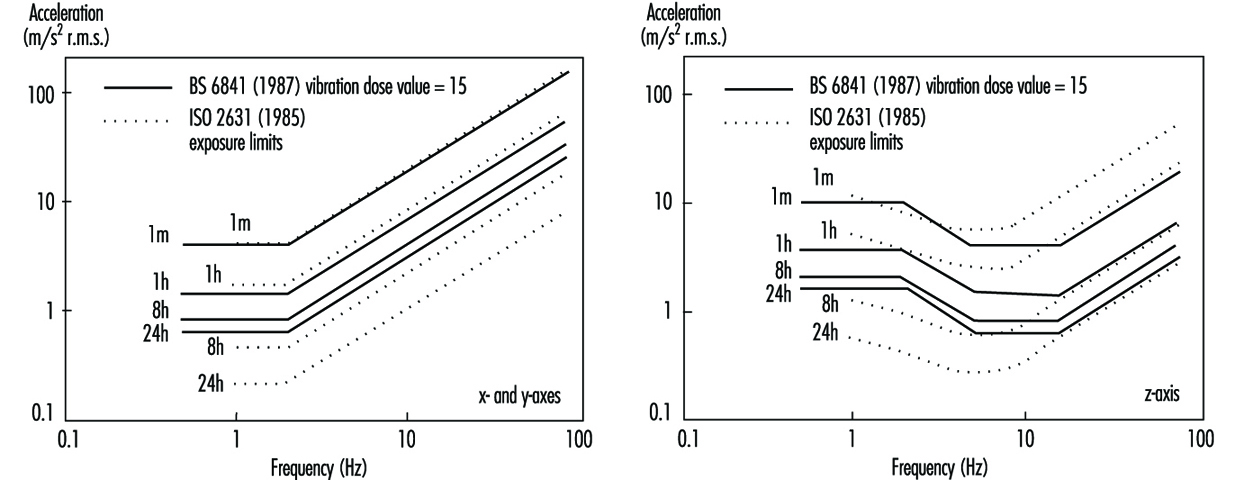
The vibration dose value can be considered to be the magnitude of a one-second duration of vibration which will be equally severe to the measured vibration. The vibration dose value uses a fourth-power time dependency to accumulate vibration severity over the exposure period from the shortest possible shock to a full day of vibration (e.g., BSI 6841):
Vibration dose value = 
The vibration dose value procedure can be used to evaluate the severity of both vibration and repetitive shocks. This fourth-power time dependency is simpler to use than the time dependency in ISO 2631 (see figure 2).
Figure 2. Time dependencies for human response to a whole-body vibration
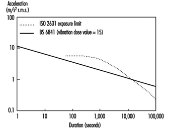
British Standard 6841 offers the following guidance.
High vibration dose values will cause severe discomfort, pain and injury. Vibration dose values also indicate, in a general way, the severity of the vibration exposures which caused them. However there is currently no consensus of opinion on the precise relation between vibration dose values and the risk of injury. It is known that vibration magnitudes and durations which produce vibration dose values in the region of 15 m/s1.75 will usually cause severe discomfort. It is reasonable to assume that increased exposure to vibration will be accompanied by increased risk of injury (BSI 1987b).
At high vibration dose values, prior consideration of the fitness of the exposed persons and the design of adequate safety precautions may be required. The need for regular checks on the health of routinely exposed persons may also be considered.
The vibration dose value provides a measure by which highly variable and complex exposures can be compared. Organizations may specify limits or action levels using the vibration dose value. For example, in some countries, a vibration dose value of 15 m/s1.75 has been used as a tentative action level, but it may be appropriate to limit vibration or repeated shock exposures to higher or lower values depending on the situation. With current understanding, an action level merely serves to indicate the approximate values that might be excessive. Figure 2 illustrates the root-mean-square accelerations corresponding to a vibration dose value of 15 m/s1.75 for exposures between one second and 24 hours. Any exposure to continuous vibration, intermittent vibration, or repeated shock may be compared with the action level by calculating the vibration dose value. It would be unwise to exceed an appropriate action level (or the exposure limit in ISO 2631) without consideration of the possible health effects of an exposure to vibration or shock.
The Machinery Safety Directive of the European Economic Community states that machinery must be designed and constructed so that hazards resulting from vibration produced by the machinery are reduced to the lowest practicable level, taking into account technical progress and the availability of means of reducing vibration. The Machinery Safety Directive (Council of the European Communities 1989) encourages the reduction of vibration by means additional to reduction at source (e.g., good seating).
Measurement and Evaluation of Exposure
Whole-body vibration should be measured at the interfaces between the body and the source of vibration. For seated persons this involves the placement of accelerometers on the seat surface beneath the ischial tuberosities of subjects. Vibration is also sometimes measured at the seat back (between the backrest and the back) and also at the feet and hands (see figure 3).
Figure 3. Axes for measuring vibration exposures of seated persons
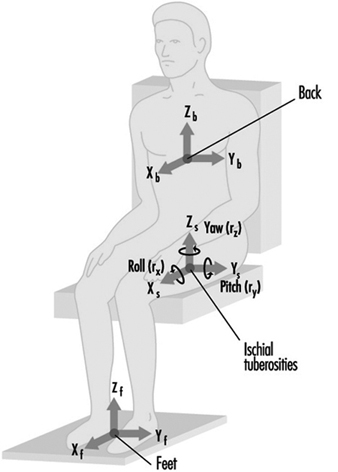
Epidemiological data alone are not sufficient to define how to evaluate whole-body vibration so as to predict the relative risks to health from the different types of vibration exposure. A consideration of epidemiological data in combination with an understanding of biodynamic responses and subjective responses is used to provide current guidance. The manner in which the health effects of oscillatory motions depend upon the frequency, direction and duration of motion is currently assumed to be the same as, or similar to, that for vibration discomfort. However, it is assumed that the total exposure, rather than the average exposure, is important, and so a dose measure is appropriate.
In addition to evaluating the measured vibration according to current standards, it is advisable to report the frequency spectra, magnitudes in different axes and other characteristics of the exposure, including the daily and lifetime exposure durations. The presence of other adverse environmental factors, especially sitting posture, should also be considered.
Prevention
Wherever possible, reduction of vibration at the source is to be preferred. This may involve reducing the undulations of the terrain or reducing the speed of travel of vehicles. Other methods of reducing the transmission of vibration to operators require an understanding of the characteristics of the vibration environment and the route for the transmission of vibration to the body. For example, the magnitude of vibration often varies with location: lower magnitudes will be experienced in some areas. Table 2 lists some preventive measures that may be considered.
Table 2. Summary of preventive measures to consider when persons are exposed to whole-body vibration
|
Group |
Action |
|
Management |
Seek technical advice |
|
|
Seek medical advice |
|
|
Warn exposed persons |
|
|
Train exposed persons |
|
|
Review exposure times |
|
|
Have policy on removal from exposure |
|
Machine manufacturers |
Measure vibration |
|
|
Design to minimize whole-body vibration |
|
|
Optimize suspension design |
|
|
Optimize seating dynamics |
|
|
Use ergonomic design to provide good posture etc. |
|
|
Provide guidance on machine maintenance |
|
|
Provide guidance on seat maintenance |
|
|
Provide warning of dangerous vibration |
|
Technical-at workplace |
Measure vibration exposure |
|
|
Provide appropriate machines |
|
|
Select seats with good attenuation |
|
|
Maintain machines |
|
|
Inform management |
|
Medical |
Pre-employment screening |
|
|
Routine medical checks |
|
|
Record all signs and reported symptoms |
|
|
Warn workers with apparent predisposition |
|
|
Advise on consequences of exposure |
|
|
Inform management |
|
Exposed persons |
Use machine properly |
|
|
Avoid unnecessary vibration exposure |
|
|
Check seat is properly adjusted |
|
|
Adopt good sitting posture |
|
|
Check condition of machine |
|
|
Inform supervisor of vibration problems |
|
|
Seek medical advice if symptoms appear |
|
|
Inform employer of relevant disorders |
Source: Adapted from Griffin 1990.
Seats can be designed to attenuate vibration. Most seats exhibit a resonance at low frequencies, which results in higher magnitudes of vertical vibration occurring on the seat than on the floor! At high frequencies there is usually attenuation of vibration. In use, the resonance frequencies of common seats are in the region of 4 Hz. The amplification at resonance is partially determined by the damping in the seat. An increase in the damping of the seat cushioning tends to reduce the amplification at resonance but increase the transmissibility at high frequencies. There are large variations in transmissibility between seats, and these result in significant differences in the vibration experienced by people.
A simple numerical indication of the isolation efficiency of a seat for a specific application is provided by the seat effective amplitude transmissibility (SEAT) (see Griffin 1990). A SEAT value greater than 100% indicates that, overall, the vibration on the seat is worse than the vibration on the floor. Values below 100% indicate that the seat has provided some useful attenuation. Seats should be designed to have the lowest SEAT value compatible with other constraints.
A separate suspension mechanism is provided beneath the seat pan in suspension seats. These seats, used in some off-road vehicles, trucks and coaches, have low resonance frequencies (around 2 Hz) and so can attenuate vibration at frequencies above about 3 Hz. The transmissibilities of these seats are usually determined by the seat manufacturer, but their isolation efficiencies vary with operating conditions.
Hand-Transmitted Vibration
Occupational Exposure
Mechanical vibration arising from powered processes or tools and entering the body at the fingers or the palm of the hands is called hand-transmitted vibration. Frequent synonyms for hand-transmitted vibration are hand-arm vibration and local or segmental vibration. Powered processes and tools which expose operators’ hands to vibration are widespread in several industrial activities. Occupational exposure to hand-transmitted vibration arises from hand-held powered tools used in manufacturing (e.g., percussive metal-working tools, grinders and other rotary tools, impact wrenches), quarrying, mining and construction (e.g., rock-drills, stone-hammers, pick-hammers, vibrocompactors), agriculture and forestry (e.g., chain saws, brush saws, barking machines) and public utilities (e.g., road and concrete breakers, drill-hammers, hand-held grinders). Exposure to hand-transmitted vibration can also occur from vibrating workpieces held in the hands of the operator as in pedestal grinding, and from hand-held vibrating controls as in operating lawn mowers or in controlling vibrating road compactors. It has been reported that the number of persons exposed to hand-transmitted vibration at work exceeds 150,000 in the Netherlands, 0.5 million in Great Britain, and 1.45 million in the United States. Excessive exposure to hand-transmitted vibration can cause disorders in the blood vessels, nerves, muscles, and bones and joints of the upper limbs. It has been estimated that 1.7 to 3.6% of the workers in European countries and the United States are exposed to potentially harmful hand-transmitted vibration (ISSA International Section for Research 1989). The term hand-arm vibration (HAV) syndrome is commonly used to refer to signs and symptoms associated with exposure to hand-transmitted vibration, which include:
- vascular disorders
- peripheral neurological disorders
- bone and joint disorders
- muscle disorders
- other disorders (whole body, central nervous system).
Leisure activities such as motorcycling or using domestic vibrating tools can occasionally expose the hands to vibration of high amplitude, but only long daily exposures may give rise to health problems (Griffin 1990).
The relationship between occupational exposure to hand-transmitted vibration and adverse health effects is far from simple. Table 1 lists some of the most important factors which concur to cause injuries in the upper limbs of vibration-exposed workers.
Table 1. Some factors potentially related to injurious effects during hand-transmitted vibration exposures
Vibration characteristics
- Magnitude (r.m.s., peak, weighted/unweighted)
- Frequency (spectra, dominant frequencies)
- Direction (x-, y-, z- axes)
Tools or processes
- Tool design (portable, fixed)
- Tool type (percussive, rotary, rotating percussive)
- Condition
- Operation
- Material being worked
Exposure conditions
- Duration (daily, yearly exposures)
- Pattern of exposure (continuous, intermittent, rest periods)
- Cumulative exposure duration
Environmental conditions
- Ambient temperature
- Airflow
- Humidity
- Noise
- Dynamic response of the finger-hand-arm system
- Mechanical impedance
- Vibration transmissibility
- Absorbed energy
Individual characteristics
- Method of working (grip force, push force, hand-arm posture, body position)
- Health
- Training
- Skill
- Use of gloves
- Individual susceptibility to injury
Biodynamics
It may be presumed that factors influencing the transmission of vibration into the finger-hand-arm system play a relevant role in the genesis of vibration injury. The transmission of vibration depends on both the physical characteristics of vibration (magnitude, frequency, direction) and the dynamic response of the hand (Griffin 1990).
Transmissibility and impedance
Experimental results indicate that the mechanical behaviour of the human upper limb is complex, as the impedance of the hand-arm system—that is, its resistance to vibrate—shows pronounced variations with the change in vibration amplitude, frequency and direction, applied forces, and orientation of the hand and arm with respect to the axis of the stimulus. Impedance is also influenced by body constitution and structural differences of the various parts of the upper limb (e.g., the mechanical impedance of the fingers is much lower than that of the palm of the hand). In general, higher vibration levels, as well as tighter hand-grips, result in greater impedance. However, the change in impedance has been found to be highly dependent on the frequency and direction of the vibration stimulus and various sources of both intra- and inter-subject variability. A resonance region for the finger-hand-arm system in the frequency range between 80 and 300 Hz has been reported in several studies.
Measurements of the transmission of vibration through the human arm have shown that lower frequency vibration (>50 Hz) is transmitted with little attenuation along the hand and forearm. The attenuation at the elbow is dependent on the arm posture, as the transmission of vibration tends to decrease with the increase of the flexion angle at the elbow joint. For higher frequencies (>50 Hz), the transmission of vibration progressively decreases with increasing frequency, and above 150 to 200 Hz most of the vibrational energy is dissipated in the tissues of the hand and fingers. From transmissibility measurements it has been inferred that in the high-frequency region vibration may be responsible for damage to the soft structures of the fingers and hands, while low-frequency vibration of high amplitude (e.g., from percussive tools) might be associated with injuries to the wrist, elbow and shoulder.
Factors influencing finger and hand dynamics
The adverse effects from vibration exposure may be assumed to be related to the energy dissipated in the upper limbs. Energy absorption is highly dependent on factors affecting the coupling of the finger-hand system to the vibration source. Variations in grip pressure, static force and posture modify the dynamic response of the finger, hand and arm, and, consequently, the amount of energy transmitted and absorbed. For instance, grip pressure has a considerable influence on energy absorption and, in general, the higher the hand grip the greater the force transmitted to the hand-arm system. Dynamic response data can provide relevant information to assess the injury potential of tool vibration and to assist in the development of anti-vibration devices such as hand-grips and gloves.
Acute Effects
Subjective discomfort
Vibration is sensed by various skin mechanoreceptors, which are located in the (epi)dermal and subcutaneous tissues of the smooth and bare (glabrous) skin of the fingers and hands. They are classified into two categories—slow and fast adapting—according to their adaptation and receptive field properties. Merkel discs and Ruffini endings are found in the slow-adapting mechanoreceptive units, which respond to static pressure and slow changes in pressure and are excited at low frequency (<16 Hz). Fast-adapting units have Meissner’s corpuscles and Pacinian corpuscles, which respond to rapid changes in stimulus and are responsible for vibratory sensation in the frequency range between 8 and 400 Hz. The subjective response to hand-transmitted vibration has been used in several studies to obtain threshold values, contours of equivalent sensation and unpleasant or tolerance limits for vibratory stimuli at different frequencies (Griffin 1990). Experimental results indicate that human sensitivity to vibration decreases with increasing frequency for both comfort and annoyance vibration levels. Vertical vibration appears to cause more discomfort than vibration in other directions. Subjective discomfort has also been found to be a function of the spectral composition of vibration and the grip force exerted on the vibrating handle.
Activity interference
Acute exposure to hand-transmitted vibration can cause a temporary increase in vibrotactile thresholds due to a depression of the excitability of the skin mechanoreceptors. The magnitude of the temporary threshold shift as well as the time for recovery is influenced by several variables, such as the characteristics of the stimulus (frequency, amplitude, duration), temperature as well as the worker’s age and previous exposure to vibration. Exposure to cold aggravates the tactile depression induced by vibration, because low temperature has a vasoconstrictive effect on digital circulation and reduces finger skin temperature. In vibration-exposed workers who often operate in a cold environment, repeated episodes of acute impairment of tactile sensitivity can lead to permanent reduction in sensory perception and loss of manipulative dexterity, which, in turn, can interfere with work activity, increasing the risk for acute injuries due to accidents.
Non-Vascular Effects
Skeletal
Vibration-induced bone and joint injuries are a controversial matter. Various authors consider that disorders of bones and joints in workers using hand-held vibrating tools are not specific in character and similar to those due to the ageing process and to heavy manual work. On the other hand, some investigators have reported that characteristic skeletal changes in the hands, the wrists and the elbows can result from prolonged exposure to hand-transmitted vibration. Early x-ray investigations had revealed a high prevalence of bone vacuoles and cysts in the hands and wrists of vibration-exposed workers, but more recent studies have shown no significant increase with respect to control groups made up of manual workers. Excess prevalence of wrist osteoarthrosis and elbow arthrosis and osteophytosis has been reported in coal miners, road construction workers and metal-working operators exposed to shocks and low frequency vibration of high amplitude from pneumatic percussive tools. On the contrary, there is little evidence for an increased prevalence of degenerative bone and joint disorders in the upper limbs of workers exposed to mid- or high-frequency vibrations arising from chain saws or grinding machines. Heavy physical effort, forceful gripping and other biomechanical factors can account for the higher occurrence of skeletal injuries found in workers operating percussive tools. Local pain, swelling, and joint stiffness and deformities may be associated with radiological findings of bone and joint degeneration. In a few countries (including France, Germany, Italy), bone and joint disorders occurring in workers using hand-held vibrating tools are considered to be an occupational disease, and the affected workers are compensated.
Neurological
Workers handling vibrating tools may experience tingling and numbness in their fingers and hands. If vibration exposure continues, these symptoms tend to worsen and can interfere with work capacity and life activities. Vibration-exposed workers may exhibit increased vibratory, thermal and tactile thresholds in clinical examinations. It has been suggested that continuous vibration exposure can not only depress the excitability of skin receptors but also induce pathological changes in the digital nerves such as perineural oedema, followed by fibrosis and nerve fibre loss. Epidemiological surveys of vibration-exposed workers show that the prevalence of peripheral neurological disorders varies from a few per cent to more than 80 per cent, and that sensory loss affects users of a wide range of tool types. It seems that vibration neuropathy develops independently of other vibration-induced disorders. A scale of the neurological component of the HAV syndrome was proposed at the Stockholm Workshop 86 (1987), consisting of three stages according to the symptoms and the results of clinical examination and objective tests (table 2).
Table 2. Sensorineural stages of the Stockholm Workshop scale for the hand-arm vibration syndrome
|
Stage |
Signs and symptoms |
|
0SN |
Exposed to vibration but no symptoms |
|
1SN |
Intermittent numbness, with or without tingling |
|
2SN |
Intermittent or persistent numbness, reduced sensory perception |
|
3SN |
Intermittent or persistent numbness, reduced tactile discrimination and/or |
Source: Stockholm Workshop 86 1987.
Careful differential diagnosis is required to distinguish vibration neuropathy from entrapment neuropathies, such as carpal tunnel syndrome (CTS), a disorder due to compression of the median nerve as it passes through an anatomical tunnel in the wrist. CTS seems to be a common disorder in some occupational groups using vibrating tools, such as rock-drillers, platers and forestry workers. It is believed that ergonomic stressors acting on the hand and wrist (repetitive movements, forceful gripping, awkward postures), in addition to vibration, can cause CTS in workers handling vibrating tools. Electroneuromyography measuring sensory and motor nerve velocities has proven to be useful to differentiate CTS from other neurological disorders.
Muscular
Vibration-exposed workers may complain of muscle weakness and pain in the hands and arms. In some individuals muscle fatigue can cause disability. A decrease in hand-grip strength has been reported in follow-up studies of lumberjacks. Direct mechanical injury or peripheral nerve damage have been suggested as possible aetiological factors for muscle symptoms. Other work-related disorders have been reported in vibration-exposed workers, such as tendinitis and tenosynovitis in the upper limbs, and Dupuytren’s contracture, a disease of the fascial tissue of the palm of the hand. These disorders seem to be related to ergonomic stress factors arising from heavy manual work, and the association with hand-transmitted vibration is not conclusive.
Vascular Disorders
Raynaud’s phenomenon
Giovanni Loriga, an Italian physician, first reported in 1911 that stone cutters using pneumatic hammers on marble and stone blocks at some yards in Rome suffered from finger blanching attacks, resembling the digital vasospastic response to cold or emotional stress described by Maurice Raynaud in 1862. Similar observations were made by Alice Hamilton (1918) among stone cutters in the United States, and later by several other investigators. In the literature various synonyms have been used to describe vibration-induced vascular disorders: dead or white finger, Raynaud’s phenomenon of occupational origin, traumatic vasospastic disease, and, more recently, vibration-induced white finger (VWF). Clinically, VWF is characterized by episodes of white or pale fingers caused by spastic closure of the digital arteries. The attacks are usually triggered by cold and last from 5 to 30 to 40 minutes. A complete loss of tactile sensitivity may be experienced during an attack. In the recovery phase, commonly accelerated by warmth or local massage, redness may appear in the affected fingers as a result of a reactive increase of blood flow in the cutaneous vessels. In the rare advanced cases, repeated and severe digital vasospastic attacks can lead to trophic changes (ulceration or gangrene) in the skin of the fingertips. To explain cold-induced Raynaud’s phenomenon in vibration-exposed workers, some researchers invoke an exaggerated central sympathetic vasoconstrictor reflex caused by prolonged exposure to harmful vibration, while others tend to emphasize the role of vibration-induced local changes in the digital vessels (e.g., thickening of the muscular wall, endothelial damage, functional receptor changes). A grading scale for the classification of VWF has been proposed at the Stockholm Workshop 86 (1987), (table 3). A numerical system for VWF symptoms developed by Griffin and based on scores for the blanching of different phalanges is also available (Griffin 1990). Several laboratory tests are used to diagnose VWF objectively. Most of these tests are based on cold provocation and the measurement of finger skin temperature or digital blood flow and pressure before and after cooling of fingers and hands.
Table 3. The Stockholm Workshop scale for staging cold-induced Raynaud’s phenomenon in the hand-arm vibration syndrome
|
Stage |
Grade |
Symptoms |
|
0 |
— |
No attacks |
|
1 |
Mild |
Occasional attacks affecting only the tips of one or more fingers |
|
2 |
Moderate |
Occasional attacks affecting distal and middle (rarely also |
|
3 |
Severe |
Frequent attacks affecting all phalanges of most fingers |
|
4 |
Very severe |
As in stage 3, with trophic skin changes in the finger tips |
Source: Stockholm Workshop 86 1987.
Epidemiological studies have pointed out that the prevalence of VWF is very wide, from less than 1 to 100 per cent. VWF has been found to be associated with the use of percussive metal-working tools, grinders and other rotary tools, percussive hammers and drills used in excavation, vibrating machinery used in the forest, and other powered tools and processes. VWF is recognized as an occupational disease in many countries. Since 1975–80 a decrease in the incidence of new cases of VWF has been reported among forestry workers in both Europe and Japan after the introduction of anti-vibration chain saws and administrative measures curtailing saw usage time. Similar findings are not yet available for tools of other types.
Other Disorders
Some studies indicate that in workers affected with VWF hearing loss is greater than that expected on the basis of ageing and noise exposure from the use of vibrating tools. It has been suggested that VWF subjects may have an additional risk of hearing impairment due to vibration-induced reflex sympathetic vasoconstriction of the blood vessels supplying the inner ear. In addition to peripheral disorders, other adverse health effects involving the endocrine and central nervous system of vibration-exposed workers have been reported by some Russian and Japanese schools of occupational medicine (Griffin 1990). The clinical picture, called “vibration disease,” includes signs and symptoms related to dysfunction of the autonomic centres of the brain (e.g., persistent fatigue, headache, irritability, sleep disturbances, impotence, electroencephalographic abnormalities). These findings should be interpreted with caution and further carefully designed epidemiological and clinical research work is needed to confirm the hypothesis of an association between disorders of the central nervous system and exposure to hand-transmitted vibration.
Standards
Several countries have adopted standards or guidelines for hand-transmitted vibration exposure. Most of them are based on the International Standard 5349 (ISO 1986). To measure hand-transmitted vibration ISO 5349 recommends the use of a frequency-weighting curve which approximates the frequency-dependent sensitivity of the hand to vibration stimuli. The frequency-weighted acceleration of vibration (ah,w) is obtained with an appropriate weighting-filter or by summation of weighted acceleration values measured in octave or one-third octave bands along an orthogonal coordinate system (xh, yh, zh), (figure 1). In ISO 5349 the daily exposure to vibration is expressed in terms of energy-equivalent frequency-weighted acceleration for a period of four hours ((ah,w)eq(4) in m/s2 r.m.s), according to the following equation:
(ah,w)eq(4)=(T/4)½(ah,w)eq(T)
where T is the daily exposure time expressed in hours and (ah,w)eq(T) is the energy-equivalent frequency-weighted acceleration for the daily exposure time T. The standard provides guidance to calculate (ah,w)eq(T) if a typical work-day is characterized by several exposures of different magnitudes and durations. Annex A to ISO 5349 (which does not form part of the standard) proposes a dose-effect relationship between (ah,w)eq(4) and VWF, which can be approximated by the equation:
C=[(ah,w)eq(4) TF/95]2 x 100
where C is the percentile of exposed workers expected to show VWF (in the range 10 to 50%), and TF is the exposure time before finger blanching among the affected workers (in the range 1 to 25 years). The dominant, single-axis component of vibration directed into the hand is used to calculate (ah,w)eq(4), which should not be in excess of 50 m/s2. According to the ISO dose-effect relationship, VWF may be expected to occur in about 10% of workers with daily vibration exposure to 3 m/s2 for ten years.
Figure 1. Basicentric coordinate system for the measurement of hand-transmitted vibration
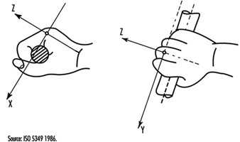
In order to minimize the risk of vibration-induced adverse health effects, action levels and threshold limit values (TLVs) for vibration exposure have been proposed by other committees or organizations. The American Conference of Government Industrial Hygienists (ACGIH) has published TLVs for hand-transmitted vibration measured according to the ISO frequency-weighting procedure (American Conference of Governmental Industrial Hygienists 1992), (table 4). According to ACGIH, the proposal TLVs concern vibration exposure to which “nearly all workers may be exposed repeatedly without progressing beyond Stage 1 of the Stockholm Workshop Classification System for VWF”. More recently, exposure levels for hand-transmitted vibration have been presented by the Commission of the European Communities within a proposal of a Directive for the protection of workers against the risks arising from physical agents (Council of the European Union 1994), (table 5). In the proposed Directive the quantity used for the assessment of vibration hazard is expressed in terms of an eight-hour energy-equivalent frequency-weighted acceleration, A(8)=(T/8)½ (ah,w)eq(T), by using the vector sum of weighted accelerations determined in orthogonal coordinates asum=(ax,h,w2+ay,h,w2+az,h,w2)½ on the vibrating tool handle or workpiece. The methods of measurement and assessment of vibration exposure reported in the Directive are basically derived from the British Standard (BS) 6842 (BSI 1987a). The BS standard, however, does not recommend exposure limits, but provides an informative appendix on the state of knowledge of the dose-effect relationship for hand-transmitted vibration. The estimated frequency-weighted acceleration magnitudes liable to cause VWF in 10% of workers exposed to vibration according to the BS standard are reported in table 6.
___________________________________________________________________________
Table 4. Threshold limit values for hand-transmitted vibration
|
Total daily exposure (hours) |
Frequency-weighted r.m.s. acceleration in the dominant direction that should not be exceeded |
|
|
|
|
g* |
|
4-8 |
4 |
0.40 |
|
2-4 |
6 |
0.61 |
|
1-2 |
8 |
0.81 |
|
1 |
12 |
1.22 |
* 1 g = 9.81 ![]() .
.
Source: According to the American Conference of Government Industrial Hygienists 1992.
___________________________________________________________________________
Table 5. Proposal of the Council of the European Union for a Council Directive on physical agents: Annex II A. Hand-transmitted vibration (1994)
|
Levels ( |
A(8)* |
Definitions |
|
Threshold |
1 |
The exposure value below which continuous and/or repetitive exposure has no adverse effect on health and safety of workers |
|
Action |
2.5 |
The value above which one or more of the measures** specified in the relevant Annexes must be undertaken |
|
Exposure limit value |
5 |
The exposure value above which an unprotected person is exposed to unacceptable risks. Exceeding this level is prohibited and must be prevented through the implementation of the provisions of the Directive*** |
* A(8) = 8 h energy-equivalent frequency-weighted acceleration.
** Information, training, technical measures, health surveillance.
*** Appropriate measures for the protection of health and safety.
___________________________________________________________________________
Table 6. Frequency-weighted vibration acceleration magnitudes (![]() r.m.s.) which may be expected to produce finger blanching in 10% of persons exposed*
r.m.s.) which may be expected to produce finger blanching in 10% of persons exposed*
|
Daily exposure (hours) |
Life-time exposure (years) |
|||||
|
|
0.5 |
1 |
2 |
4 |
8 |
16 |
|
0.25 |
256.0 |
128.0 |
64.0 |
32.0 |
16.0 |
8.0 |
|
0.5 |
179.2 |
89.6 |
44.8 |
22.4 |
11.2 |
5.6 |
|
1 |
128.0 |
64.0 |
32.0 |
16.0 |
8.0 |
4.0 |
|
2 |
89.6 |
44.8 |
22.4 |
11.2 |
5.6 |
2.8 |
|
4 |
64.0 |
32.0 |
16.0 |
8.0 |
4.0 |
2.0 |
|
8 |
44.8 |
22.4 |
11.2 |
5.6 |
2.8 |
1.4 |
* With short duration exposure the magnitudes are high and vascular disorders may not be the first adverse symptom to develop.
Source: According to British Standard 6842. 1987, BSI 1987a.
___________________________________________________________________________
Measurement and Evaluation of Exposure
Vibration measurements are made to provide assistance for the development of new tools, to check vibration of tools at purchase, to verify maintenance conditions, and to assess human exposure to vibration at the workplace. Vibration-measuring equipment generally consists of a transducer (usually an accelerometer), an amplifying device, filter (bandpass filter and/or frequency-weighting network), and amplitude or level indicator or recorder. Vibration measurements should be made on the tool handle or workpiece close to the surface of the hand(s) where the vibration enters the body. Careful selection of the accelerometers (e.g., type, mass, sensitivity) and appropriate methods of mounting the accelerometer on the vibrating surface are required to obtain accurate results. Vibration transmitted to the hand should be measured and reported in the appropriate directions of an orthogonal coordinate system (figure 1). The measurement should be made over a frequency range of at least 5 to 1,500 Hz, and the acceleration frequency content of vibration in one or more axes can be presented in octave bands with centre frequencies from 8 to 1,000 Hz or in one-third octave bands with centre frequencies from 6.3 to 1,250 Hz. Acceleration can also be expressed as frequency-weighted acceleration by using a weighting network which complies with the characteristics specified in ISO 5349 or BS 6842. Measurements at the workplace show that different vibration magnitudes and frequency spectra can occur on tools of the same type or when the same tool is operated in a different manner. Figure 2 reports the mean value and the range of distribution of weighted accelerations measured in the dominant axis of power-driven tools used in forestry and industry (ISSA International Section for Research 1989). In several standards hand-transmitted vibration exposure is assessed in terms of four-hour or eight-hour energy-equivalent frequency-weighted acceleration calculated by means of the equations above. The method for obtaining energy-equivalent acceleration assumes that the daily exposure time required to produce adverse health effects is inversely proportional to the square of frequency-weighted acceleration (e.g., if the vibration magnitude is halved then exposure time may be increased by a factor of four). This time dependency is considered to be reasonable for standardization purposes and is convenient for instrumentation, but it should be noted that it is not fully substantiated by epidemiological data (Griffin 1990).
Figure 2. Mean values and range of distribution of frequency-weighted r.m.s. acceleration in the dominant axis measured on the handle(s) of some power tools used in forestry and industry
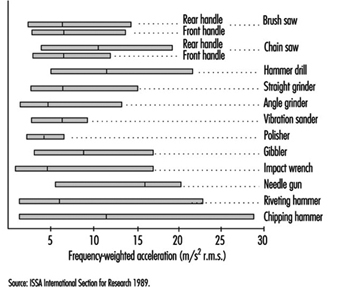
Prevention
The prevention of injuries or disorders caused by hand-transmitted vibration requires the implementation of administrative, technical and medical procedures (ISO 1986; BSI 1987a). Appropriate advice to the manufacturers and users of vibrating tools should also be given. Administrative measures should include adequate information and training to instruct the operators of vibrating machinery to adopt safe and correct work practices. Since continuous exposure to vibration is believed to increase vibration hazard, work schedules should be arranged to include rest periods. Technical measures should include the choice of tools with the lowest vibration and with appropriate ergonomic design. According to the EC Directive for the safety of machinery (Council of the European Communities 1989), the manufacturer shall make public whether the frequency-weighted acceleration of hand-transmitted vibration exceeds 2.5 m/s2, as determined by suitable test codes such as indicated in the International Standard ISO 8662/1 and its companion documents for specific tools (ISO 1988). Tool maintenance conditions should be carefully checked by periodic vibration measurements. Pre-employment medical screening and subsequent clinical examinations at regular intervals should be performed on vibration-exposed workers. The aims of medical surveillance are to inform the worker of the potential risk associated with vibration exposure, to assess health status and to diagnose vibration-induced disorders at the early stage. At the first screening examination particular attention should be paid to any condition which may be aggravated by exposure to vibration (e.g., constitutional tendency to white finger, some forms of secondary Raynaud’s phenomenon, past injuries to the upper limbs, neurological disorders). Avoidance or reduction of vibration exposure for the affected worker should be decided after considering both the severity of symptoms and the characteristics of the entire working process. The worker should be advised to wear adequate clothing to keep the entire body warm, and to avoid or minimize the smoking of tobacco and the use of some drugs which can affect peripheral circulation. Gloves may be useful to protect the fingers and hands from traumas and to keep them warm. So-called anti-vibration gloves may provide some isolation of the high frequency components of vibration arising from some tools.
" DISCLAIMER: The ILO does not take responsibility for content presented on this web portal that is presented in any language other than English, which is the language used for the initial production and peer-review of original content. Certain statistics have not been updated since the production of the 4th edition of the Encyclopaedia (1998)."